Good to know that I am not the only one to experience trouble with the chinese ESCs.
As for your questions, Lee:
First of all, the connections as you described them sound correct. I use a similar setup with the ESC plugged into the throttle channel of the receiver, the steering servo on the steering channel.
One more servo is plugged into one of the toggle switch channels for the two speed gearbox and the LEDs get their power from a spare channel.
When connecting LEDs to a power source it is best practice to add a resistor in the circuit. The resistor rating can be computed as: R = U / I where
U is the desired voltage drop at the resistor
I is the amperage of the LED(s)
R is the resulting resistor rating
The voltage drop U is best described with an example:
A normal white LED needs approx. 3.3V, the voltage supplied by the BEC in the ESC is around 6V. To prevent the LED from dying you need a voltage drop of (6 - 3.3)V = 2.7V
The typical amperage of a white LED is 20mA or 0.02A
When these values are set in the equation you get 2.7V / 0.02A = 135 Ohm
As this rating is not available just take the closest one which is 150 Ohm. This is what I use and it works perfectly well so far. The downside is that you actually need one resistor for each white LED.
Just connecting two LEDs which are connected in series directly to the power source may actually overload the power source as the LEDs need 2 * 3.3V = 6.6V which exceeds the available 6V.
I am not an electrical genius and therefore cannot tell you what might cause your problem but it sounds to me as if the receiver continuously loses power thus causing the flicker of the LEDs and the strange servo behavior. The second ESC you tested might output a little more power and therefore run more stable.
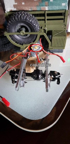
In your case I would try to connect the LEDs parallel with one 150 Ohm resistor each. If this does not fix the problem, you might suffer of radio interference caused by the motor. In this case you need to add some capacitors to the motor circuit. Start by adding one 100nF capacitor parallel to the motor (i.e. between positive and negative contact of the motor). BE SURE TO USE CERAMIC CAPACITORS! Other types will blow up when the polarity changes when you switch from forward to reverse!
If this still doesn't help, add two 47nF capacitors, one to each motor connector. The second pin of those two capacitors is soldered to the motor.

- Capacitors to eliminate radio interference
I hope that I did not completely confuse you.
Have fun, regards,
Reinhard
