I tried the STL import thing in Openscad. It doesn't give you an editable file, it simply imports the whole thing with one command. What I had to do was use it as a template to build the part that I wanted around it, eg holes in the correct place and correct diameter. Then comment out the import code so that i was left with the part that I designed. In this example I imported two of the printer parts, aligned them, and then designed a new part that was one piece.
Printer part 1:
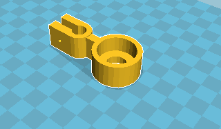
- Screenshot from 2017-01-31 09-09-42.png (8.01 KiB) Viewed 843 times
Printer part 2
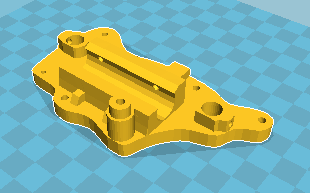
- Screenshot from 2017-01-31 09-10-12.png (11.34 KiB) Viewed 843 times
New part above:
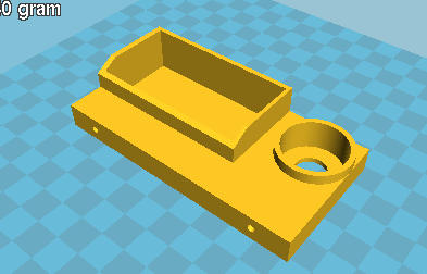
- Screenshot from 2017-01-31 09-08-55.png (11.54 KiB) Viewed 843 times
New part underneath:
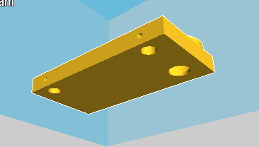
- under.png (3.95 KiB) Viewed 843 times
Printed new part:
The way to do it is :
//module antiwobble()
//{
//import("/home/rob/Desktop/Smartrap Parts/RELEASE/antiwobble_support 8mm.stl");
//}
//
//module base()
//{
//import("/home/rob/Desktop/Smartrap Parts/RELEASE/plate_base.stl");
//}
module topsteady()
{
$fn=100;
difference()
{
union()
{
translate([-45,-66,17])cylinder(14,14,14);//bearing outer case
translate([-59,-80,17])cube([100,50,10]);//base plate
translate([-26,-80,23])cube([67,35,15]);//tools
}
translate([28,-37.5,4])cylinder(20,4.1,4.1);//rod hole
translate([-45,-37.5,4])cylinder(20,4.1,4.1);//rod hole
translate([-45,-66,0])cylinder(50,6,6);//thread hole
translate([-45,-66,19])cylinder(14.1,12,12);//bearing inner
translate([-24.5,-78,24])cube([63,31,15]);//tools
translate([-30,-77,52])rotate([-30,0,0])cube([75,37,15]);//tools slope sides
translate([28,-26,22])rotate([90,0,0])cylinder(10,1.5,1.5);//clamp screw hole;
translate([-45,-26,22])rotate([90,0,0])cylinder(10,1.5,1.5);//clamp screw hole;
translate([-9,-62.5,20])rotate([0,0,0])cylinder(20,16,16);//pritt stick
}
}
topsteady();