1 Kompanie PzAbt 101 Tiger 131 Walter Hahn Project Diary

User avatar
Wildboar44
Corporal
Posts: 392
Joined: Sun Jan 13, 2013 10:28 pm
Location: Kent England UK.

Re: 1 Kompanie PzAbt 101 Tiger 131 Walther Hahn Project Dia

Post by Wildboar44 »

By chance , after several blurry eye'd googling sessions , I may have come up with a solution to scale chain !

After link to link to god knows where I came across this, it is called " Fusee chain " and is used in early turn of the century pocket watches and small clocks .

Emails have been sent out to several period antique watch repair specialists ........ I can just image the conversation !

Now who wants a guess on what that will cost per inch ....... bet it rimes with Ouch ! :lolno:
Last edited by Wildboar44 on Sun Dec 01, 2019 11:03 am, edited 2 times in total.
Yesterday is our history, Tomorrow is an eternal mistery, Today is a gift, its why its called "The Present".
jonger
Lance Corporal
Posts: 215
Joined: Tue Jan 04, 2011 8:39 pm
Location: Charnwood Leicestershire

Re: 1 Kompanie PzAbt 101 Tiger 131 Walther Hahn Project Dia

Post by jonger »

Wildboar44 wrote:By chance , after several blurry eye'd googling sessions , I may have come up with a solution to scale chain !

After link to link to god knows where I came across this , it is called " Fusee chain " and is used in early turn of the
century pocket watches and small clocks .
Wildboar44
One of my other hobbies is pocket watch repairing and I can tell you fusee chain is well sought after as fusee watches are what collectors go for, especially verge fusee pocket watches - some prime examples go for thousands of pounds, so original fusee chain is not cheap - good luck with your quest
Oh and if you do find a source of cheap fusee chain let me know - I need some to repair a watch or two :D
Jonger
User avatar
Wildboar44
Corporal
Posts: 392
Joined: Sun Jan 13, 2013 10:28 pm
Location: Kent England UK.

Re: 1 Kompanie PzAbt 101 Tiger 131 Walther Hahn Project Dia

Post by Wildboar44 »

jonger wrote:
Wildboar44 wrote:By chance , after several blurry eye'd googling sessions , I may have come up with a solution to scale chain !

After link to link to god knows where I came across this , it is called " Fusee chain " and is used in early turn of the
century pocket watches and small clocks .
Wildboar44
One of my other hobbies is pocket watch repairing and I can tell you fusee chain is well sought after as fusee watches are what collectors go for, especially verge fusee pocket watches - some prime examples go for thousands of pounds, so original fusee chain is not cheap - good luck with your quest
Oh and if you do find a source of cheap fusee chain let me know - I need some to repair a watch or two :D

Hey jonger .... just found this comapany , they seem to list a few sizes too 8)

http://www.obsoletewatchandclockparts.c ... Chains.htm


.
Yesterday is our history, Tomorrow is an eternal mistery, Today is a gift, its why its called "The Present".
User avatar
Wildboar44
Corporal
Posts: 392
Joined: Sun Jan 13, 2013 10:28 pm
Location: Kent England UK.

Re: 1 Kompanie PzAbt 101 Tiger 131 Walther Hahn Project Dia

Post by Wildboar44 »

Eastern Front wrote:You know, impact or somebody like that makes the chain for the travel lock out of PE, I know if you look on Wecohe's website you will see it..
instead of using all the links you could just use what you need...

Cheers!

Hey Eastern ,

I am only just getting to grips with using plasticard and making alterations , building PE brass still scares me !.Plus there is the cost of the clamps and tiny pliers / magnifying lenses ....

Plus with my dress sense and thick glasses.... Can you see me doing PE Parts ?
Last edited by Wildboar44 on Sun Dec 01, 2019 11:04 am, edited 2 times in total.
Yesterday is our history, Tomorrow is an eternal mistery, Today is a gift, its why its called "The Present".
User avatar
maxmekker
Warrant Officer 1st Class
Posts: 1718
Joined: Tue Apr 27, 2010 8:47 am
Location: Norway

Re: 1 Kompanie PzAbt 101 Tiger 131 Walther Hahn Project Dia

Post by maxmekker »

my gosh that's some fine work mister.
Drammen Rock City
User avatar
Wildboar44
Corporal
Posts: 392
Joined: Sun Jan 13, 2013 10:28 pm
Location: Kent England UK.

Re: 1 Kompanie PzAbt 101 Tiger 131 Walther Hahn Project Dia

Post by Wildboar44 »

Updated 24-11-2019

Once again, just a reminder that this HL Tiger dates back to 2013 and so this Turret correction may not be required on later models produced by HL.

The Heng long Tiger 1 Turret " Correction"


Part 1 . The Turret Base

This update goes through correcting the Turret on the HL Tiger 1, I was not going to do this modification at the start of the build as there were very few detailed "how to's" on the method's employed although there are many finished examples. So for a long time i put the idea out of my head and got on with the list of build jobs.

I was only going to move the Turret vent and add a loaders periscope. However ,after taking inspiration from Tanks-for-the-Memory's detailed information on incorrect Turret bins and deciding to cut the HL bin off and install the correct Tamiya bin, I thought well in for a penny, in for a pound I may as well make sure it is the correct place !

1 -Using masking tape on the Hull, mark the position of the Turret Bin in Standard Form
2 -Now repeat with the Turret turned 90 Degree AND flush with Hull Sides.
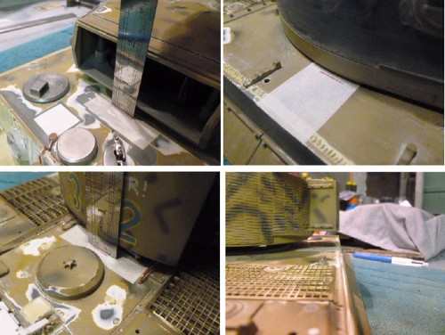
Taking location measurents (Click for larger image )
N:BMake sure you take all these measurements of the STD location with the Turret ring drive gear screwed in place. This ensures the most accurate measurements or you will have some slack.

Line 1 is the position of the front of the Turret with the bin Flush with the Hull in its "correct" position .
Line 2 is the reference mark for side of Turret facing forward.
Line 3 is the position of the front of the Turret with the original bin hanging over the side.
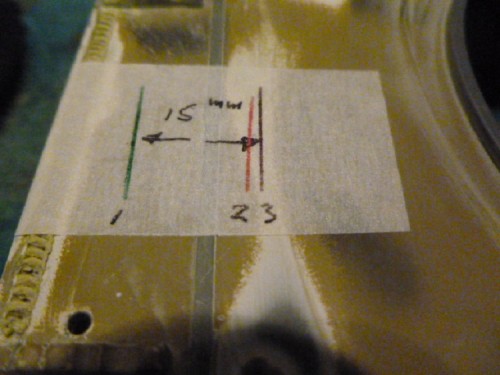
Difference between correct and incorrect position front turret when turned 90 degree
As you can see the difference is 15mm , I have seen 13.5 and 14.5mm mentioned before on some posts, but I settled on 15mm as it looked correct. NOTE : 2019 Update. 13.5mm is more accurate. See Hull correction.


3 -Screw a timber slat inside the Turret Base, this is 19x75mm on section
4 -Use posts circled to line up centre of the circle A, mark on tape the centre and 15mm "backset" B to rear
5 -Using a Jakar compass cutter placed in the centre point A, you score 3/4 through thickness (NOT FULLY)
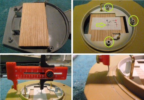
Scoring out the Centre A ring ( Click for larger image )
Just make sure you take your time, firm pressure but not hard, cutting even sections at a time working around the circle a 1/4 circle at a time. Regular checks underneath until you see a very faint line in the under side and STOP Thanks to Tanks-for-the-Memory for this method.

6 -Stop when you see this mark coming through.
7 -Now switch to Point B and working in the same method work on this crescent cut out until fully removed alternating with Point A.
8 -As you can see it removes with a nice clean edge.
Point B offset cutting and removal (Click for larger image )
9 -Working back on Point A, score under these BB/Recoil mounting posts until fully through.
10-With a razor saw, cut under the ribs flush to disconnect them from your workings
11-Complete the full removal of centre section.
12-BB/Recoil mounts are left intact
Completing the Circle A and under sawing BB/Recoil Mounts. (Click for larger images )
13-Crescent Section B is now moved to the rear
14-A few styrene tabs temporarily hold things in place.
15-You can see the original post mounts and how much the Turret have moved forward (Yes forward!)
16-With the Turret rotation gear back in place check it is now flush
Swopping over Section A and B and checking allignment. ( Click for larger image )
17-Bond in sections of 0.25mm styrene to replace material under BB/Recoil mounting posts lost in sawing through.
18-Additional side tabs.
19-Main front and rear supports tabs 1.5mm styrene.
20-Turret main opening is now 15mm more toward the rear.
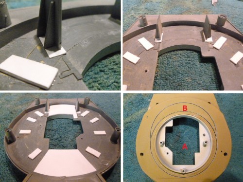
Reinforcing from inside and completed swop of removed sections ( Click for larger image )
21-0.5mm Styrene plate added underneath
21-Ensure this extends flush with the outside profile of Turret Base. At this stage I removed the HL Bin base as I will be adding a Tamiya replacement which is the correct size and shape.
22-This is the Undercut / recess void to be filled with milliput.
23-Completed
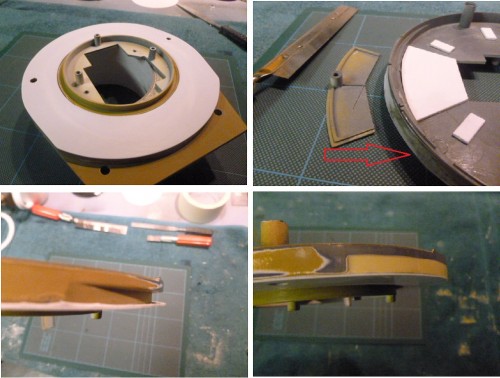
Larger 0.50mm styrene plate bonded to reinforce bottom and used as template to fill undercut ( Click for larger image )
However, once back in place there is more work to do as the Turret whilst flush with the Hull when turned 90 degree it is now too far forward when the Turret faces front
This is how far forward the whole Turret is moved forward without Part 2 correcting the Hull
Turret Bin now correctly flush with Hull, but main Turret is too far forward. (Click for larger image )


.
Thanks for watching, Part 2 the "Hull " Correction to follow :thumbup:


.
Last edited by Wildboar44 on Sun Dec 01, 2019 11:17 am, edited 6 times in total.
Yesterday is our history, Tomorrow is an eternal mistery, Today is a gift, its why its called "The Present".
User avatar
Wildboar44
Corporal
Posts: 392
Joined: Sun Jan 13, 2013 10:28 pm
Location: Kent England UK.

Re: 1 Kompanie PzAbt 101 Tiger 131 Walther Hahn Project Dia

Post by Wildboar44 »

Updated 24-11-2019

Correcting the Heng long Turret

Part 2 . The Lower Hull

The basic principle is to repeat the same on the Hull that was done to the Turret base.You are going to remove the centre section of the Hull Turret ring opening and move it 15mm rearward. The proccess gets a little more complex as you will have to fabricate new Turret drive motor mounts but it it straightforward.

1 -Mark the centre Point A and 15mm backset Point B on timber screwed to Hull.
2 -These are the Turret drive motor mounts/posts you will have to cafefully remove with sharp exacto knife as intact as you can
.Make sure you keep these mounts as you will need them to reconstruct the Drive motor location
3 -Note :: The front of the Hull opening collar is taller than the rear.
4 - Rear Hull Opening collar is lower to help the Turret sit correctly with the weight of the BB/Recoil unit
Marking the centre, Posts you will remove and Hull collar offset heights ( Click for larger image )
5 -Same as the Turret, work on scoring centre section A almost through but STOP when scoring line shows underneath.
6 -Repeat the proccess by scoring Section B completely until removed alternating between A and B Centre's.
7 -Continue until you have cut throught the Centre score line A
8 -The B section goes to the front and the main Hull opening goes to the rear.
The proccess to remove and relocated section B is identical to how it is done on the Turret Base. ( Click for larger image )
9 -Crescent section B moved to front and temporary tabs used to hold in place.
10-Main under Hull reinforcing plate from 1.5mm styrene. Inside Diametre 95mm, outside Diametre 150mm
11-Original motor mount posts and new alignment plates
12-New alignment plates bonded to reinforcing ring and motor mount posts Super Glued into drilled holes on top plate
Inside Hull reinforment and Drive motor mount replacement fixings. (Click for larger image )
NOTE :: It was one of those times (many) that the build takes on a re-think. The earlier posts had re-located the HL aerial in its correct location along the right hand Hull underneath on a bracket allowing me to leave it in place when removing the top half of the Hull. The size and lengths of the aerial however made it look like a model (I know, it is!)but I wanted a scale aerial externally.
Tiger 1 321 101st PzAdt showing correct aerial height and size
Scale 1/16 aerial from Aber
Aber tiger 1 Scale aerial.jpg (93.14 KiB) Viewed 3202 times
So with a scale aerial in mind,the following changes were applied in readyness.I need a way of stopping the Barrel from hitting the now to be fixed dummy scale aerial and a new Internal mounted HL receiver aerial.

13-Turret Drive motor new location with reinforcing ring epoxy resin bonded in. Red circled is the original aerial "stop" tab which stopped the barrel contacting the HL receiver aerial when it was mounted on the rear deck.
14-Hollow Schumo aerial socket has to be moved further back on over to the right to stop corner of Turret Mantlet touching when rotating close to the aerial.
NOTE After discovering the corner of the Mantlet was contacting the aerial socket, I would estimate that if I made my backset B 13.5mm it would have cleared and I would not have had to move it .
15-Traverse stop point to the right.
16-Traverse stop point when circling the Turret fully to the left
New Turret Drive mount location, adding in new "stop" locations and re thinking for scale aerial ( Click for larger image)
17-With the turret ring screwed in place securing the turret to the hull, mark on the turret ring
the position the barrel stops either side of the new “fixed “ aerial socket as shown
In 15 and 16 above.These markings should be centre,left and right of the turret drive motor.
18-With styrene plates bonded either side of markings fill the void with milliput to create a "Stop"
19-Where the original stop tabs were on the rear of the ring, file new teeth into these.
20-Fill joints with milliput and sand flat. The Jakar cutter leaves a nice thin line for minimal filling and sanding.The same stone block used in removing the moulded tools is ideal used wet and dry to give best results on blending it all in
New Stop location and Filling lines on Hull ( Click for larger image )
So this is what it is all about, a "Corrected " Turret and Hull. Like me, most people would not have spotted it unless they were told it was incorrect out the box. But when you do know, it became for me an itch I had to scratch. Again as always , a big thank you to Tanks-for-the Memory and Red Devil's for encouraging me to undertake it and their help along the way.
Modified HL Turret and Hull corrected
Modified HL Turret Bin correct alignment with Hull Side
Modified HL Turret correct alignment facing rearward.
The cost in man hours ?... cant remember really a lot I think, financial cost £7.00 / $10.00 with the styrene and milliput £5.00/ $7.00 for the Jakar cutter. Worth it ? ??? You tell me :S

So that is how I corrected the HL Tiger turret , if it helps out just one more person looking to do this then it was worth it


So until next time .....Tankon :thumbup:


.
Last edited by Wildboar44 on Sun Dec 01, 2019 11:23 am, edited 12 times in total.
Yesterday is our history, Tomorrow is an eternal mistery, Today is a gift, its why its called "The Present".
User avatar
ska2d2
Private
Posts: 81
Joined: Sat Feb 23, 2013 12:04 pm
Location: Leeds W Yorkshire

Re: 1 Kompanie PzAbt 101 Tiger 131 Walther Hahn Project Dia

Post by ska2d2 »

Great job!, and a fantastic "how to" post. Very impressive! :clap:
User avatar
EddyK
Sergeant
Posts: 571
Joined: Tue Dec 11, 2012 3:35 pm
Location: Riga, LV

Re: 1 Kompanie PzAbt 101 Tiger 131 Walther Hahn Project Dia

Post by EddyK »

Awesomw job! Especially travel lock! :clap:
User avatar
Wildboar44
Corporal
Posts: 392
Joined: Sun Jan 13, 2013 10:28 pm
Location: Kent England UK.

Re: 1 Kompanie PzAbt 101 Tiger 131 Walther Hahn Project Dia

Post by Wildboar44 »

Updated 24-11-2019
Thank you for your comments . I probably like most had been one of those silent readers before joining this forum, I learnt a lot in those days , many many things. The Turret correction on the HL long Tiger 1 is probably one of the cheapest modifications that can be done, less than £10 with cutter and styrene , + one hell of a deep breath ! It proved a lot less scary than I thought hopefully my explanation may help a few more into this hobby.

oh... and the real thanks goes to the two builds that inspired me ... Red Devils 507 MidProductionn and Tanks-for-the-Memory's Normandy Mid Tiger 1.still the Benchmark for me .


So , the revisted Heng Long Receiver Aerial Mount/Location

Looking of ways to mount a full lengths aerial out of site I came up with this solution. How effective it is will not be known until when its all back together again. This bit may have some purists shocked at such a cheat, yes is is made from LEGO. Any parents after the children have grown up have tons of the stuff left.
Necessity is the mother of invention as its called LEGO blocks
Simply Dremel off all the Knobbly bits and thread the Receiver aeriel through the holes I have drilled in the sides.
One possible location here under engine Grills
An alternative location is here down the side of the Hull beside the track arms
Neatly tucked out of the way down along the left Hull
Or maybe here against the rear of the Hull
Or fixed to the rear of the hull ?

Just need to source an Aber 2m Antenna to act as correct scale Aerial in the Schumo socket on the Hull........


Many thanks for watching ......... :|
Last edited by Wildboar44 on Sat Nov 30, 2019 7:22 pm, edited 7 times in total.
Yesterday is our history, Tomorrow is an eternal mistery, Today is a gift, its why its called "The Present".
Post Reply

Return to “Tiger I”