Updated 24-11-2019
Once again, just a reminder that this HL Tiger dates back to 2013 and so this Turret correction may not be required on later models produced by HL.
The Heng long Tiger 1 Turret " Correction"
Part 1 . The Turret Base
This update goes through correcting the Turret on the HL Tiger 1, I was not going to do this modification at the start of the build as there were very few detailed "how to's" on the method's employed although there are many finished examples. So for a long time i put the idea out of my head and got on with the list of build jobs.
I was only going to move the Turret vent and add a loaders periscope. However ,after taking inspiration from Tanks-for-the-Memory's detailed information on incorrect Turret bins and deciding to cut the HL bin off and install the correct Tamiya bin, I thought well in for a penny, in for a pound I may as well make sure it is the correct place !
1 -Using masking tape on the Hull, mark the position of the Turret Bin in Standard Form
2 -Now repeat with the Turret turned 90 Degree AND flush with Hull Sides.
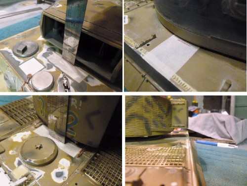
- Taking location measurents (Click for larger image )
N:BMake sure you take all these measurements of the STD location with the Turret ring drive gear screwed in place. This ensures the most accurate measurements or you will have some slack.
Line 1 is the position of the front of the Turret with the bin Flush with the Hull in its "correct" position .
Line 2 is the reference mark for side of Turret facing forward.
Line 3 is the position of the front of the Turret with the original bin hanging over the side.
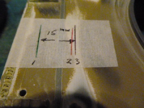
- Difference between correct and incorrect position front turret when turned 90 degree
As you can see the difference is 15mm , I have seen 13.5 and 14.5mm mentioned before on some posts, but I settled on 15mm as it looked correct.
NOTE : 2019 Update. 13.5mm is more accurate. See Hull correction.
3 -Screw a timber slat inside the Turret Base, this is 19x75mm on section
4 -Use posts circled to line up centre of the circle A, mark on tape the centre and 15mm "backset" B to rear
5 -Using a Jakar compass cutter placed in the centre point A, you score 3/4 through thickness (NOT FULLY)
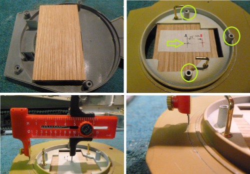
- Scoring out the Centre A ring ( Click for larger image )
Just make sure you take your time, firm pressure but not hard, cutting even sections at a time working around the circle a 1/4 circle at a time. Regular checks underneath until you see a very faint line in the under side and STOP Thanks to
Tanks-for-the-Memory for this method.
6 -Stop when you see this mark coming through.
7 -Now switch to Point B and working in the same method work on this crescent cut out until fully removed alternating with Point A.
8 -As you can see it removes with a nice clean edge.

- Point B offset cutting and removal (Click for larger image )
9 -Working back on Point A, score under these BB/Recoil mounting posts until fully through.
10-With a razor saw, cut under the ribs flush to disconnect them from your workings
11-Complete the full removal of centre section.
12-BB/Recoil mounts are left intact

- Completing the Circle A and under sawing BB/Recoil Mounts. (Click for larger images )
13-Crescent Section B is now moved to the rear
14-A few styrene tabs temporarily hold things in place.
15-You can see the original post mounts and how much the Turret have moved forward (Yes forward!)
16-With the Turret rotation gear back in place check it is now flush

- Swopping over Section A and B and checking allignment. ( Click for larger image )
17-Bond in sections of 0.25mm styrene to replace material under BB/Recoil mounting posts lost in sawing through.
18-Additional side tabs.
19-Main front and rear supports tabs 1.5mm styrene.
20-Turret main opening is now 15mm more toward the rear.
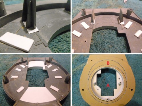
- Reinforcing from inside and completed swop of removed sections ( Click for larger image )
21-0.5mm Styrene plate added underneath
21-Ensure this extends flush with the outside profile of Turret Base. At this stage I removed the HL Bin base as I will be adding a Tamiya replacement which is the correct size and shape.
22-This is the Undercut / recess void to be filled with milliput.
23-Completed
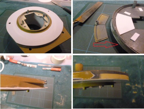
- Larger 0.50mm styrene plate bonded to reinforce bottom and used as template to fill undercut ( Click for larger image )
However, once back in place there is more work to do as the Turret whilst flush with the Hull when turned 90 degree it is now too far forward when the Turret faces front

- This is how far forward the whole Turret is moved forward without Part 2 correcting the Hull

- Turret Bin now correctly flush with Hull, but main Turret is too far forward. (Click for larger image )
.
Thanks for watching, Part 2 the "Hull " Correction to follow

.
Yesterday is our history, Tomorrow is an eternal mistery, Today is a gift, its why its called "The Present".
