Another Torro Pro-Metal King Tiger
Re: Another Torro Pro-Metal King Tiger
Great model! One of the best KT I have seen! 

Re: Another Torro Pro-Metal King Tiger
Thanks again to all for the comments, you are all too kind.
Anyway, my next item for attention is the rear armor, perhaps because i'm putting off tackling the upper hull just now which I know will be a lot of work
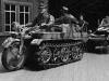
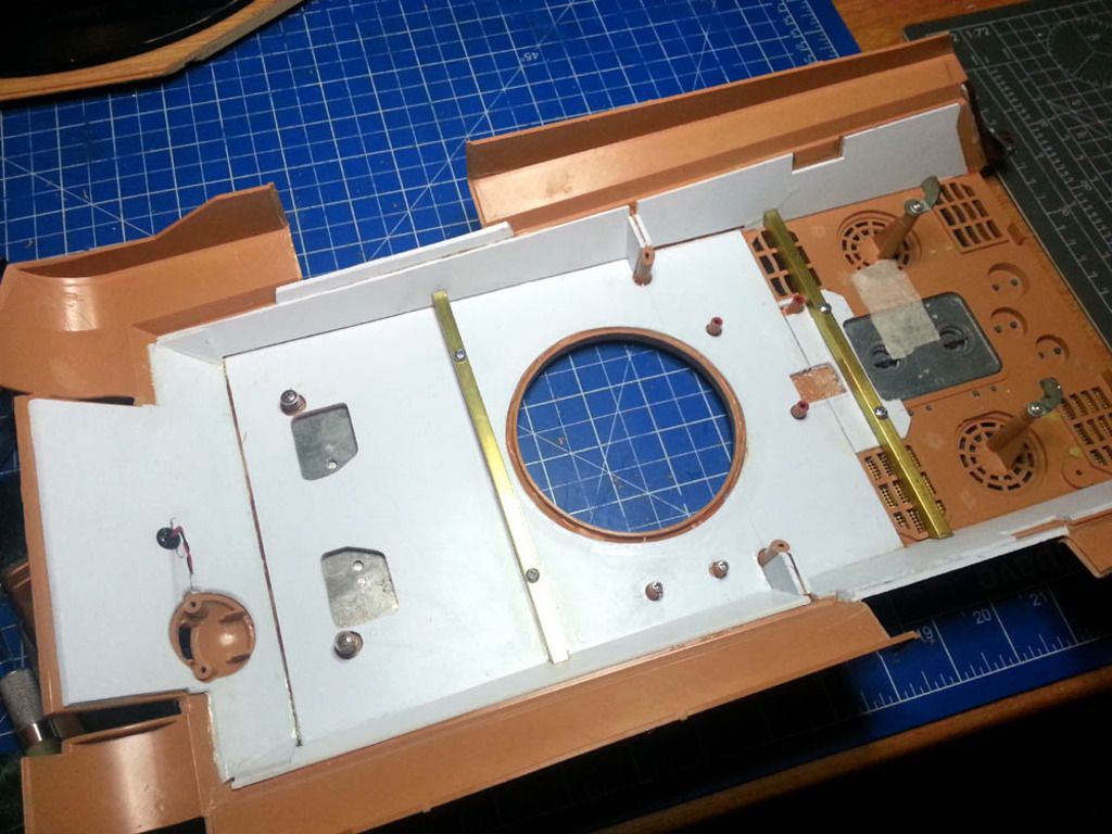
So, the stock rear end of the Torro KT arrives like so you will recall;
It is quite straightforward I found to strip down. I discarded entirely the stock rear fenders and the jack block which I intend to replace with the Aber photo etched parts or make myself. I retained parts of the jack itself and the C-hooks for later modification/upgrading;
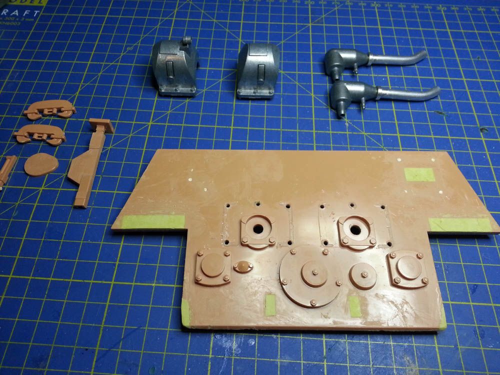
It can be see also (above pic) that I filled the recesses for the plastic rear fenders and jack mounts as well as the opening behind the jack block which was originally used for the main switch (as shown earlier I located this in a different place altgether). Also I have to repair the damage to bottom left and right corners which resulted from the exccesses of Torro's glue monkeys.
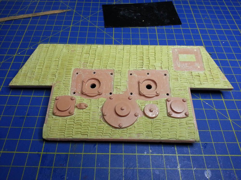
Next (pic below) I of course corrected another big mistake by Torro/Taigen which is to add the zimmerit couting to the rear armor plate. I don't understand why they zimmerit the side armor, front armor but not the rear. It is somewhat understandable in the case of the turret and lower glacis plate because these are metal, but not the rear armor (?)
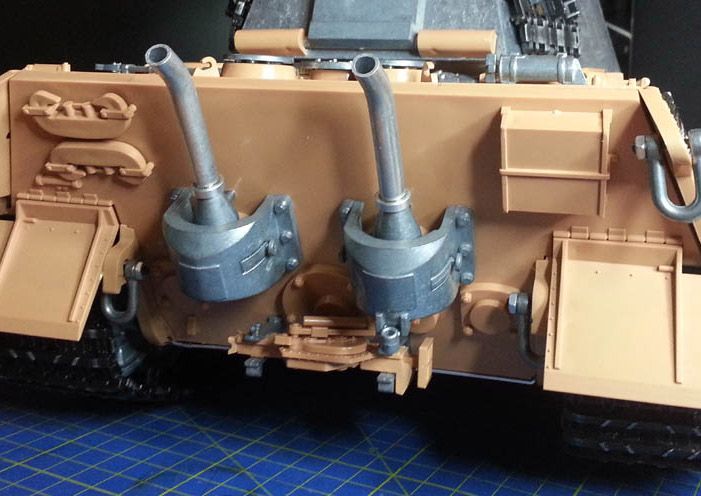
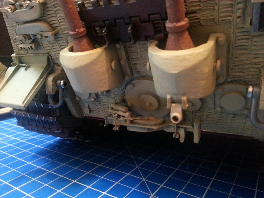
Anyway, zimmerit done I went on to correct the exhaust pipes angle, which was too pointing upwards. This I did (not shown) but making several cuts in the pipe, bending to desired angle and then soldering and sanding. I also added the anti-grenade bars (as I call them - see insert) to the pipe ends and prime. At this time I also add texture to the exhaust armor with Mr Surfacer along with the inspection and access covers.
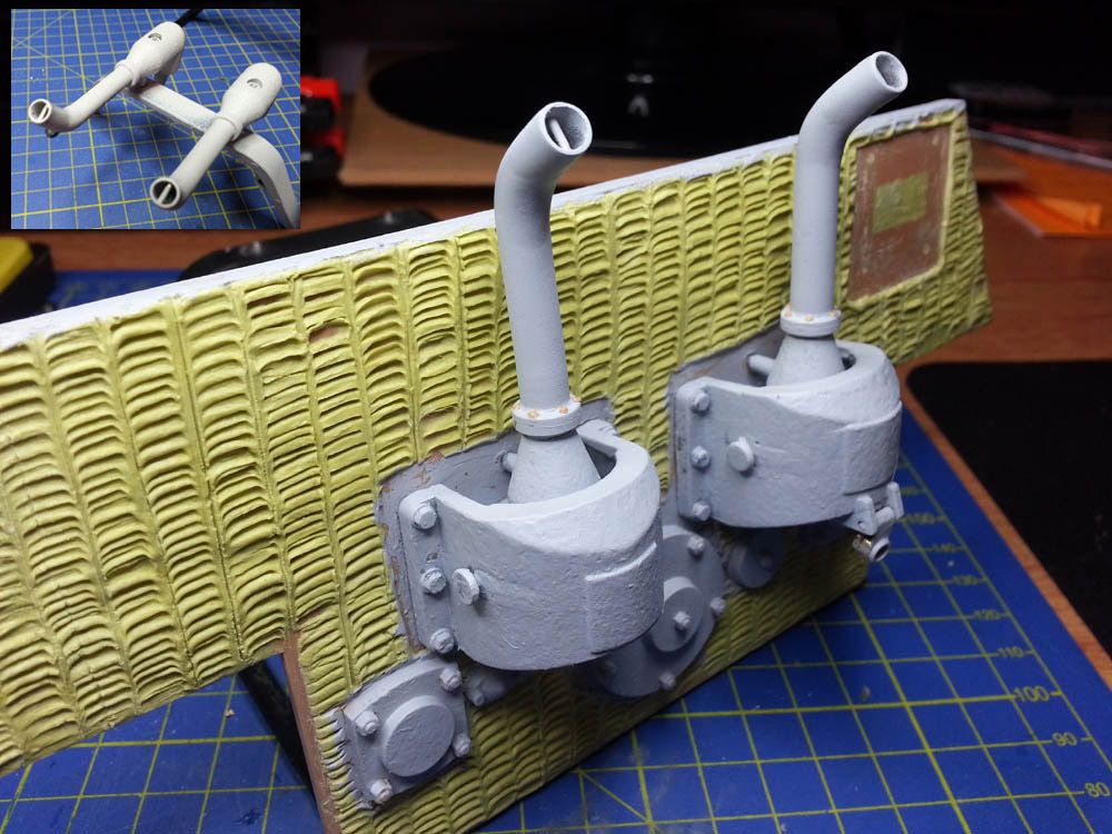
However, I then relised the shape on the exhaust armor (the little raised square) was wrong according to what others have done and the photos I have seen. So I removed, reworked, and resurfaced them to look correct. In addition it can be seen I added little extension tab each side to fill the gap Torro mistakenly left between the rear and side armor and it changed the flange bolts from six to four (my mistake) on the exhausts. Lastly here can be seen my first effort with the jack and mounts which wasn't good so later I reworked again;
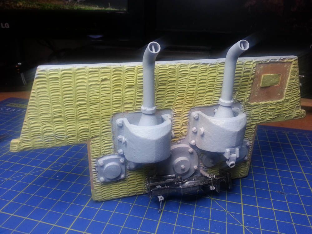
The next pic shows the addition of the completed photo-etched rear fenders, convoy light, C-hooks and holders, and the jack block which is constructed from matchsticks (see insert) . Yes, I know the original was one piece (hardwood I assume) so I intend to make it look one piece whilst retaining the wood grain I hope (my little indulgence ). Lastly I primered all excepting the accessories;

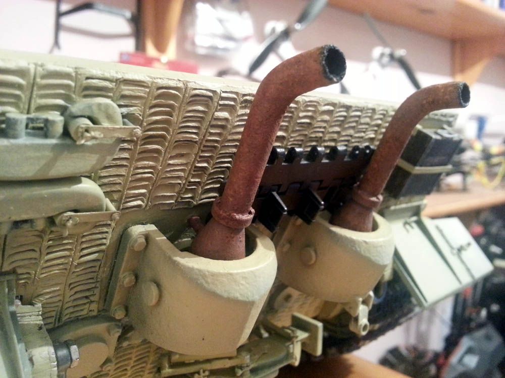
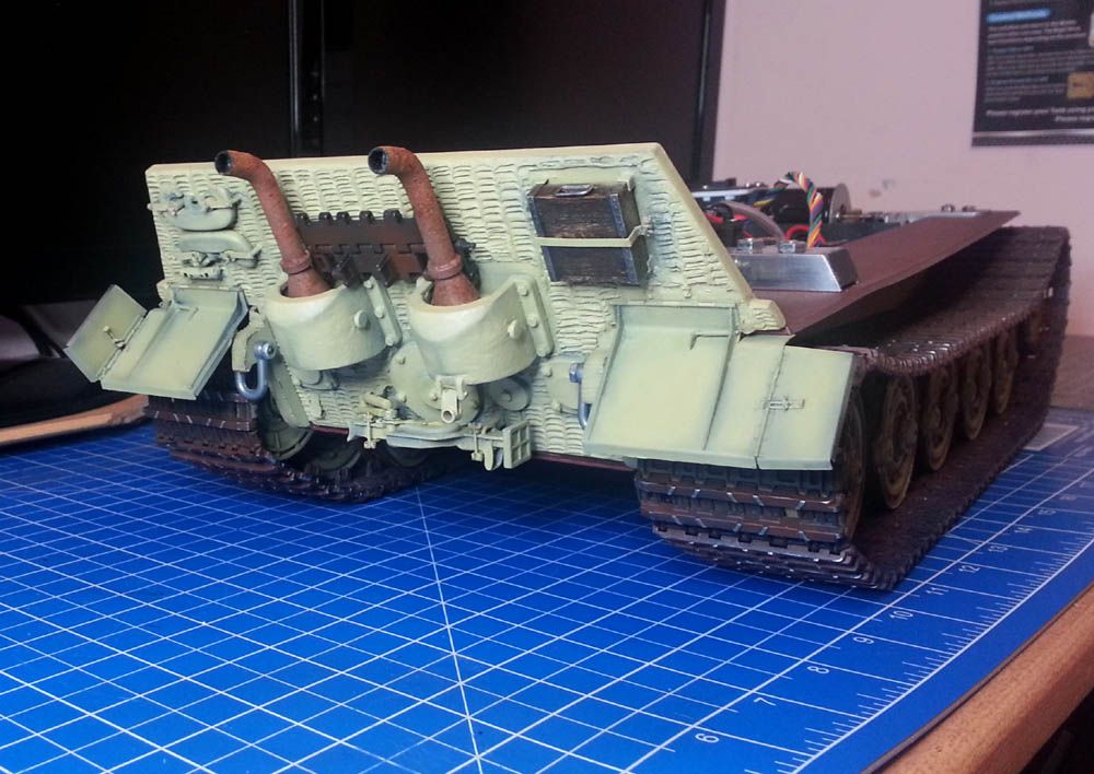
Finally, the next picture show the base coat with some pre-shading and rusting up the exhausts a little. I have left the jack block for now (as i say my little indulgence - I like the wood!) but the jack detail is now looking better I think. It still needs the two other camo colours and weathering, chipping, etc, but I hope it is heading in the right direction;
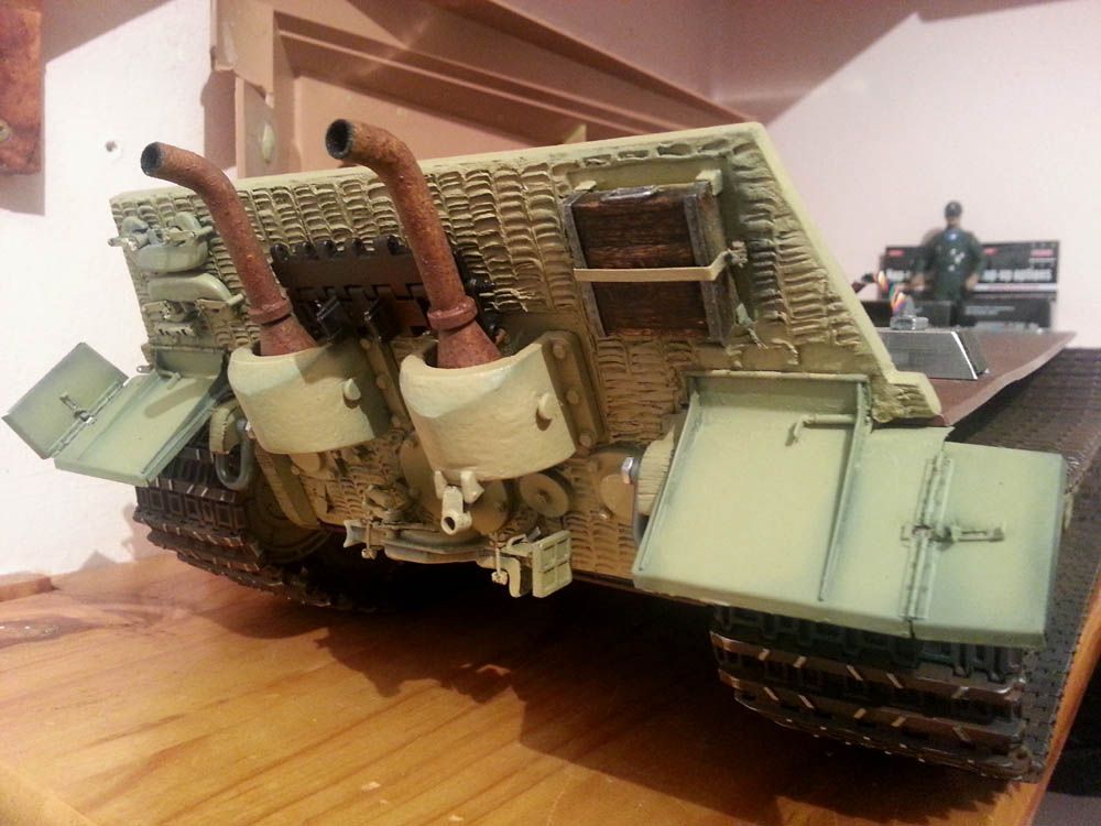
Apart from the camo coats the shackles are in need of colour and the addition of the obligatory hanging bucket of course I'll post again when finished. That's it for now though, next I will probably make a start on the tough bit - the upper hull - that should be some reall fun!!!
(p.s. if anyone has any queries then please do ask but, better still, if you have any advice then do please offer it!)
Anyway, my next item for attention is the rear armor, perhaps because i'm putting off tackling the upper hull just now which I know will be a lot of work
So, the stock rear end of the Torro KT arrives like so you will recall;

It is quite straightforward I found to strip down. I discarded entirely the stock rear fenders and the jack block which I intend to replace with the Aber photo etched parts or make myself. I retained parts of the jack itself and the C-hooks for later modification/upgrading;

It can be see also (above pic) that I filled the recesses for the plastic rear fenders and jack mounts as well as the opening behind the jack block which was originally used for the main switch (as shown earlier I located this in a different place altgether). Also I have to repair the damage to bottom left and right corners which resulted from the exccesses of Torro's glue monkeys.
Next (pic below) I of course corrected another big mistake by Torro/Taigen which is to add the zimmerit couting to the rear armor plate. I don't understand why they zimmerit the side armor, front armor but not the rear. It is somewhat understandable in the case of the turret and lower glacis plate because these are metal, but not the rear armor (?)

Anyway, zimmerit done I went on to correct the exhaust pipes angle, which was too pointing upwards. This I did (not shown) but making several cuts in the pipe, bending to desired angle and then soldering and sanding. I also added the anti-grenade bars (as I call them - see insert) to the pipe ends and prime. At this time I also add texture to the exhaust armor with Mr Surfacer along with the inspection and access covers.

However, I then relised the shape on the exhaust armor (the little raised square) was wrong according to what others have done and the photos I have seen. So I removed, reworked, and resurfaced them to look correct. In addition it can be seen I added little extension tab each side to fill the gap Torro mistakenly left between the rear and side armor and it changed the flange bolts from six to four (my mistake) on the exhausts. Lastly here can be seen my first effort with the jack and mounts which wasn't good so later I reworked again;

The next pic shows the addition of the completed photo-etched rear fenders, convoy light, C-hooks and holders, and the jack block which is constructed from matchsticks (see insert) . Yes, I know the original was one piece (hardwood I assume) so I intend to make it look one piece whilst retaining the wood grain I hope (my little indulgence

Finally, the next picture show the base coat with some pre-shading and rusting up the exhausts a little. I have left the jack block for now (as i say my little indulgence - I like the wood!) but the jack detail is now looking better I think. It still needs the two other camo colours and weathering, chipping, etc, but I hope it is heading in the right direction;


Apart from the camo coats the shackles are in need of colour and the addition of the obligatory hanging bucket of course
(p.s. if anyone has any queries then please do ask but, better still, if you have any advice then do please offer it!)
-
PainlessWolf
- Colonel
- Posts: 7782
- Joined: Sun Feb 26, 2012 9:09 pm
- Location: Southern Colorado Rocky Mountains
Re: Another Torro Pro-Metal King Tiger
Good afternoon, Doctor!
I really admire the detail work ( since that is where Heaven lies or so it is said ) The PE and the wooden jack block are top drawer! The bucket!, yes, obligatory! Following along.
regards,
Painless
I really admire the detail work ( since that is where Heaven lies or so it is said ) The PE and the wooden jack block are top drawer! The bucket!, yes, obligatory! Following along.
regards,
Painless
...Money!? What's that!?...
-
pedal2metal
- Private
- Posts: 63
- Joined: Wed Jun 13, 2012 12:56 am
- Location: Southern PA, USA
Re: Another Torro Pro-Metal King Tiger
Heading in the right direction?? I'd say HECK YEAH! I agree the block is so cool! I'll be keeping an eye on your build.
Re: Another Torro Pro-Metal King Tiger
Very nice build.
-
HERMAN BIX
- Major-General
- Posts: 11722
- Joined: Sun Jan 12, 2014 12:15 am
- Location: Gold Coast,Australia
Re: Another Torro Pro-Metal King Tiger
Any updates mate ?
Don't want this to go cold !
Don't want this to go cold !
HL JAGDPANTHER,HL TIGER 1,HL PzIII MUNITIONSCHLEPPER, HL KT OCTOPUS,HL PANTHER ZU-FUSS,HL STuG III,HL T34/85 BEDSPRING,
HL PZIV MALTA,MATORRO JAGDTIGER,HL F05 TIGER,TAMIYA KT,HL PANTHERDOZER,HL EARLY PANTHER G,TAIGEN/RAMINATOR T34/76,
HL AN-BRI-RAM SU-85
HL PZIV MALTA,MATORRO JAGDTIGER,HL F05 TIGER,TAMIYA KT,HL PANTHERDOZER,HL EARLY PANTHER G,TAIGEN/RAMINATOR T34/76,
HL AN-BRI-RAM SU-85
Re: Another Torro Pro-Metal King Tiger
No chance of going cold, but thanks for asking Herman. I'm too far into this hobby now for that (even got my next tank project, an all metal M36B1, sitting patiently in a shiny new box waiting for some attention - there's no hope for me now I reckon!)
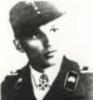
Well, I have been busy working on the upper hull mostly (where the most extensive work is I think required) but before that I did another small mod to the lower hull as follows. I noticed when field testing the hull that there was still a little flex in the rear lower metal tub, below the idler adjusters. Probably not a problem but to ensure no flex here too I added further a reinforcement, this time heavy brass square section that was relatively easy to fit but is extremely stiff;
And here a little closer;

The result is a now a super strong lower hull and on my test run over long grass, wet uneven grass, loose gravel. tree roots, and shallow inclines, it tracks perfectly, turns effortlessly and makes no attempt to shed its tracks - there is next to zero detectable play in the sprocket or idler shafts. This is with the stock Taigen 380 motors on the steel 5:1 gearboxes as seen earlier. It is relatively slow on these boxes (compared for instance to my recently acquired Sherman based M36B1) but this is as it should be I guess with this great lumbering giant of a tank!
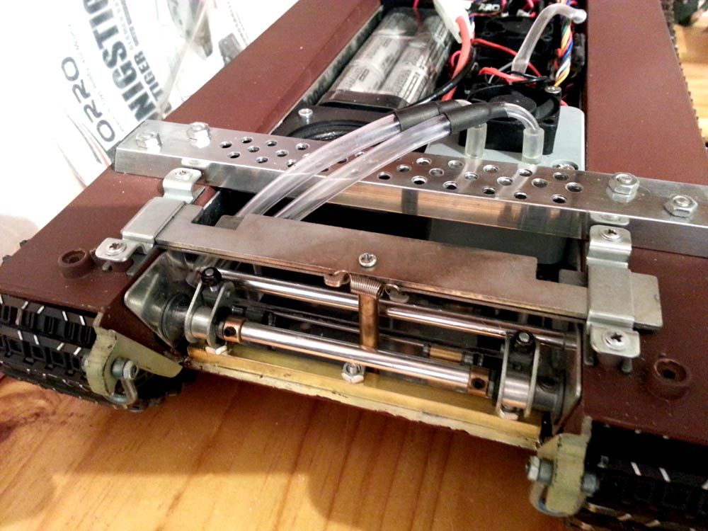
Anyway, returning to the upper hull I can only say oh dear! What have I got myself into? The following picture shows the stock hull as delivered and before work begun;
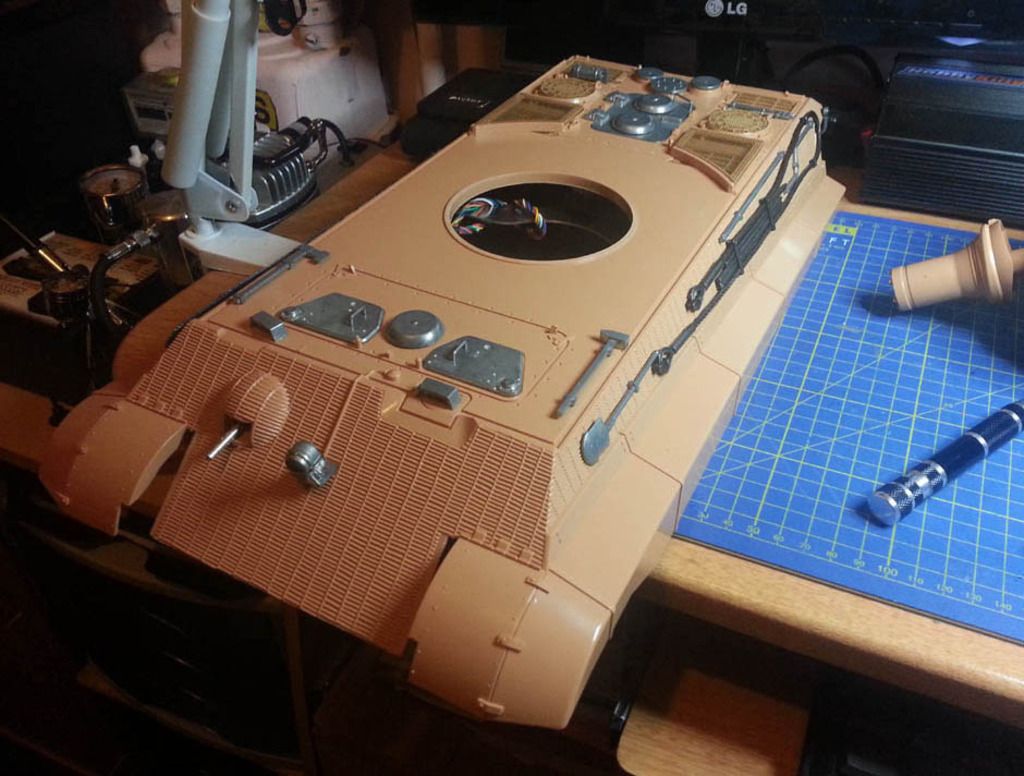
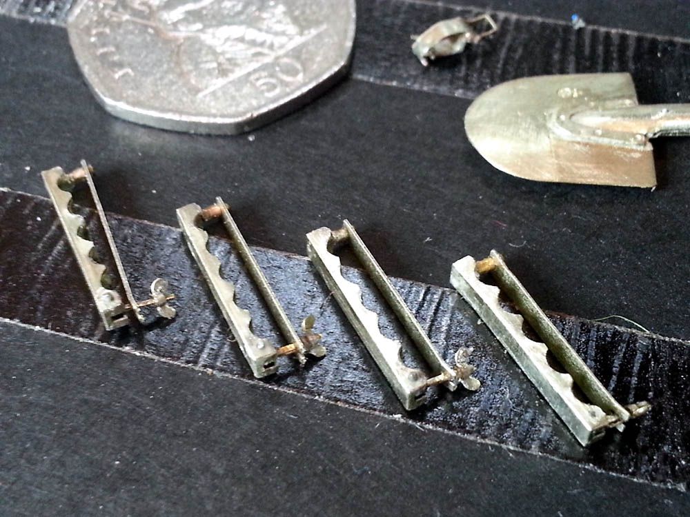
But my problem was I planned to add a lot of detail to this by way of the photo-etch kits available for the King Tiger. Fine, you might say, but I had no idea just how time consuming this part was going to be (remember I am still a newbie here - learning fast though! ). Working through the basic KT PE kit has been an education in itself (and long hours) but I eventually got a lot of parts ready;
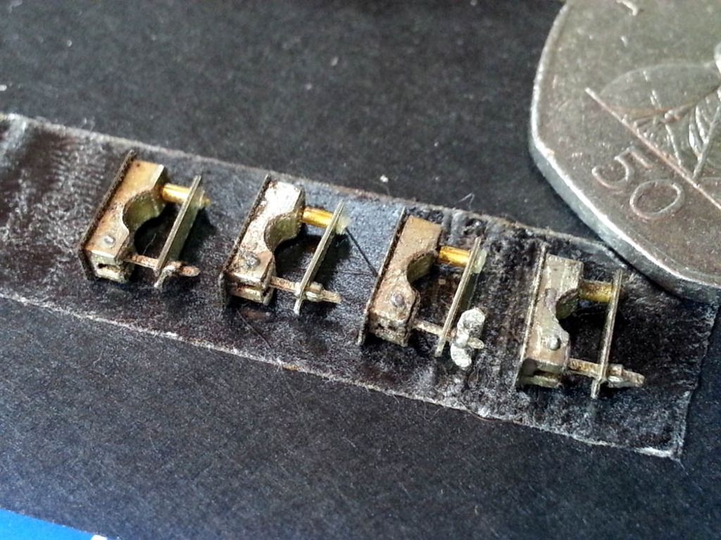
The soldering at this scale level has been a real challenge (and many swear words) and some is not as pretty as I would have like but I'm pleased every clasp, hasp, and clamp actually works as it should and would on the real thing;
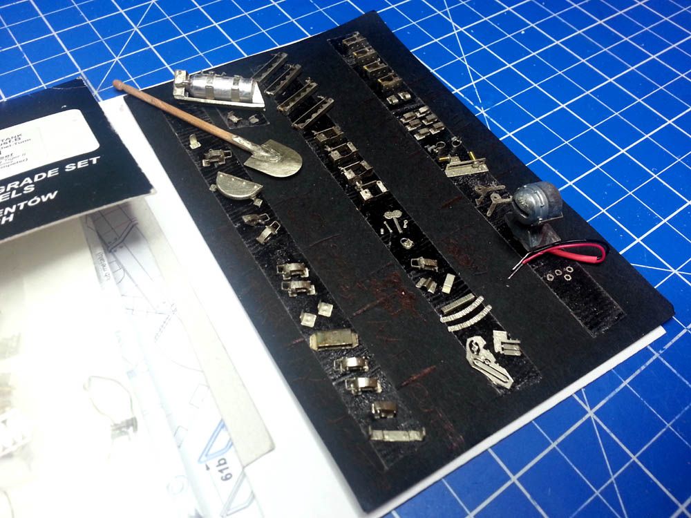
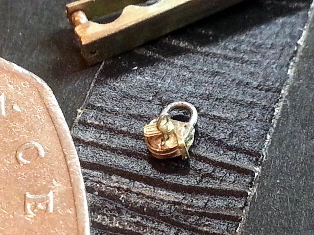
Which brings me to a query someone here might be able to help with. The following picture is of a tiny padlock I made which even has a key and keyhole cover (as can be seen) and whilst I am quite pleased with myself that I managed to get this together I have no idea what it is for? In fact there are two set of parts available for this but no indication in the assembly instructions regarding where it goes or what its for. Oh well, if anyone has any idea please do let me know;
So, back to the build and the upper hull. Having now taken a break from squinting continually through big fat diopter magnifying lens (whatever that is) I started on the hull by first adding some preliminary battle damage here and there;
In case other newbies are wondering, the trick I found is to use a sharp (I use scapel) knife to undercut the plastic zimmerit effect. I did consider a complete replacement with milliput to match my work on the turret but decided against this - at least for now. I'll see if I can get the desired effect with the plastic imitation first. Following this I begun reinforcing the rather flimsy hull generally. For this, and as other have, I used mainly 2mm styrene sheet and completely covered the inside of the armour plates, top sides and front glacis. This not only provides a much stiffer hull it also gives a more scale feel to what was, after all, some very very heavy metal! The exception, you will see, is the upper rear section which has open grill and so is not so easily reforced with the styrene in this way;
Two more features will be noticed here; 1) I have added brass reinforcement braces here too. This is heavy material but very stiff and adds further reinforcement for where the turret rests and the rear section that, as I mentions above is without additional thickness, and 2) cut-away side fender sections which can be seen further here (below);
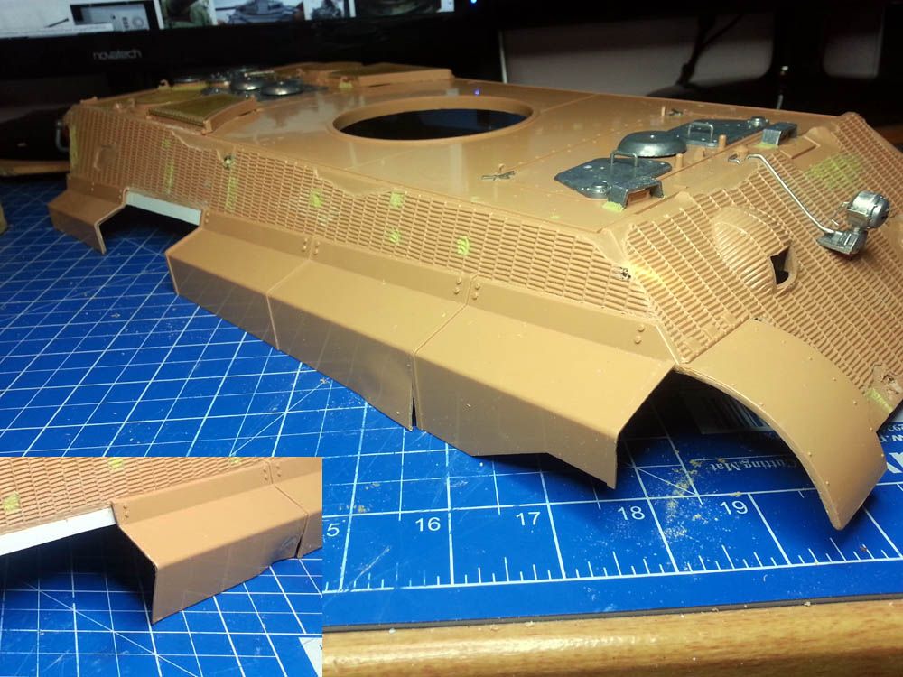
Notice also in the above picture that I have put bends and impact damage in the plastic side fenders in a further attempt to emulate some of the damage that appears typically to have been sustained by KTs in the field. Having now inspected many pictures what seems apparent is that often they lost or removed these side fenders but where they didn't they were strangely not showing a lot of the damage as is sometimes depicted. Hence my approach here. Also, in making these fender panels detachable I will have the option of displaying the tank with or without them. Incidentally, I opted not to go with the photo-etch replacement fender as, although better detailed, I want to keep these side fenders fairly robust for transporting and running outside.
Moving on to the outer shell of the upper hull I turned my attention to the engine hatch. This is missing some detail and I thought now is as good a time as any to sort that out;
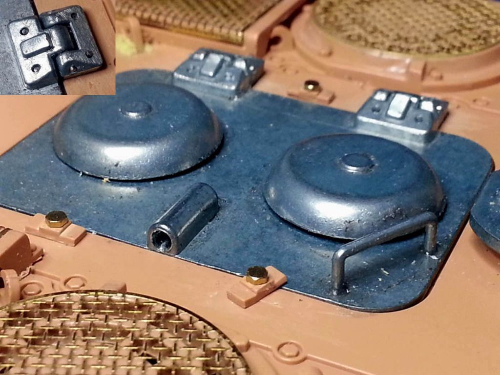
Here (and in the insert pic) can be seen the addition of bolt hole on the hinges and also I removed these and drilled the hinge through so as to insert a proper hinge pin which is missing of the Torro part. Similarly I drilled through the hatch lifting bar tube. The mod I am really happy with here however is the reworking of the three hatch securing latches which now have scale brass bolts and actually work as they should (the Torro hull has these as moulded on parts).
I have done a few other small bits and pieces (e.g. added weld seams, removed the molded aerial tube, and wrongly placed overflows from the engine compartment, etc) but for now that's about where I am with it. I'm looking forward to finishing the reinforcing and detailing so that I can get on with painting. In between I even make a little time for irritations like work
Well, I have been busy working on the upper hull mostly (where the most extensive work is I think required) but before that I did another small mod to the lower hull as follows. I noticed when field testing the hull that there was still a little flex in the rear lower metal tub, below the idler adjusters. Probably not a problem but to ensure no flex here too I added further a reinforcement, this time heavy brass square section that was relatively easy to fit but is extremely stiff;

And here a little closer;

The result is a now a super strong lower hull and on my test run over long grass, wet uneven grass, loose gravel. tree roots, and shallow inclines, it tracks perfectly, turns effortlessly and makes no attempt to shed its tracks - there is next to zero detectable play in the sprocket or idler shafts. This is with the stock Taigen 380 motors on the steel 5:1 gearboxes as seen earlier. It is relatively slow on these boxes (compared for instance to my recently acquired Sherman based M36B1) but this is as it should be I guess with this great lumbering giant of a tank!
Anyway, returning to the upper hull I can only say oh dear! What have I got myself into? The following picture shows the stock hull as delivered and before work begun;

But my problem was I planned to add a lot of detail to this by way of the photo-etch kits available for the King Tiger. Fine, you might say, but I had no idea just how time consuming this part was going to be (remember I am still a newbie here - learning fast though!

The soldering at this scale level has been a real challenge (and many swear words) and some is not as pretty as I would have like but I'm pleased every clasp, hasp, and clamp actually works as it should and would on the real thing;


Which brings me to a query someone here might be able to help with. The following picture is of a tiny padlock I made which even has a key and keyhole cover (as can be seen) and whilst I am quite pleased with myself that I managed to get this together I have no idea what it is for? In fact there are two set of parts available for this but no indication in the assembly instructions regarding where it goes or what its for. Oh well, if anyone has any idea please do let me know;

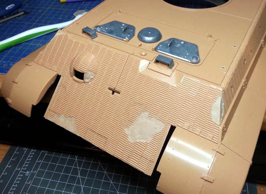
So, back to the build and the upper hull. Having now taken a break from squinting continually through big fat diopter magnifying lens (whatever that is) I started on the hull by first adding some preliminary battle damage here and there;

In case other newbies are wondering, the trick I found is to use a sharp (I use scapel) knife to undercut the plastic zimmerit effect. I did consider a complete replacement with milliput to match my work on the turret but decided against this - at least for now. I'll see if I can get the desired effect with the plastic imitation first. Following this I begun reinforcing the rather flimsy hull generally. For this, and as other have, I used mainly 2mm styrene sheet and completely covered the inside of the armour plates, top sides and front glacis. This not only provides a much stiffer hull it also gives a more scale feel to what was, after all, some very very heavy metal! The exception, you will see, is the upper rear section which has open grill and so is not so easily reforced with the styrene in this way;

Two more features will be noticed here; 1) I have added brass reinforcement braces here too. This is heavy material but very stiff and adds further reinforcement for where the turret rests and the rear section that, as I mentions above is without additional thickness, and 2) cut-away side fender sections which can be seen further here (below);

Notice also in the above picture that I have put bends and impact damage in the plastic side fenders in a further attempt to emulate some of the damage that appears typically to have been sustained by KTs in the field. Having now inspected many pictures what seems apparent is that often they lost or removed these side fenders but where they didn't they were strangely not showing a lot of the damage as is sometimes depicted. Hence my approach here. Also, in making these fender panels detachable I will have the option of displaying the tank with or without them. Incidentally, I opted not to go with the photo-etch replacement fender as, although better detailed, I want to keep these side fenders fairly robust for transporting and running outside.
Moving on to the outer shell of the upper hull I turned my attention to the engine hatch. This is missing some detail and I thought now is as good a time as any to sort that out;

Here (and in the insert pic) can be seen the addition of bolt hole on the hinges and also I removed these and drilled the hinge through so as to insert a proper hinge pin which is missing of the Torro part. Similarly I drilled through the hatch lifting bar tube. The mod I am really happy with here however is the reworking of the three hatch securing latches which now have scale brass bolts and actually work as they should (the Torro hull has these as moulded on parts).
I have done a few other small bits and pieces (e.g. added weld seams, removed the molded aerial tube, and wrongly placed overflows from the engine compartment, etc) but for now that's about where I am with it. I'm looking forward to finishing the reinforcing and detailing so that I can get on with painting. In between I even make a little time for irritations like work
-
HERMAN BIX
- Major-General
- Posts: 11722
- Joined: Sun Jan 12, 2014 12:15 am
- Location: Gold Coast,Australia
Re: Another Torro Pro-Metal King Tiger
Bravo, we are on again !
Lovn it
Lovn it
HL JAGDPANTHER,HL TIGER 1,HL PzIII MUNITIONSCHLEPPER, HL KT OCTOPUS,HL PANTHER ZU-FUSS,HL STuG III,HL T34/85 BEDSPRING,
HL PZIV MALTA,MATORRO JAGDTIGER,HL F05 TIGER,TAMIYA KT,HL PANTHERDOZER,HL EARLY PANTHER G,TAIGEN/RAMINATOR T34/76,
HL AN-BRI-RAM SU-85
HL PZIV MALTA,MATORRO JAGDTIGER,HL F05 TIGER,TAMIYA KT,HL PANTHERDOZER,HL EARLY PANTHER G,TAIGEN/RAMINATOR T34/76,
HL AN-BRI-RAM SU-85
-
Raminator
- Warrant Officer 2nd Class
- Posts: 1309
- Joined: Tue Aug 11, 2015 9:57 am
- Location: Newcastle, Australia
Re: Another Torro Pro-Metal King Tiger
Impressive work, Doctor. Your photoetch is amazing, I don't have keen enough eyes or a steady enough hand for that.
I took the same route reinforcing the upper hull of my T-34/76; 2 mm styrene sheet cemented in place and it's solid as a rock. I think I might have gotten carried away with it, though. We probably didn't need to go as far as we both have!
I took the same route reinforcing the upper hull of my T-34/76; 2 mm styrene sheet cemented in place and it's solid as a rock. I think I might have gotten carried away with it, though. We probably didn't need to go as far as we both have!
Re: Another Torro Pro-Metal King Tiger
Fantastic detail Doctor!!! Now for more realism add a nice acoustic smoker so you can see the engine produce smoke from idle pulse to roar.. and a great sound system! IBU3 based on what I have been reading about or TBS- which I have and totally love for amazing sound quality and ease of sound file creations.
