Hi,
Having just got my long awaited T55 I thought I would attempt to do a documented build. There are one or two of these already completed and others are under construction. Hopefully the builders will add to the thread and show how they did things because several heads are better than one and with luck we can end up with the definative T55 guide.
I can only describe how I do things myself to achieve what I want. Others will have different goals, different methods and more experience so please do let us all have the benefit of your input!
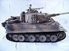
OK, first of all what do I want to create? There is a museum in Budapest called the House of Terror. Its a very sobering place and shows what the Hungarian people went through under both the Nazi regime and after the war under the Russian boot. They have a "T54" which supposedly took part in the suppression of the revolution in 1956. But the turret and hatches are the ones used with the nbc system introduced on the T55. But the T55 did not enter service till 1958 so this tank is really a fake! This fact, and its supposed part in Cold War history make it a tank worth modelling.
Much more to follow!
Peter
Hooben T55
-
forgebear
- Warrant Officer 1st Class
- Posts: 1848
- Joined: Fri Nov 21, 2008 11:15 pm
- Location: bedford
- Contact:
Re: Hooben T55
hi pete yes please need all the build info we can get thanks dave 
Re: Hooben T55
There is little to tell so far Dave. I've put the tracks together (boring job) and fitted the torsion blocks to the hull.
Regarding the torsion blocks, the screws that Hooben supplied are slightly too short to take the suggested washers and nuts. I haven't measured them, but by "rack of eye" I would guess they have put 6mm instead of 8mm in the bag.
What I have done is to omit the spring washers and use threadlock instead.
There are two reasons for this:
1. It saves me buying new screws
2. Spring washers should never be screwed up tight. If you do, they don't work very well. My opinion is that the firmer grip provided by a properly tightened, locktited screw will pull the torsion blocks fully up to the sides of the hull and help stiffen it. Possibly it is an illusion, but the hull does feel less floppy when everything is bolted up tightly.
Washers were used between the screw heads and the plastic to spread the loads a bit. I also put the screws on the hull sides in from the inside, not as Hooben suggest. My thinking for this is that even a huge nut which really should not be there looks less conspicous than a cross head screw. I may live to regret this decision, we will see what it looks like and what the clearances are when I get the wheels on!
Thats all for now. I've done some playing with the gearboxes and I will probably write that up tomorrow.
Peter
NOTE FROM THE FUTURE: PUTTING THE SCREW IN AS I HAVE SUGGESTED WILL WORK, BUT I FOUND WHEN I WAS FITTING THE SUSPENSION SPRINGS THAT BUYING LONG SCREWS AND PUTTING THEM IN THE "RIGHT" WAY ROUND IS ADVISABLE. EXTRA LENGTH CAN BE CUT OFF WITH A DREMEL ONCE YOU ARE SURE THAT YOU DON'T NEED THIS FOR FITTING ANYTHING ELSE SUCH AS STIFFENING ON THE INSIDE OF THE HULL.
Sorry if I have misled anybody. This is the sort of thing that can happen when writing about a build stage by stage and modding as you go.
Last edited by BigPanzer on Sat Nov 06, 2010 3:14 pm, edited 1 time in total.
Re: Hooben T55
OK folks, the tracks are together and the torsion blocks are fitted to the lower hull. I forgot to say this in my previous woffle, but the blocks are very nicely cast, with good sharp detail (new moulds of course) and they fit very well. The screw holes lined up very well.
Before I start on the gearboxes the motors themselves are worthy of comment. They are a Chinese version of the 380, but the design is different in that they have metal end caps.
They also have a supressor cap fitted to each terminal, but the leads on the caps are quite long and they are not fitted with insulating sleeves. A small point, but an important one as it would be very easy to create a short between the motor terminals and fry the ESC.
It was only a few minutes work to de-solder the caps, fit some sleeving over their leads and pop them back on. Watch when you do this job that you don't apply too much heat and melt the plastic insulator that separates the motor terminal from the metal end plate. And don't bend the terminal too much. If you break it you will have to buy a new motor.
I can't stress how important this job is. If not done it is so easy to inadvertantly press the naked cap leads against the motor casing and BANG!!
If you don't have soldering skills it would be possible to wrap a layer of bodge tape round the end of the motor.
The motor pinions are brass and seem very firmly attached to the shafts. No danger of these coming loose - at least, not on mine!
More on the gearboxes later
Peter
Re: Hooben T55
Gearboxes. As it used to say on my old school reports - could do better!
I found faults on both, so here we go:
The first two stages are plastic. The gear pairs rotate on a steel shaft. There is a pair of brass bushes fitted to each gear to give a decent bearing surface. I needed to get some Brasso and use it on the shaft and bush to get them to rotate freely. The bushes were tight on the shaft and the gears had been rotating on the static bushes.
Once the bushes were running freely I Locktited them in place in the gears using the shaft as a mandrel to make sure they were straight.
On one of the shafts the bushes had been so tight that they were causing the shaft to rotate in the frame!
The frames themselves are quite a soft alloy and I found on mine that the angles were not a true 90 deg, throwing some of the gears out of true mesh so I had to tweak the frames slightly to get them true.
What I found when I undid the countersunk screws in the base was not nice at all. They had been countersunk too deeply, causing the screw heads to start pulling through the metal. On one box this was so severe that the frame metal had deformed on the inside, causing the motor mount to sit badly.
Do watch out for this. Some boxes are probably OK, others definately not so.
The ideal solution is to drill new holes, tap them out and re-countersink, but not too deeply!
The output shaft runs in a pair of ball races, but the holes for them are over sized. This means that the bearings rotate in the hole. These need to be Loctited in place. However, I have not done this yet because I want to see how the output shafts line up with the final drive housings first.
I'm going to have my tea now and then see how the suspension goes together.
More later
Peter
Re: Hooben T55
I have just spent hours and hours playing with the suspension but its too late to write it up tonight. Before I go to bed though, a few more words on the gearboxes:
I found that when I examined them after I had test fitted the motor mounts following the drilling and countersinking of the new holes that the mesh of the motor pinion/1st gear was too deep. I filed the screw holes and bearing hole in the mount slightly oval and that fixed that problem. It didn't need much, under 0.5 mm, but it did make a difference to the"feel" of the box. If you have to do this on yours, don't over do it.
I didn't find any problems with the brass gears or their shafting.
When putting them back together I made sure all the bearing surfaces were clean, free and lightly lubed and I put a small drop of Locktite on each of the shafts where they go through the frame, making sure none spread to the inside of the frames and let it harden while I assembled my test rig.
My gearbox test rig consists of a 1.5v AA cell with a couple of wires soldered to it. If a gearbox will turn over smoothly, quietly and with a good amount of torque showing on the meter (finger and thumb) then its not bad. In this case they both seemed fine.
I test fitted the boxes and checked the hull for any twist on a glass chopping board after scraping the breadcrumbs off it and found there was no rocking.
Now all I have to do is remember to Locktite in the output shaft bearings when I fit the drive housings.
Goodnight all.
Peter
PS. I forgot to add, Matdragon and Septon have successfully fitted Tam Pershing boxes. There is a description on another thread. Interesting mod.
Re: Hooben T55
Hi,
Where is everybody? Whats happened to the other builders? Is anybody reading this? If so, do please stick your heads up and tell us what you are up to and how you are getting round problems.
The next stage attempted was the suspension and idlers, but first I have to go back to the tracks.
They do not look the strongest tracks in the world and I don't think they will last too long knowing the way that we abuse our models. The reason is that I think the very ends of the links will pull away from the pins. There is a web that prevents them spreading, but this is very thin and could soon wear or break.
Consequently this is a model that is absolutely crying out for metal tracks. These put more of a strain on idlers, roadwheels and final drive as well as the hull because the extra weight can cause the hull to twist more. So the model has to be capable of taking this extra stress, and I don't think Hooben have thought about this.
Firstly the hull.
Probably most of you are familiar with the WaSan T34 and the horrible track tension system. The Hooben works the same way, but the tensioner bits are in white metal and much more substantial. What I propose to do is to ball race the idlers and put a bit of stiffening in the front of the hull. I test fitted the idler system and put a bit of pressure on the idlers. Sure enough, the hull bent inwards at the front so I cut a bit of 3/16 x 3/4 ally strip to 4.25" long, made sure the ends were square and that it was a light friction vertical fit inside the hull just forward of the two pillars for the hull top securing screws. Leave a couple of mm or so gap between the pillars and the strip (In case they have to be reinforced with bits of tube at a later date) and make sure there is clearance to get a spanner on the tension adjusting nuts. I then ran a drop of superglue round the edge to hold it in place temporarily.
A personal note here. I build my own battery eliminator circuits using an LM317 regulator. This bit of ally might well provide the ideal heat sink for the regulator so I filed a semicircle out of the bottom of the stiffening strip so I could get the wires through.
Next I mixed up some Araldite - the 3 day stuff, strongest glue I have and ran a fillet around the 3 edges that were in contact with the hull. This is currently curing in the airing cupboard.
I did think it might be advisable to use screws as well, but having examined it after curing this might not be required.
The other weak point I've spotted is the point where the idler axle shaft is fixed to the tensioner. The tensioner is only white metal and I'm concerned that a crack might develop there so what I propose to do it to cut a bit of brass tube (diameter large enough to fit over the sleeve section of the idler) to the length of the sleeve, drill a clearance hole in it for the shaft securing screw and Araldite it on to the idler sleeve. It would also be very easy to strip the thread in the white metal, so use Locktite and don't over tighten.
I must apologise here - one pic is worth a thousand words. 'Er in drawers has given me permission to go and buy a camera so you might be able to make more sense of my ramblings with photos.
Now to the idlers themselves. Hooben supply a single bronze bearing clamped between two halves of a white metal idler. Again I don't see this lasting too long so I propose supergluing the two halves of the wheel together without the bush, drilling these assemblies right through and fitting flanged sealed bearings. (Technobots).
It will be neccessary to counterbore the wheels slightly on the outside to fit the standard axle shaft and fit the plastic hub cap. A shallow counterbore might also be required on the inside to fit a washer between the bearing and the wide bit on the tensioner.
Regrettably I can't give a fuller description of fitting the idlers. The bearings won't arrive till Tuesday, but by the end of next week I should be able to report on my efforts to fit them and the roadwheels.
More to follow. The next epistle will be about the fitting of the movable bits of the suspension.
Peter
Last edited by BigPanzer on Sat Nov 06, 2010 3:23 pm, edited 2 times in total.
-
forgebear
- Warrant Officer 1st Class
- Posts: 1848
- Joined: Fri Nov 21, 2008 11:15 pm
- Location: bedford
- Contact:
Re: Hooben T55
thanks pete i am takeing this all in mate for when i do mine
dave
dave
Re: Hooben T55
Hi, First of all, and with apologies, a couple of corrections to by previous scribblings.
When I was fitting the suspension torsion blocks I commented about Hoobens screws being too short and suggested fitting the screws the wrong way round. If your screws are too short, sod the expense and go buy some that are over length. The additional length is required to secure the suspension springs.
I will be re-fitting the 20 screws that secure the blocks to the sides of the hull. I also think it would be easier when fitting these springs if the screws were inserted the correct way around. Extra length can be cut off with a Dremel once you are certain this extra length is not required for fitting possible stiffening plates or anything else. The screws in the underside of the hull are fine.
The second point is the stiffening plate fitted yesterday. Having taken it out of the airing cupboard just now I find that it is really well stuck and I don't think the drilling, tapping and screwing will be required. But just to be certain I will put another fillet of the slow setting Araldite on the other side of it, then decide.
I have corrected the text I wrote about the stiffening member and put a note on my earlier post re: screws.
Apologies if I have misled anybody. It just goes to prove I am not a T55 guru!
Thanks for the encouragement Dave!
Peter
Re: Hooben T55
Suspension.
Note that parts are handed, but that the handing is reversed on some of the wheels so look at the diagram in the manual carefully, sort out all the bits you need and put the right bits to make up each sub assembly in a separate compartment in your egg box or whatever you use.
The suspension looks pretty substantial. It consists of a white metal torsion block fitted to the hull. Through this goes a swing axle. On the inboard end of the swing axle is a coiled torsion spring. The spring fits around the axle and one end of it engages in a slot. The other end has an eye on it which is fixed under one of the torsion block securing screws.
Further inboard, but still within the torsion block casting there is a limiter, also in white metal which stops the assembly rotating too far in either direction. On the inboard end of the limiter there is a peg which fits into a hole in the end of the torsion block casting.
The whole assembly is prevented from coming apart by a rather horrible little wire circlip that is a sod to fit.
Check the swing arms carefully for any traces of flash and remove any found with a fine file. Take off the minimum and finish off with some fine wet/dry used dry. Don't forget to clean out any from the circlip grooves with a bit of junior hacksaw blade.
Now select each swing arm for best fit in the torsion block hole. You will probably find that they will fit better in some blocks than others. Mark the pairs with a scriber or pencil.
Now check that the springs will fit over the spring arms easily, that the end will fit into the slot and that its coils do not bind on the swing arm as you tighten and slacken it. I found one spring was so small in diameter it would not fit over any of the swing arms and had to part unroll it and rewind it. Not an easy job!
Check that each swing arm will fit easily and fully into the socket in the limiter.
Check that you haven't mixed up any of the bits!
Now that you have checked everything and rectified all the minor niggles the whole thing should go together quite easily - maybe!
It can only be done one way:
Lightly grease the swing arm and insert it into the correct hole about halfway.
Lightly grease the peg on the end of the limiter and pop it into the hole in the back of the torsion block.
Take the spring in a pair of small pliers and feed it in between the swing arm and the limiter block. Make sure you have got it the right way round (eye towards the hull side) and gently lower the swing arm through the spring coils. Rotate until the end of the spring engages in the slot in the end of the swing arm (making sure the swing arm is not 180deg out) and and poke the spring up the shaft, engaging the swing arm in the limiter block as you do so. Hooben say to epoxy the ends of the swing arms into the limiter blocks, but I haven't done this. If you do you will never get the thing apart should you need to. The fit is quite tight anyway. If you don't, the assembly is marginally weaker. The choice is yours!
Now for the entertaining bit - the circlip. You did remember to clean out the groove, right? If not, you might regret it shortly!
Using the finest pliers you have or strong fine tweezers pick it up by the middle. Move the eye end of the suspension spring as far out of the way as you can, push the spring as far up the shaft as you can, lay the circlip on the side of the torsion block and wiggle the shaft until the clip starts to go home then give it a firm push. Now pick it up from the bottom of the torsion block and try again. Soon you will get the knack, hopefully before you lose any of them completely.
Now if you can, rotate the clip in its groove so that the open side points downwards when the swing arm is somewhere near its normal operating position. If you don't do this one end of the clip is likely to get pushed off by the end of the spring that is fixed to the torsion block, it will pop off and you might lose a wheel.
The front and rear roadwheels have linkage on them to represent a shock absorber. These are easy enough to assemble and fit, but look out for iffy threads. One stripped on assembly, forcing me to find some longer screws and nuts, but otherwise no comment needed.
If I was building a model for really serious hammering I might consider omitting these and fill the holes in the hull because they are only there to look good and are part hidden by the wheels.
There is very little in the way of adjustment on this type of suspension, which is one reason why I don't like it very much. There are two settings (depending on which torsion block screw you use) but short of changing the springs there is little you can do to it without major surgery. A better system would be an inboard crank arm and a tension spring would be better, more compliant and easier to tune, but it would also take up more space in the hull.
Until I know how the layout of the internal gubbins I don't want to sacrifice any space, but it has gone on my list of probable mods.
There is a definite market here for uprated, well made springs here, particularly fore those who like to build heavy models.
I'm going to knock it on the head for tonight and go do a bit more building. Next time I will describe the entertainment I had fitting the sprockets and gearboxes.
Cheers
Peter
Last edited by BigPanzer on Tue Nov 09, 2010 2:30 am, edited 1 time in total.
