(in 1/72) the "Earlier" LVT-2

Got any static model tanks? If so post them here.
Post Reply
User avatar
Cpl O
Recruit
Posts: 17
Joined: Sat Jul 21, 2012 12:43 am
Location: Florida, USA

(in 1/72) the "Earlier" LVT-2

Post by Cpl O »

Well the whole time I was working on the LVT(A)-2.....
the LVT-2 was in the back of my mind.
My biggest draw back has been....the engine deck.
How do I do the engine deck?
I thought about strips of styrene...but I would go insane.
So I started diging trough the few kits I have......
wondering if I could find a substitute.
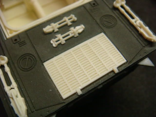
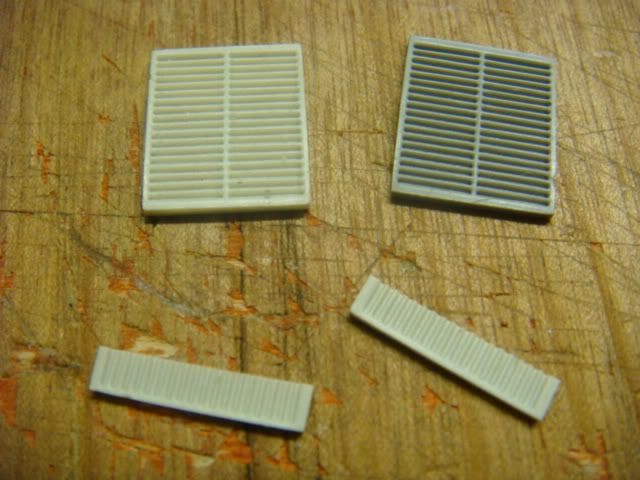
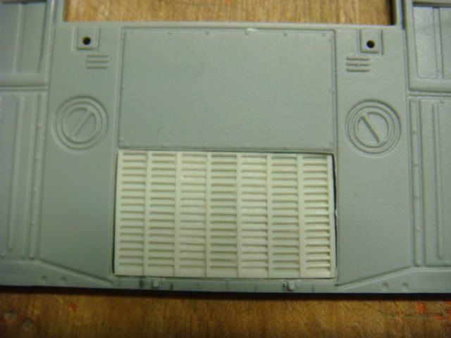
The best I could find was the center grill of the Elefant.
But how to make it work?
I only had one....but what to do?
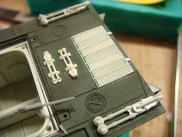
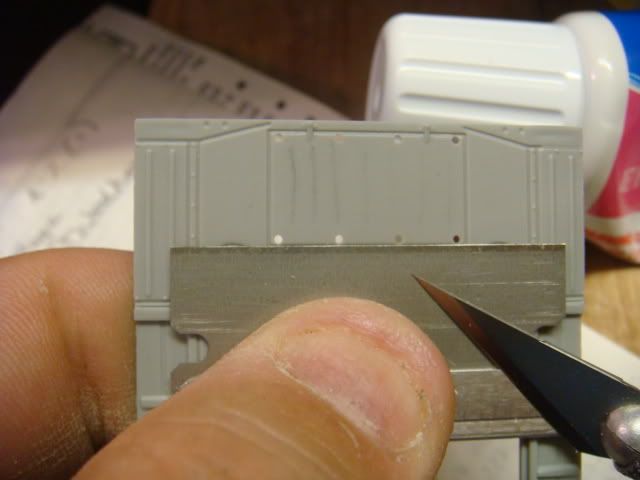
So I molded it, made copies, and cut it into strips.
Image

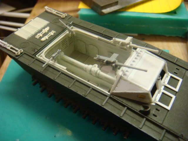
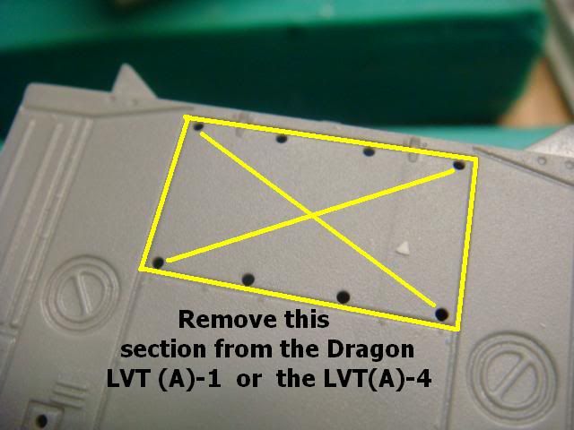
Then I looked at the engine deck area decided what to do, and cut it out.
Image

Image

Image

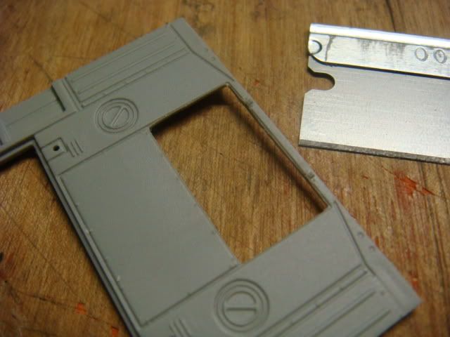
I started gluing the grill strips together.
Image

Image

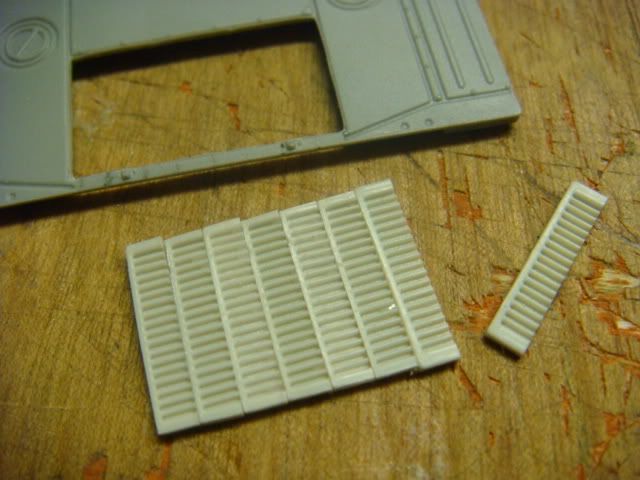
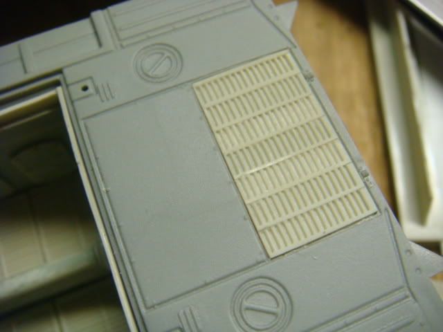
Then I test fitted it over and over again.
Image

Image


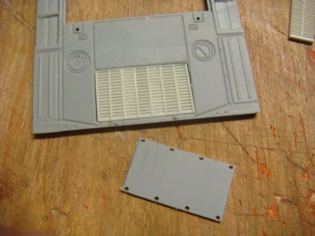
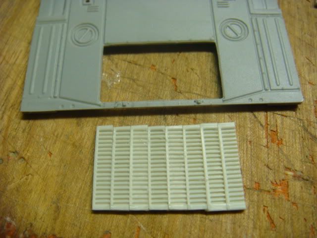
I then glued strip styrene to the back of it to give it support,
and glued it in place with elmers White glue.
Image

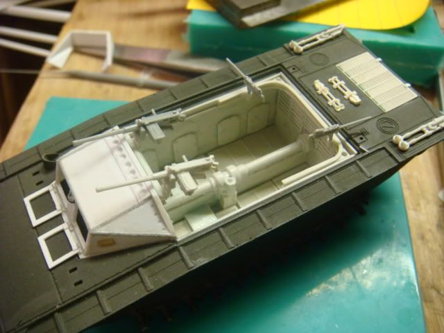
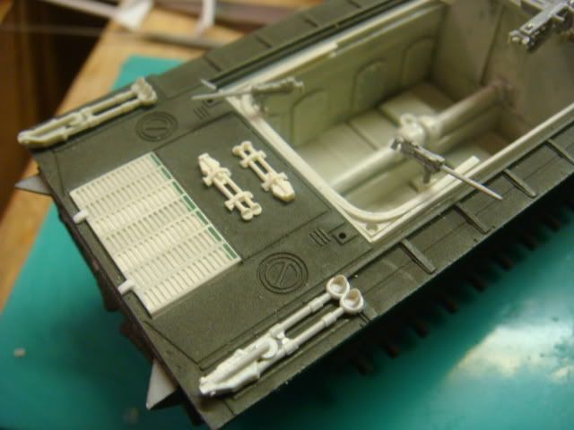
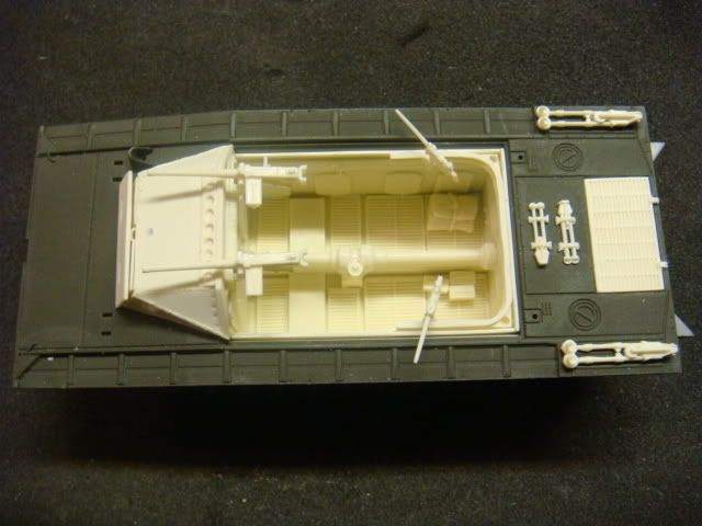
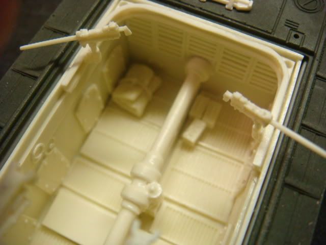
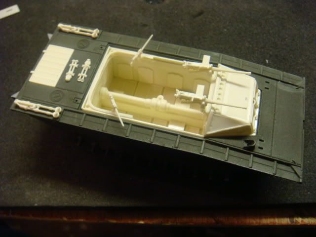
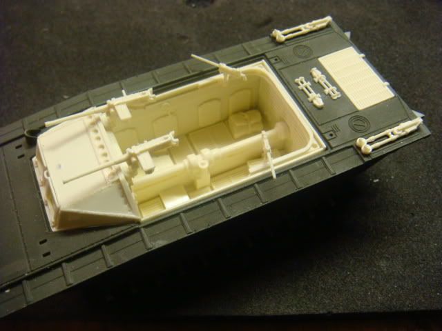
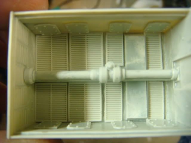
Now I turned my attention to the tub.
Now....the LVT-2 had "wood-slat" platforms on the floor.
So I again turned to the Elefant engine deck for my needs (I now have plnty of them).
Image

A couple (here and there) I need to cut to size.
Image

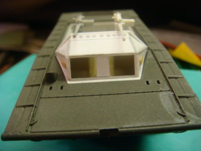
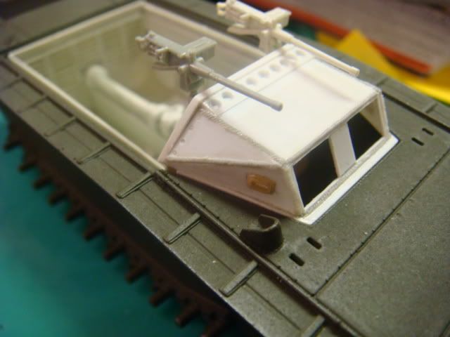
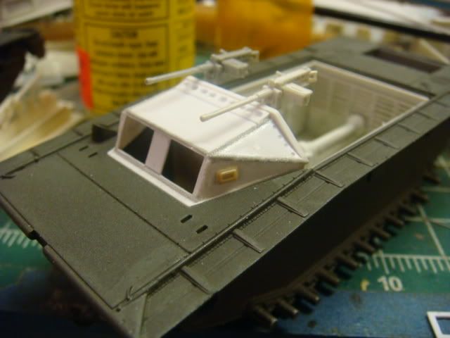
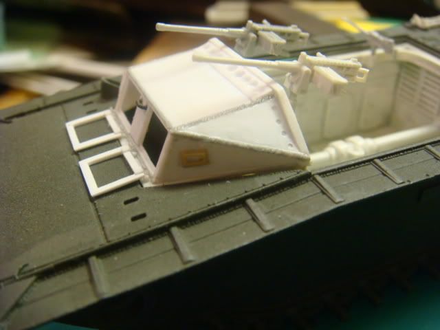
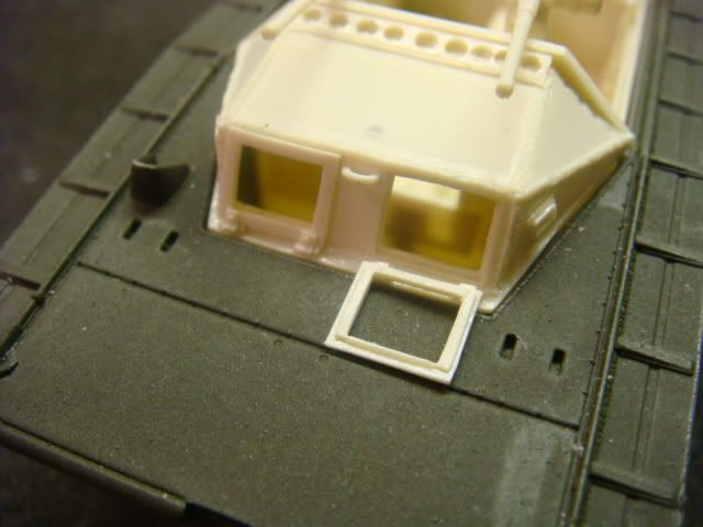
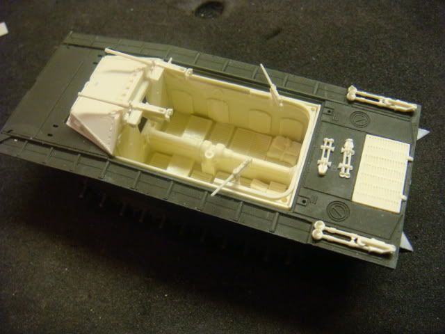
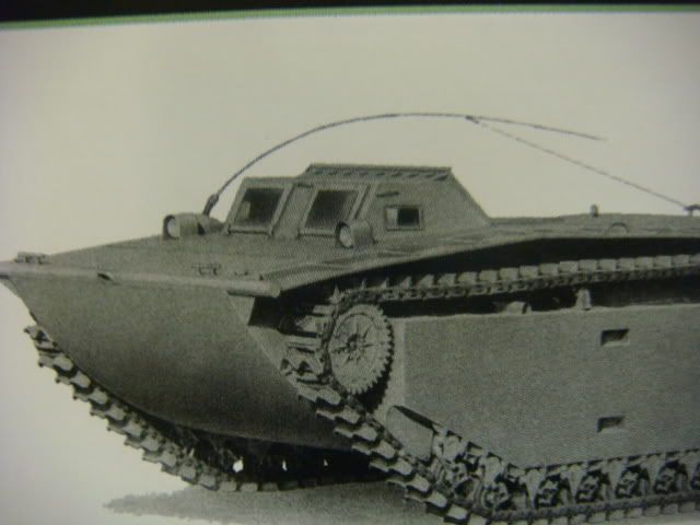
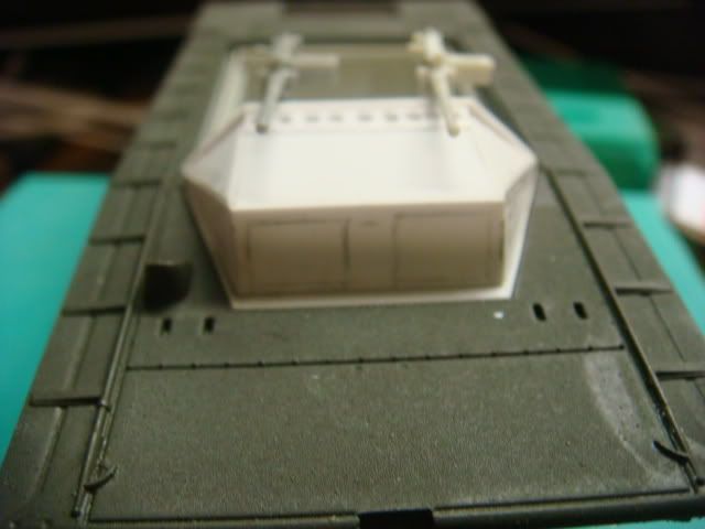
Now I am turning my attention to the cab.
Image

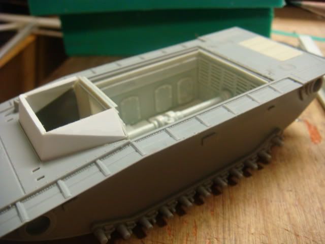
This is what it needs to look like.
Image

Image

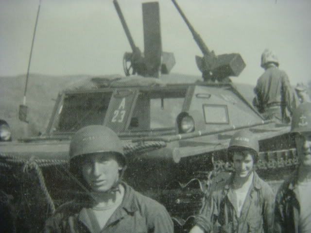
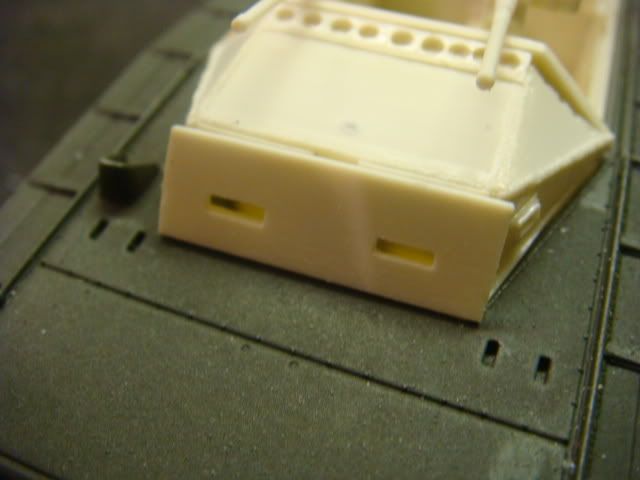
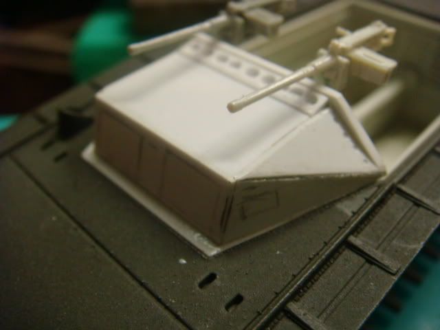
The skate rail will be a simple matter of just cutting it shorter.
So that is what I'll do there.
Well back to work.
(couple days later)

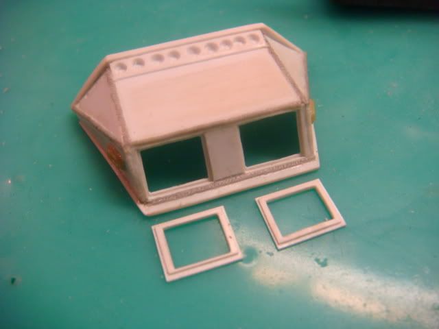
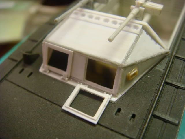
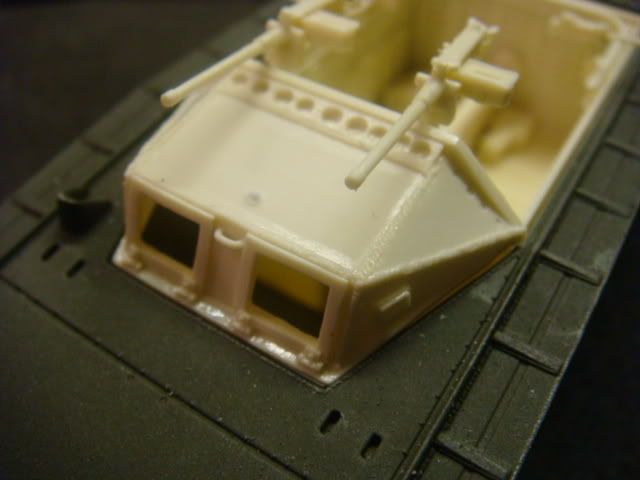
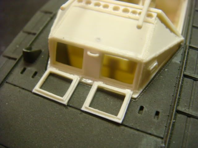
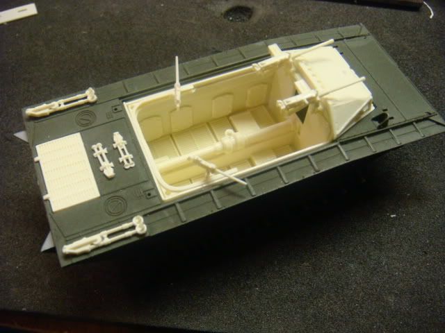
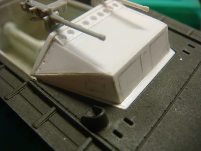
Today has been spent on making the cab.
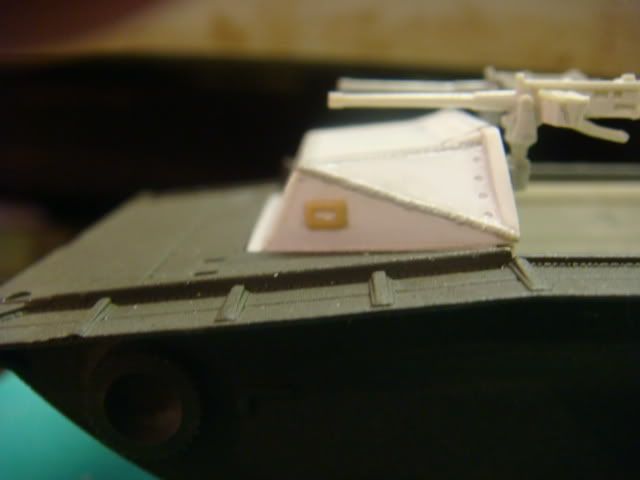
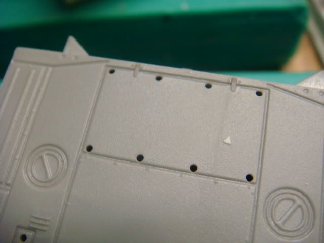
I know that I will need to cut off the windshield, and addd a little more slant to it.
Image

Image

Image

Image

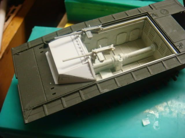
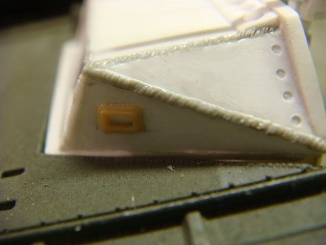
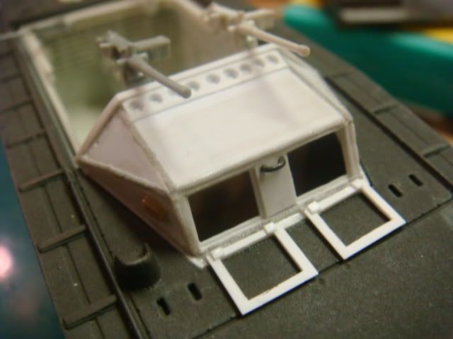
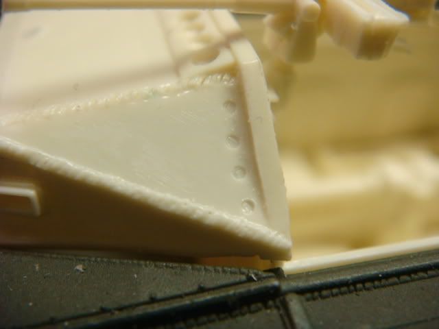
One of the things I am proud of are my "counter-sunk" screws.
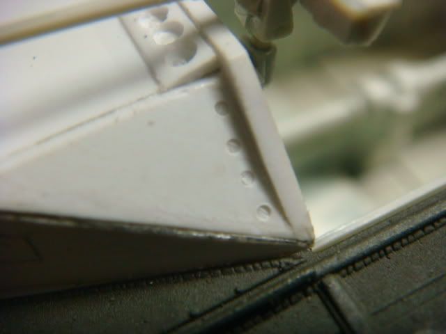
Image

As I said
I know I need to adjust the angle of the front so I'll get started on that.
User avatar
Cpl O
Recruit
Posts: 17
Joined: Sat Jul 21, 2012 12:43 am
Location: Florida, USA

Re: (in 1/72) the "Earlier" LVT-2

Post by Cpl O »

OK...here we go again....
I got the front windows cut out
(what were they thinking, oh well it's the "early" model so I guess they learned from here)
Image

I also added weld beads (I know this looks awfly thick, I'll thin it down before molding)
The weld beads were done by heating and stretching Drogn sprue to as thin as possible,
laying them in place, and soaking them with "Tenax-7R".
Once they were soft, I took a new sharp #11 blade and poked them till I got the desired pattern.
For the side windows, I used the view ports from ESCI's M12 SP.
Image

As you can see by this view I finally (also) got the angle of the front corrected.
Image

Here are a few views from other angles to see it better.
Image

Image

By this view you can see that I added a support rib to the "in side" of the windows,
and I got the window "flaps" done.
I had planned on putting "clear" plastic in these but we'll see how it goes.
Image

I still have to put the "Hindge Pinots" on the windws, and a little more work here and there....
I hope to have this all ready for molding by the end of the day.
User avatar
Cpl O
Recruit
Posts: 17
Joined: Sat Jul 21, 2012 12:43 am
Location: Florida, USA

Re: (in 1/72) the "Earlier" LVT-2

Post by Cpl O »

OK,
All the parts are ready for set-up to pouring the rubber.
It will have (2) .50 cals w/tripods, (2) .30 cals w/tripods.
Short(er) skate rail, front windows that can be opened (or closed).
The two (rear) MG mounts can be placed anywhere on the skate rail.
Image

Image

Image

Image

Image

Image

Image

My next post will be of the parts from the molds.
User avatar
Cpl O
Recruit
Posts: 17
Joined: Sat Jul 21, 2012 12:43 am
Location: Florida, USA

Re: (in 1/72) the "Earlier" LVT-2

Post by Cpl O »

OK she's all done....
but before I show you all the pic's here's a reminder.
You must first remove the engine deck.
Image

Here is what it looks like all assembled.
Image

One of the things that I'm proud of is that the front windows can be opened:
Image

Image

Image

I even provided the Field Mod armor plate for the front as an optional piece:
Image

Another thing that I am particularly proud of is my "Counter Sunk" screw detail.
Dragon got this all wrong on their kits, they molded them as rivets (Incorrect).
I missed it on my A-4 conversion, but corrected it on my A-1.
Image

Here is a look at the engine deck implaced:
Image

Here are the "few" stowage items that I included:
Image

And so here are a few views of it over all:
Image

Image

Image

Image

So this is up and running.
Post Reply

Return to “Tanks”