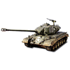
1/16 RC USMC M-60A1 Patton tank with ERA - Build

Re: 1/16 RC USMC M-60A1 US tank with ERA - Build
That is going to be a great looking tank. Love the recoil on the video.
"Don't believe everything you see on the internet" - George S. Patton
Eric
Eric

Re: 1/16 RC USMC M-60A1 US tank with ERA - Build
Thanks Eric
The following posts are for the mantlet canvas cover.
Its tempting to say that the canvas cover will be hidden behind the ERA blocks and to simply forget about it. However, from reference pictures, its partially true but there is still plenty of it visible.
For a rivet counter like me, it is worth a try. Replicating the mantlet cover in RC is complicated, can be discouraging and results can be dissapointing.
With the material available at our scale, its almost impossible to accurately replicate the fine canvas material, the shape and the foldings, while keeing it realisic and with functioning RC gun elevation. Sometimes, it is better to forget about it because its for not everyone, just like Tamiya did with the 1/16 Centurion and leave it in plastic.
I gave it a try and hoped for the best. I have previous experience with the Centurion Sho't Kal build. The plan was to do something similar.
View of the Academy kit mantlet canvas cover above and under the gun. Notice that the canvas has some rod structure underneath that keeps the canvas from going everywhere when the gun is raise and lowered.
For canvas material, i use Javex latex cleaning gloves purchased at the dollar store. It's elastic properties makes it a forgiving material regarding gun elevation.
As per Herman suggestion during the Centurion build, the back texture is better. It is actually perfect. A section larger than what is required is taken from one glove. It is not easy to cut however, which means it is strong as well...
A hole the size of the mantlet is made.
To prevent the canvas from going everywhere when the gun is raised and the canvas is folding, i provided a very basic 0.8mm brass rod structure underneath.
Positioning these correctly is however complicated and i had to redo it twice as you can see, there was originally too much canvas material between the tip and the hole. Anyway, its under and does not show.
The cavas is pulled over the mantlet to test the cut. That was before i put in the rods.
I started to glue the top attachment to the turret rim that was previously cleaned up of the fake bolts and sanded smooth, and then going down. The gluing to the mantlet is kept to the end.
The canvas is glued to the turret and to the mantlet extremities. Folding the canvas at strategic points is mandatory, and this needs to be done while you are elevating the gun up and down to check that everything is good. Now the excess material can be cut from the sides and below, up to a point.
Continuing on following post.
The following posts are for the mantlet canvas cover.
Its tempting to say that the canvas cover will be hidden behind the ERA blocks and to simply forget about it. However, from reference pictures, its partially true but there is still plenty of it visible.
For a rivet counter like me, it is worth a try. Replicating the mantlet cover in RC is complicated, can be discouraging and results can be dissapointing.
With the material available at our scale, its almost impossible to accurately replicate the fine canvas material, the shape and the foldings, while keeing it realisic and with functioning RC gun elevation. Sometimes, it is better to forget about it because its for not everyone, just like Tamiya did with the 1/16 Centurion and leave it in plastic.
I gave it a try and hoped for the best. I have previous experience with the Centurion Sho't Kal build. The plan was to do something similar.
- 1/16 RC USMC M-60A1 US tank with ERA - Build
- Screenshot 1.jpg (228.67 KiB) Viewed 2073 times
View of the Academy kit mantlet canvas cover above and under the gun. Notice that the canvas has some rod structure underneath that keeps the canvas from going everywhere when the gun is raise and lowered.
- 1/16 RC USMC M-60A1 US tank with ERA - Build
- Screenshot 2 .jpg (183.4 KiB) Viewed 2073 times
For canvas material, i use Javex latex cleaning gloves purchased at the dollar store. It's elastic properties makes it a forgiving material regarding gun elevation.
- 1/16 RC USMC M-60A1 US tank with ERA - Build
- Screenshot 3.jpg (259.52 KiB) Viewed 2073 times
As per Herman suggestion during the Centurion build, the back texture is better. It is actually perfect. A section larger than what is required is taken from one glove. It is not easy to cut however, which means it is strong as well...
- 1/16 RC USMC M-60A1 US tank with ERA - Build
- Screenshot 4.jpg (255.27 KiB) Viewed 2073 times
A hole the size of the mantlet is made.
- 1/16 RC USMC M-60A1 US tank with ERA - Build
- Screenshot 5.jpg (260.29 KiB) Viewed 2073 times
To prevent the canvas from going everywhere when the gun is raised and the canvas is folding, i provided a very basic 0.8mm brass rod structure underneath.
- 1/16 RC USMC M-60A1 US tank with ERA - Build
- Screenshot 5a.jpg (161.71 KiB) Viewed 2073 times
Positioning these correctly is however complicated and i had to redo it twice as you can see, there was originally too much canvas material between the tip and the hole. Anyway, its under and does not show.
- 1/16 RC USMC M-60A1 US tank with ERA - Build
- Screenshot 5b.jpg (163.78 KiB) Viewed 2073 times
The cavas is pulled over the mantlet to test the cut. That was before i put in the rods.
- 1/16 RC USMC M-60A1 US tank with ERA - Build
- Screenshot 6.jpg (158.1 KiB) Viewed 2073 times
I started to glue the top attachment to the turret rim that was previously cleaned up of the fake bolts and sanded smooth, and then going down. The gluing to the mantlet is kept to the end.
- 1/16 RC USMC M-60A1 US tank with ERA - Build
- Screenshot 7.jpg (184.25 KiB) Viewed 2073 times
The canvas is glued to the turret and to the mantlet extremities. Folding the canvas at strategic points is mandatory, and this needs to be done while you are elevating the gun up and down to check that everything is good. Now the excess material can be cut from the sides and below, up to a point.
- 1/16 RC USMC M-60A1 US tank with ERA - Build
- Screenshot 8.jpg (201.69 KiB) Viewed 2073 times
Continuing on following post.
Last edited by lmcq11 on Sun May 21, 2023 12:03 am, edited 1 time in total.
Re: 1/16 RC USMC M-60A1 US tank with ERA - Build
Raising and lowering the gun is required all the time to make sure nothing is blocking the elevation and that the canvas follows. The canvas is strong enough that correcting some mistakes is possible before the superglue is fully set, up to a point. After a few seconds, you have to live with whatever just happened. I think the canvas realistically folds on top and on the sides when the gun is raised and lowered. There is not too much excess material. Cannot hope for too much. The elasticity of the latex glove material prooves to be quite valuable and forgiving. The foldings are of the same style as on the plastic mantlet, which is important for a good integration of the look and feel.
The canvas is cut.
The retainer on the turret is made of 2mm brass strip with M1 hex brass bolts. The bolts are a bit too large but a M0.8 is too small and weak to screw into the turret to hold the strip in place, the bolts would break. The retainer replicates and is helpint to hold the canvas like the real thing, but the strip is also required to hide the joint imperfections.
A 0.8mm brass rod will serve as the joint on the mantlet, and also hide imperfections in the canvas cutting. It takes a bit of effort to make it follow the contour of the mantlet. Plastic rods would break at the corners. Keep in mind that cutting the latex is difficult. Can only be done with a new blade and even then.
The mantlet joint and some putty is applied. '
And here we have a M-60A1 mantlet canvas cover.
Close up providing detail on the texture and feel of the canvas material used.
Continuing on following post
- 1/16 RC USMC M-60A1 US tank with ERA - Build
- Screenshot 9.jpg (229.7 KiB) Viewed 2071 times
The canvas is cut.
- 1/16 RC USMC M-60A1 US tank with ERA - Build
- Screenshot 10.jpg (171.05 KiB) Viewed 2071 times
- 1/16 RC USMC M-60A1 US tank with ERA - Build
- Screenshot 11.jpg (181.06 KiB) Viewed 2071 times
The retainer on the turret is made of 2mm brass strip with M1 hex brass bolts. The bolts are a bit too large but a M0.8 is too small and weak to screw into the turret to hold the strip in place, the bolts would break. The retainer replicates and is helpint to hold the canvas like the real thing, but the strip is also required to hide the joint imperfections.
- 1/16 RC USMC M-60A1 US tank with ERA - Build
- Screenshot 12.jpg (237 KiB) Viewed 2071 times
A 0.8mm brass rod will serve as the joint on the mantlet, and also hide imperfections in the canvas cutting. It takes a bit of effort to make it follow the contour of the mantlet. Plastic rods would break at the corners. Keep in mind that cutting the latex is difficult. Can only be done with a new blade and even then.
- 1/16 RC USMC M-60A1 US tank with ERA - Build
- Screenshot 13.jpg (166.56 KiB) Viewed 2071 times
The mantlet joint and some putty is applied. '
And here we have a M-60A1 mantlet canvas cover.
- 1/16 RC USMC M-60A1 US tank with ERA - Build
- Screenshot 13b.jpg (208.2 KiB) Viewed 2071 times
Close up providing detail on the texture and feel of the canvas material used.
- 1/16 RC USMC M-60A1 US tank with ERA - Build
- Screenshot 13c.jpg (209.63 KiB) Viewed 2071 times
- 1/16 RC USMC M-60A1 US tank with ERA - Build
- Screenshot 13d.jpg (220.02 KiB) Viewed 2071 times
- 1/16 RC USMC M-60A1 US tank with ERA - Build
- Screenshot 14.jpg (221.83 KiB) Viewed 2071 times
- 1/16 RC USMC M-60A1 US tank with ERA - Build
- Screenshot 15.jpg (178.71 KiB) Viewed 2071 times
Continuing on following post
Last edited by lmcq11 on Sun May 21, 2023 12:18 am, edited 8 times in total.
Re: 1/16 RC USMC M-60A1 US tank with ERA - Build
The mantlet will be finetuned once the putty is dry and i have a cooler head. Not bad for a few hours on a cloudy saturday.
The model as it stands today. Overall, i am happy with the results. It is a best effort. Elevation works fine. Success... it is a load off.
I will have to make some tests to determine the best paint to apply on the canvas.
Regards, Louis
- 1/16 RC USMC M-60A1 US tank with ERA - Build
- Screenshot 17b.jpg (183.06 KiB) Viewed 2071 times
The model as it stands today. Overall, i am happy with the results. It is a best effort. Elevation works fine. Success... it is a load off.
I will have to make some tests to determine the best paint to apply on the canvas.
- 1/16 RC USMC M-60A1 US tank with ERA - Build
- Screenshot 18.jpg (222.48 KiB) Viewed 2071 times
Regards, Louis
Re: 1/16 RC USMC M-60A1 US tank with ERA - Build
Smart work in the canvas mantlet cover. Finishes it off nicely!
-
Herr Dr. Professor
- Major
- Posts: 6030
- Joined: Mon Apr 22, 2019 10:48 pm
- Location: Southern Wisconsin USA
Re: 1/16 RC USMC M-60A1 US tank with ERA - Build
I am impressed by the canvas cover on the M60. (A Dollar Store was just built in the town closest to where I live. I thought I would never have reason to go there. Well, I see a reason now.)
I believe that the slightly oversized bolt heads will be far less noticeable when painted. I wonder, too, if their size could be disguised if you were to use a wash over details on the rest of the tank, but leave the bolt heads alone. You continue to amaze me with your museum quality work.
I believe that the slightly oversized bolt heads will be far less noticeable when painted. I wonder, too, if their size could be disguised if you were to use a wash over details on the rest of the tank, but leave the bolt heads alone. You continue to amaze me with your museum quality work.
Re: 1/16 RC USMC M-60A1 US tank with ERA - Build
Hi, thank you for the encouragements !
A small update on the canvas cover.
When the canvas is positioned normally along the mantlet, the bottom smashes directly into the side bins. I had tested elevation during the installation of the canvas but i did not think of checking the rotation, assuming that it was no problem. For sure, the material is thicker than scale and the bolt heads were not originally trimmed. So, i had to reposition the bottom a bit higher and trim the bolt heads to clear the bins, by about 0.5mm...
In this picture, you can see the original position and the new one. Lessons learned.
This situation made me run a check on turret rotation all around the hull. I am noticing that the back corners of the turret actually hit the rear engine deck on the edges... I am thinking that the model turret is probably 0.5mm or 1mm too low. I'll probably have to raise it a bit or work on that edge a bit.
I was curious and checked the Academy 1/35 to see what was the clearance. The whole bottom of the turret actually slides on top of the deck, scraping it all the way on every turn... Oh boy, the clearance on the real tank must be really tight. Even the 1/35 kit makers cannot figure it out.
Now, the following posts are for the headlights and guards.
I have shown this picture before. It is full on information on the structure of the guard.
Frontal view of the M-60A1. I am noticing that the white light is on the same side for left and right headlight. Notice the curve on those guards, they are tricky. They look pretty round here.
But when looked at from a slightly different angle, then they seem to have a different shape. The interior side looks a lot more strait than on the previous picture. Same for all other pics, those guards can look different on every picture but they are the same. Much study is required.
Close up on the headlight.
The Tongde headlight are cleaned up and made ready to accept a 5mm LED, a white one that will be activated, and a dummy blue one that will fill the hole for the dark one. The holes are enlarged a bit.
The LEDs are trimmed to fit the holes.
Continuing on following post
A small update on the canvas cover.
When the canvas is positioned normally along the mantlet, the bottom smashes directly into the side bins. I had tested elevation during the installation of the canvas but i did not think of checking the rotation, assuming that it was no problem. For sure, the material is thicker than scale and the bolt heads were not originally trimmed. So, i had to reposition the bottom a bit higher and trim the bolt heads to clear the bins, by about 0.5mm...
- 1/16 RC USMC M-60A1 US tank with ERA - Build
- Screenshot 0a.jpg (158.23 KiB) Viewed 1945 times
In this picture, you can see the original position and the new one. Lessons learned.
- 1/16 RC USMC M-60A1 US tank with ERA - Build
- Screenshot 0b.jpg (214.09 KiB) Viewed 1945 times
This situation made me run a check on turret rotation all around the hull. I am noticing that the back corners of the turret actually hit the rear engine deck on the edges... I am thinking that the model turret is probably 0.5mm or 1mm too low. I'll probably have to raise it a bit or work on that edge a bit.
- 1/16 RC USMC M-60A1 US tank with ERA - Build
- Screenshot 0c.jpg (125.78 KiB) Viewed 1945 times
I was curious and checked the Academy 1/35 to see what was the clearance. The whole bottom of the turret actually slides on top of the deck, scraping it all the way on every turn... Oh boy, the clearance on the real tank must be really tight. Even the 1/35 kit makers cannot figure it out.
- 1/16 RC USMC M-60A1 US tank with ERA - Build
- Screenshot 0d.jpg (162.85 KiB) Viewed 1945 times
Now, the following posts are for the headlights and guards.
I have shown this picture before. It is full on information on the structure of the guard.
- 1/16 RC USMC M-60A1 US tank with ERA - Build
- Screenshot 1.jpg (144.74 KiB) Viewed 1945 times
Frontal view of the M-60A1. I am noticing that the white light is on the same side for left and right headlight. Notice the curve on those guards, they are tricky. They look pretty round here.
- 1/16 RC USMC M-60A1 US tank with ERA - Build
- Screenshot 2.jpg (435.49 KiB) Viewed 1945 times
But when looked at from a slightly different angle, then they seem to have a different shape. The interior side looks a lot more strait than on the previous picture. Same for all other pics, those guards can look different on every picture but they are the same. Much study is required.
- 1/16 RC USMC M-60A1 US tank with ERA - Build
- Screenshot 3.jpg (238.88 KiB) Viewed 1945 times
Close up on the headlight.
- 1/16 RC USMC M-60A1 US tank with ERA - Build
- Screenshot 4.jpg (437.5 KiB) Viewed 1945 times
The Tongde headlight are cleaned up and made ready to accept a 5mm LED, a white one that will be activated, and a dummy blue one that will fill the hole for the dark one. The holes are enlarged a bit.
- 1/16 RC USMC M-60A1 US tank with ERA - Build
- Screenshot 5.jpg (461.79 KiB) Viewed 1945 times
The LEDs are trimmed to fit the holes.
- 1/16 RC USMC M-60A1 US tank with ERA - Build
- Screenshot 6.jpg (390.13 KiB) Viewed 1945 times
Continuing on following post
Re: 1/16 RC USMC M-60A1 US tank with ERA - Build
A new cover is prepared.
All the back holes are filled with scrap plasticard and superglue that will be sanded for a smooth finish.
Frontal view but i am deciding to rework the details on the mount.
The headlights are finished. They look better without being perfect but they will do the job and did cost nothing extra.
Headlights are re-installed.
Everything around them is cleaned up in preparation for the creation of the guards.
Close up of an M60 headlight guard from the Verlinden book. Very useful for this build.
The base is redone using the AFV-Club kit for specs. Be aware that the mud guards need 2.5mm added to them at the front.
Material for the two supports are that go over the fenders are made of plasticard plates that add up to 4.5mm in thickness.
The supports are slowly created using a nail file. It takes about 20 minutes each by constantly checking the integration with the hull as they are refined.
Supports are installed over the fenders, looking good.
Continuing on following post
- 1/16 RC USMC M-60A1 US tank with ERA - Build
- Screenshot 7.jpg (316.22 KiB) Viewed 1943 times
All the back holes are filled with scrap plasticard and superglue that will be sanded for a smooth finish.
- 1/16 RC USMC M-60A1 US tank with ERA - Build
- Screenshot 8.jpg (346.81 KiB) Viewed 1943 times
Frontal view but i am deciding to rework the details on the mount.
- 1/16 RC USMC M-60A1 US tank with ERA - Build
- Screenshot 9.jpg (345.4 KiB) Viewed 1943 times
The headlights are finished. They look better without being perfect but they will do the job and did cost nothing extra.
- 1/16 RC USMC M-60A1 US tank with ERA - Build
- Screenshot 10.jpg (222.76 KiB) Viewed 1943 times
Headlights are re-installed.
- 1/16 RC USMC M-60A1 US tank with ERA - Build
- Screenshot 11.jpg (208.08 KiB) Viewed 1943 times
Everything around them is cleaned up in preparation for the creation of the guards.
- 1/16 RC USMC M-60A1 US tank with ERA - Build
- Screenshot 12.jpg (140.48 KiB) Viewed 1943 times
Close up of an M60 headlight guard from the Verlinden book. Very useful for this build.
- 1/16 RC USMC M-60A1 US tank with ERA - Build
- Screenshot 13.jpg (249.77 KiB) Viewed 1943 times
The base is redone using the AFV-Club kit for specs. Be aware that the mud guards need 2.5mm added to them at the front.
Material for the two supports are that go over the fenders are made of plasticard plates that add up to 4.5mm in thickness.
- 1/16 RC USMC M-60A1 US tank with ERA - Build
- Screenshot 14.jpg (315.57 KiB) Viewed 1943 times
The supports are slowly created using a nail file. It takes about 20 minutes each by constantly checking the integration with the hull as they are refined.
- 1/16 RC USMC M-60A1 US tank with ERA - Build
- Screenshot 15.jpg (308.5 KiB) Viewed 1943 times
Supports are installed over the fenders, looking good.
- 1/16 RC USMC M-60A1 US tank with ERA - Build
- Screenshot 16.jpg (262.17 KiB) Viewed 1943 times
Continuing on following post
Last edited by lmcq11 on Wed May 24, 2023 1:01 am, edited 1 time in total.
Re: 1/16 RC USMC M-60A1 US tank with ERA - Build
Now for the L shaped guards, i have made the base in thick 3mm wide brass strip so that it is solid and stay in the shape i give it. I do not have the thickness of the brass strip but it seems like 0.7mm. They were bended using tubing and plyers. I must have reworked these for about 1 hour before i was satisfied. The 1/35 kits were not much help, the AFV-Club and the Academy kits were so different from each other that i did not trust any of them but i was at least able to derive some expected measurements for height, width and position. And doing two exactly the same is difficult. The shape was given by eyeballing and studying multiple pictures.
After the shape is decided, they were glued against a 1mm plasticard. They were cut from the card and then shaped.
I am not saying that the dimensions below are perfect, but these are the dimensions i used. A very important dimension is the height of the guard, never exceeding 26.5mm at the highest point.
Detail on the structure of the guard and the back bracket.
These are the new headlights and guards. I am satisfied with the results.
The mud guards were extended by 2.5mm to match AFV-club kit specs, and the interior side is created with plasticard to match reference picture.
Continuing on following post.
- 1/16 RC USMC M-60A1 US tank with ERA - Build
- Screenshot 17.jpg (202.34 KiB) Viewed 1941 times
After the shape is decided, they were glued against a 1mm plasticard. They were cut from the card and then shaped.
- 1/16 RC USMC M-60A1 US tank with ERA - Build
- Screenshot 18.jpg (494.39 KiB) Viewed 1941 times
I am not saying that the dimensions below are perfect, but these are the dimensions i used. A very important dimension is the height of the guard, never exceeding 26.5mm at the highest point.
- 1/16 RC USMC M-60A1 US tank with ERA - Build
- Screenshot 19.jpg (147.2 KiB) Viewed 1941 times
- 1/16 RC USMC M-60A1 US tank with ERA - Build
- Screenshot 20 .jpg (141.73 KiB) Viewed 1941 times
Detail on the structure of the guard and the back bracket.
- 1/16 RC USMC M-60A1 US tank with ERA - Build
- Screenshot 21.jpg (141.65 KiB) Viewed 1941 times
These are the new headlights and guards. I am satisfied with the results.
- 1/16 RC USMC M-60A1 US tank with ERA - Build
- Screenshot 22.jpg (236.14 KiB) Viewed 1941 times
- 1/16 RC USMC M-60A1 US tank with ERA - Build
- Screenshot 23.jpg (195.37 KiB) Viewed 1941 times
The mud guards were extended by 2.5mm to match AFV-club kit specs, and the interior side is created with plasticard to match reference picture.
- 1/16 RC USMC M-60A1 US tank with ERA - Build
- Screenshot 24.jpg (165.28 KiB) Viewed 1941 times
- 1/16 RC USMC M-60A1 US tank with ERA - Build
- Screenshot 24a.jpg (148.75 KiB) Viewed 1941 times
- 1/16 RC USMC M-60A1 US tank with ERA - Build
- Screenshot 24b.jpg (167.98 KiB) Viewed 1941 times
Continuing on following post.
Last edited by lmcq11 on Wed May 24, 2023 1:01 am, edited 1 time in total.

Re: 1/16 RC USMC M-60A1 US tank with ERA - Build
They look the part.
A note on the headlights...they are the same on an Abrams. The tapered side of the light faces to the left on both lights and that way there is no left or right light...just one part number. It simplifies part stocking and saves money in the manufacturing process.
A note on the headlights...they are the same on an Abrams. The tapered side of the light faces to the left on both lights and that way there is no left or right light...just one part number. It simplifies part stocking and saves money in the manufacturing process.
Derek
Too many project builds to list...
Too many project builds to list...
