Thank you Derek and everyone for your interest
The next two posts are for the driver's position and the headlights.
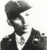
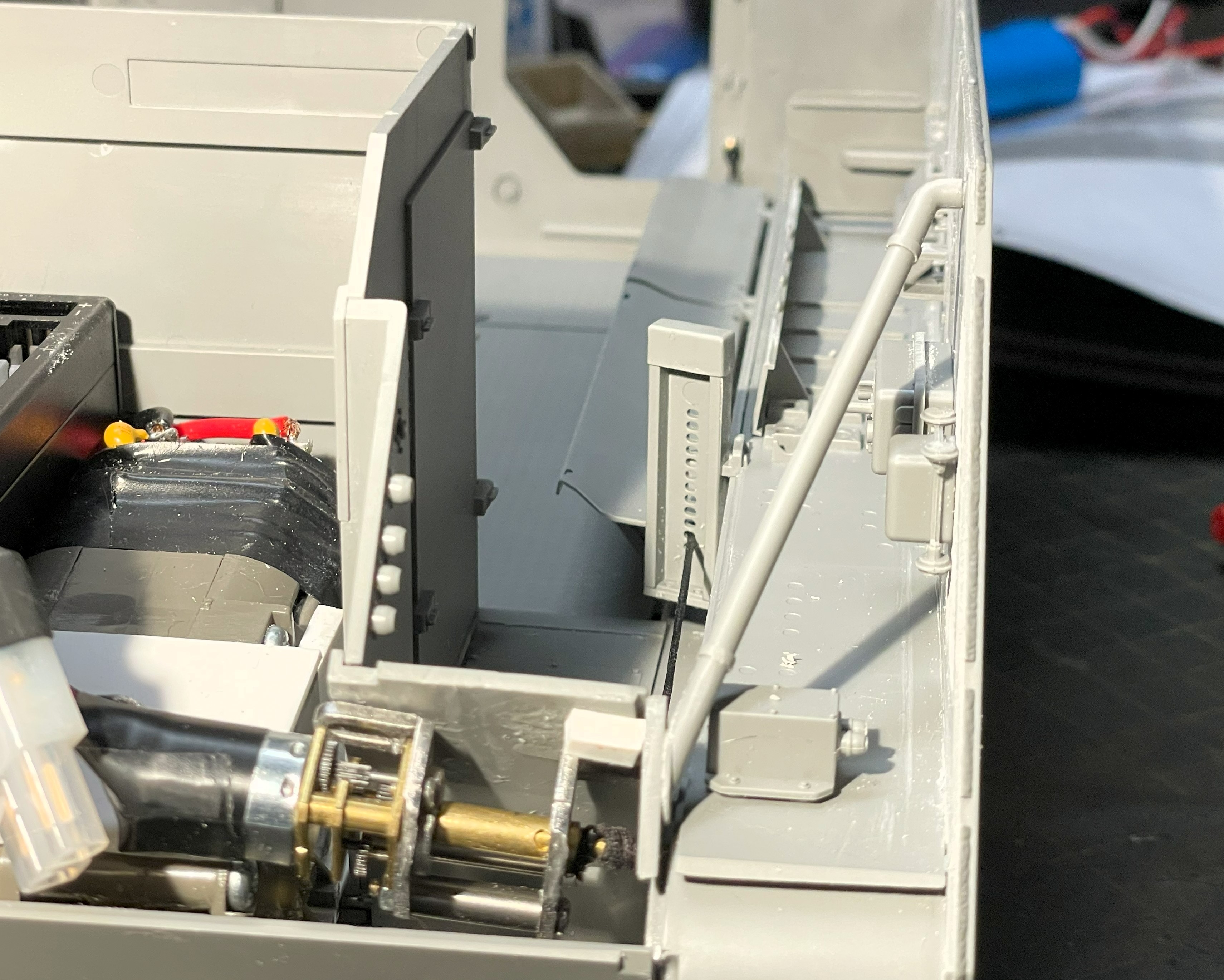
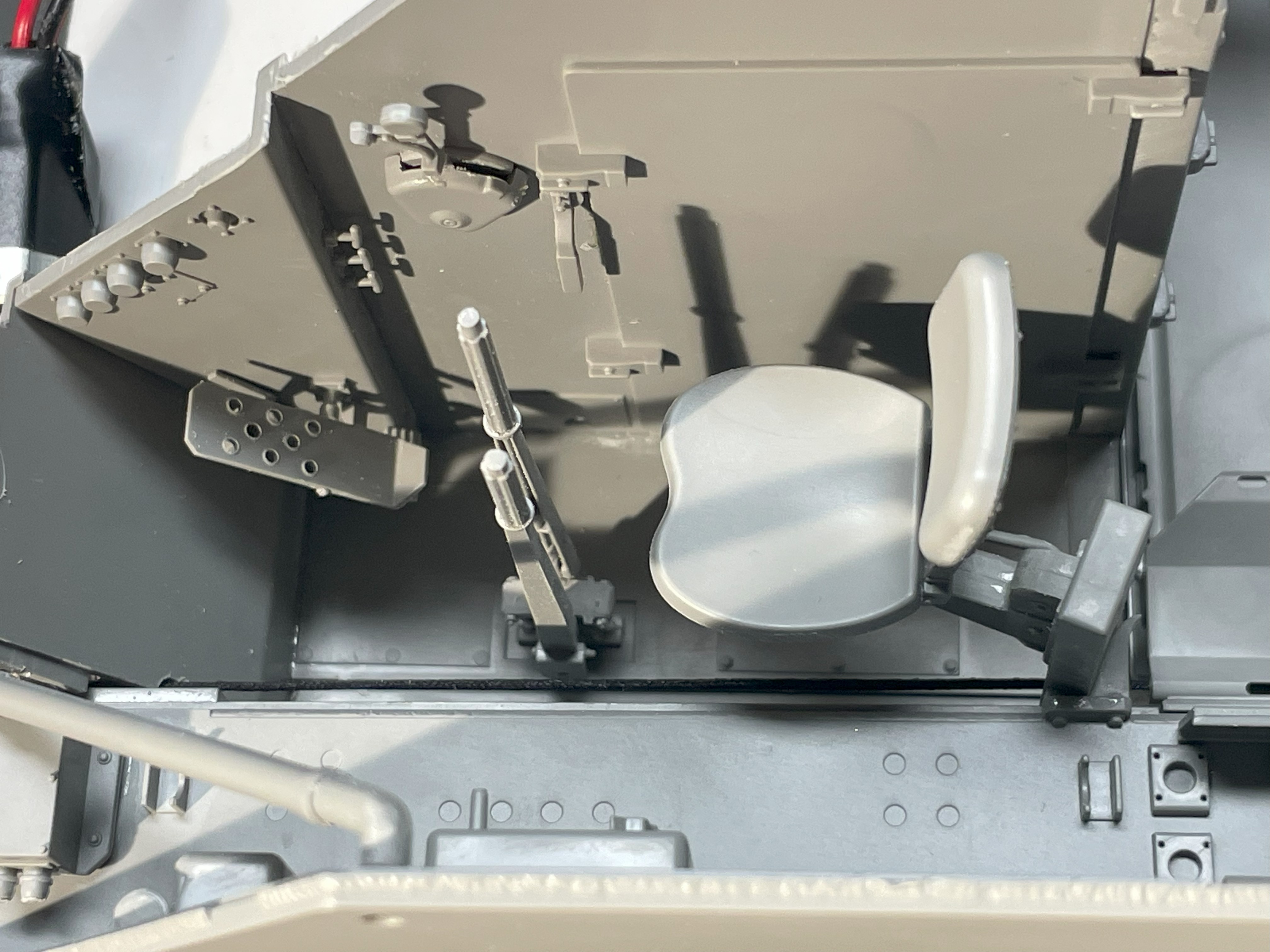
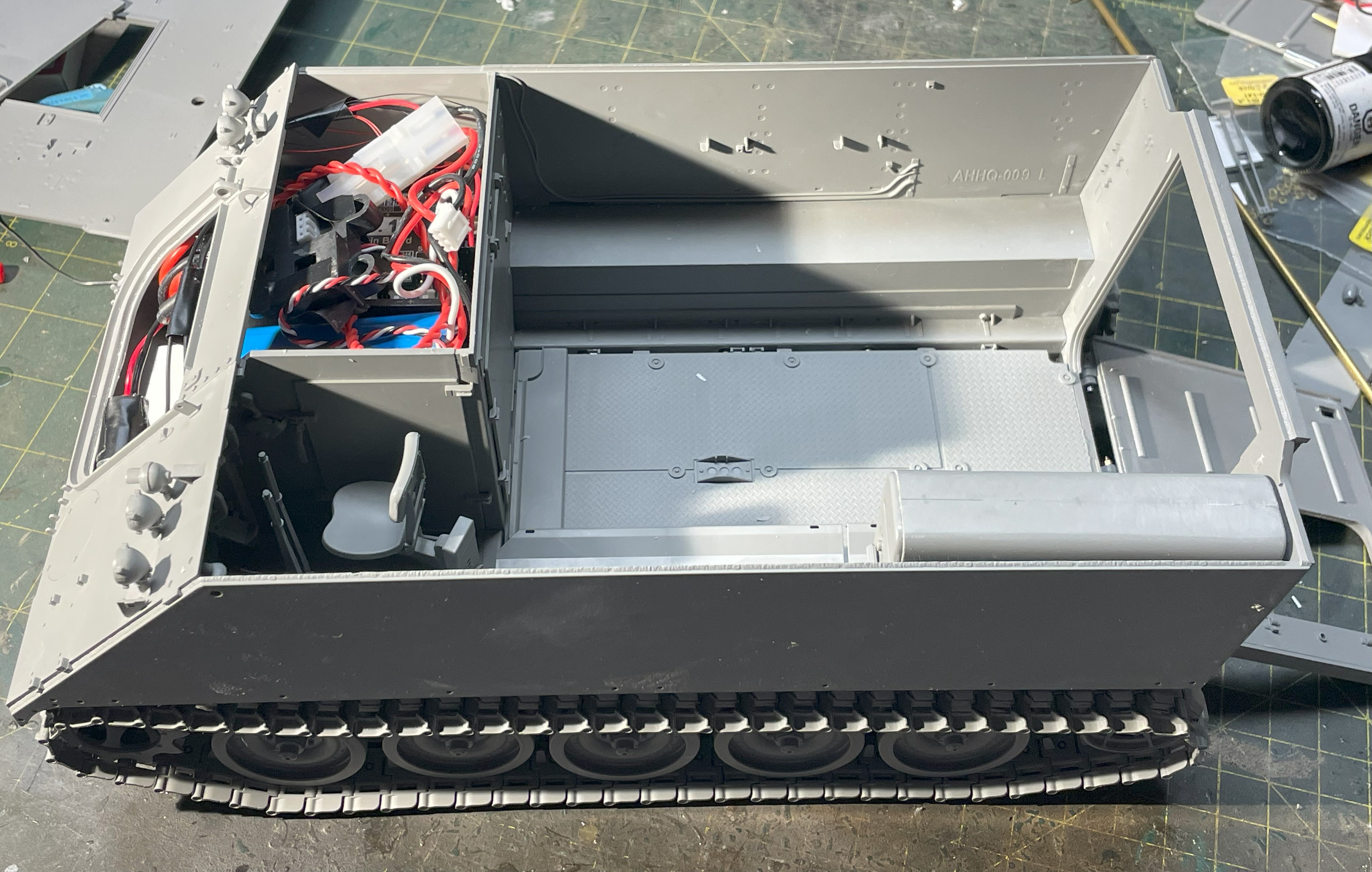
For the installation of the driver's seat mount, the cable for the rear ramp is in the way. My solution was to make the cable go through one of the seat height adjustment hole, second from the bottom.
- 1/16 RC M-113A1 ACAV - Converting the Takom/Andy's HHQ kit to RC
- 1.jpg (1.45 MiB) Viewed 1199 times
It works well, the cable is well hidden and protected. The horizontal seat bracket is just inserted without gluing. As i have ordered all 4 Jason Studio M113 resin 1/16 figures for this build, i want to know exactly the height of the driver's figure with his head coming out of the hatch before i determine the height of the seat, i prefer not to assume that the seat should be at the highest position.
- 1/16 RC M-113A1 ACAV - Converting the Takom/Andy's HHQ kit to RC
- 2.jpg (1.48 MiB) Viewed 1199 times
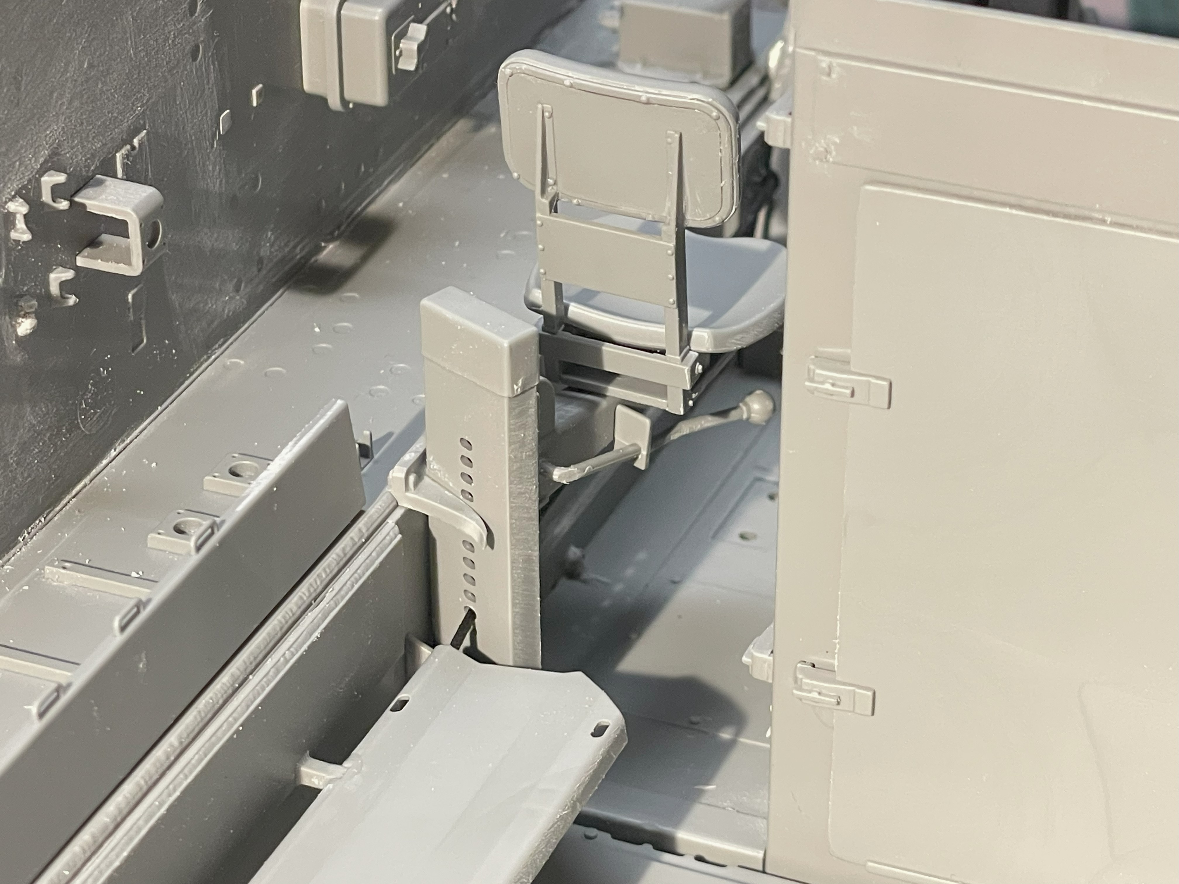
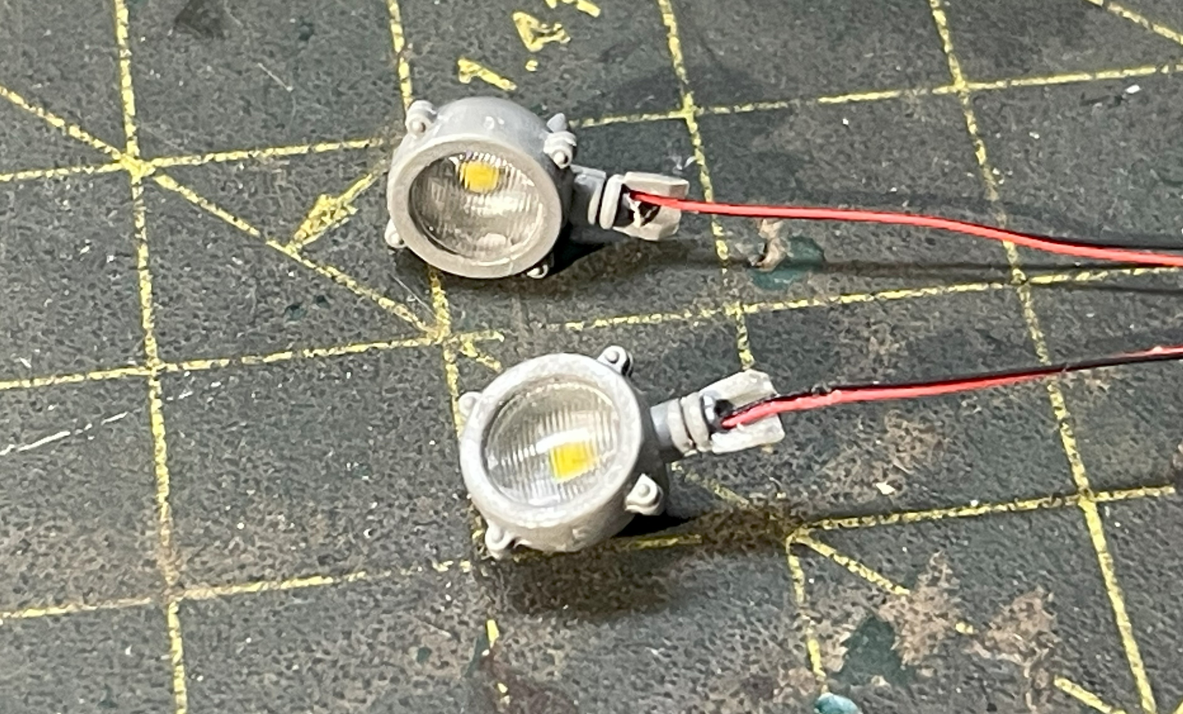
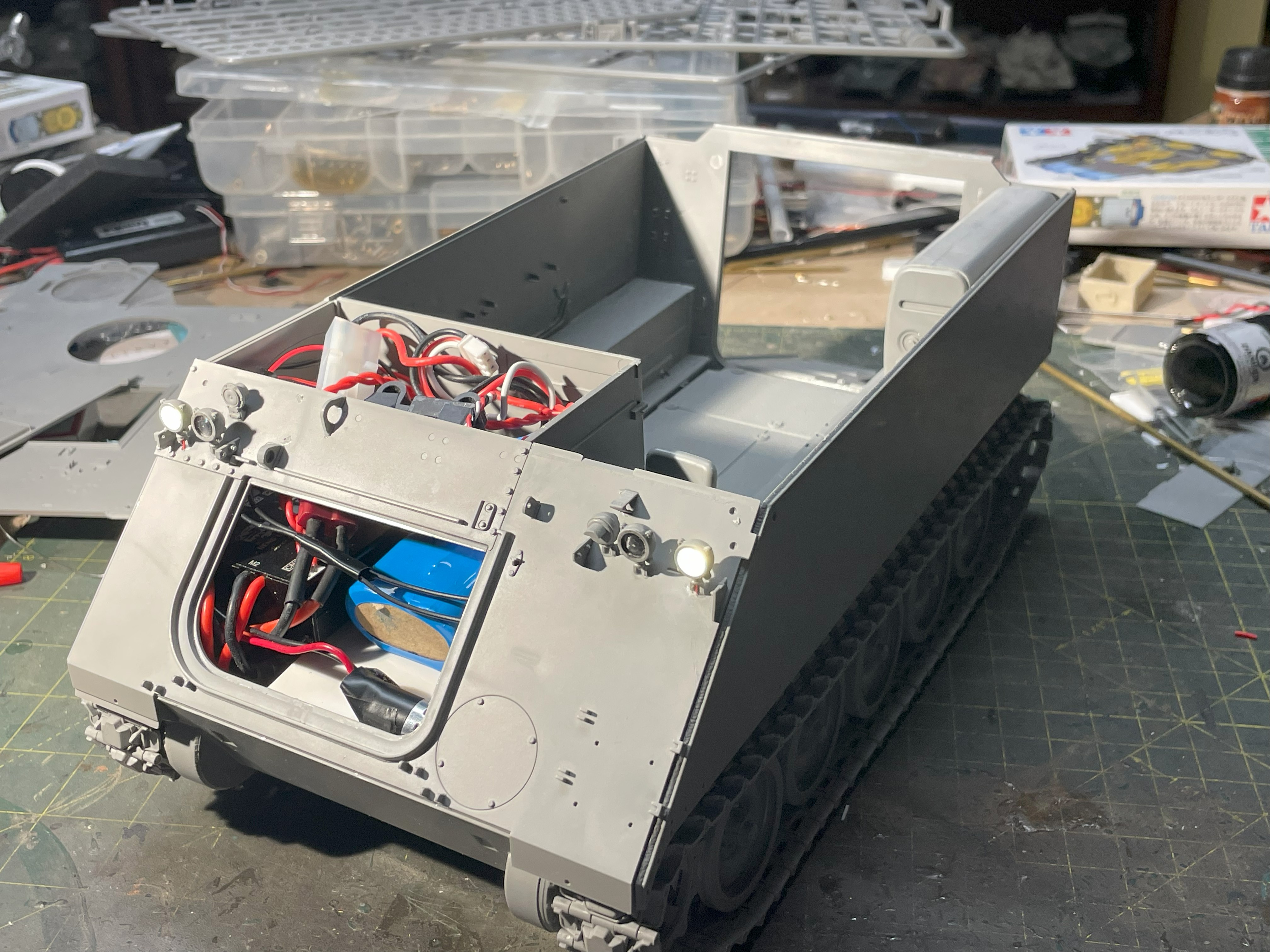
For the headlights, the model needs 2 working white headlights, the other 2 in the inside position are infra red and should be black.
- 1/16 RC M-113A1 ACAV - Converting the Takom/Andy's HHQ kit to RC
- 3.jpg (2.72 MiB) Viewed 1199 times
The kit's headlights are hollow, which is great. It is easy to drill a small hole in the mount and insert a Warm White LED that can be found on eBay, 20 for 9 dollars with free shipping. I have been advised in the past that my headlights were too bright. I finally found warm white colored LEDs that are definitely better.
It is very difficult to glue these LEDs in place. They are completely impervious to superglue. After giving it a small base at the bottom of the casing, I had to insert a tiny strip of plasticard in the wire's hole to squeeze the LED wire and make it stay in place until the glue is completely dry.

- 1/16 RC M-113A1 ACAV - Converting the Takom/Andy's HHQ kit to RC
- 4.jpg (2.05 MiB) Viewed 1199 times
After painting the interior in silver and tested them, i have enclosed the headlight.
- 1/16 RC M-113A1 ACAV - Converting the Takom/Andy's HHQ kit to RC
- 5.jpg (1.31 MiB) Viewed 1199 times
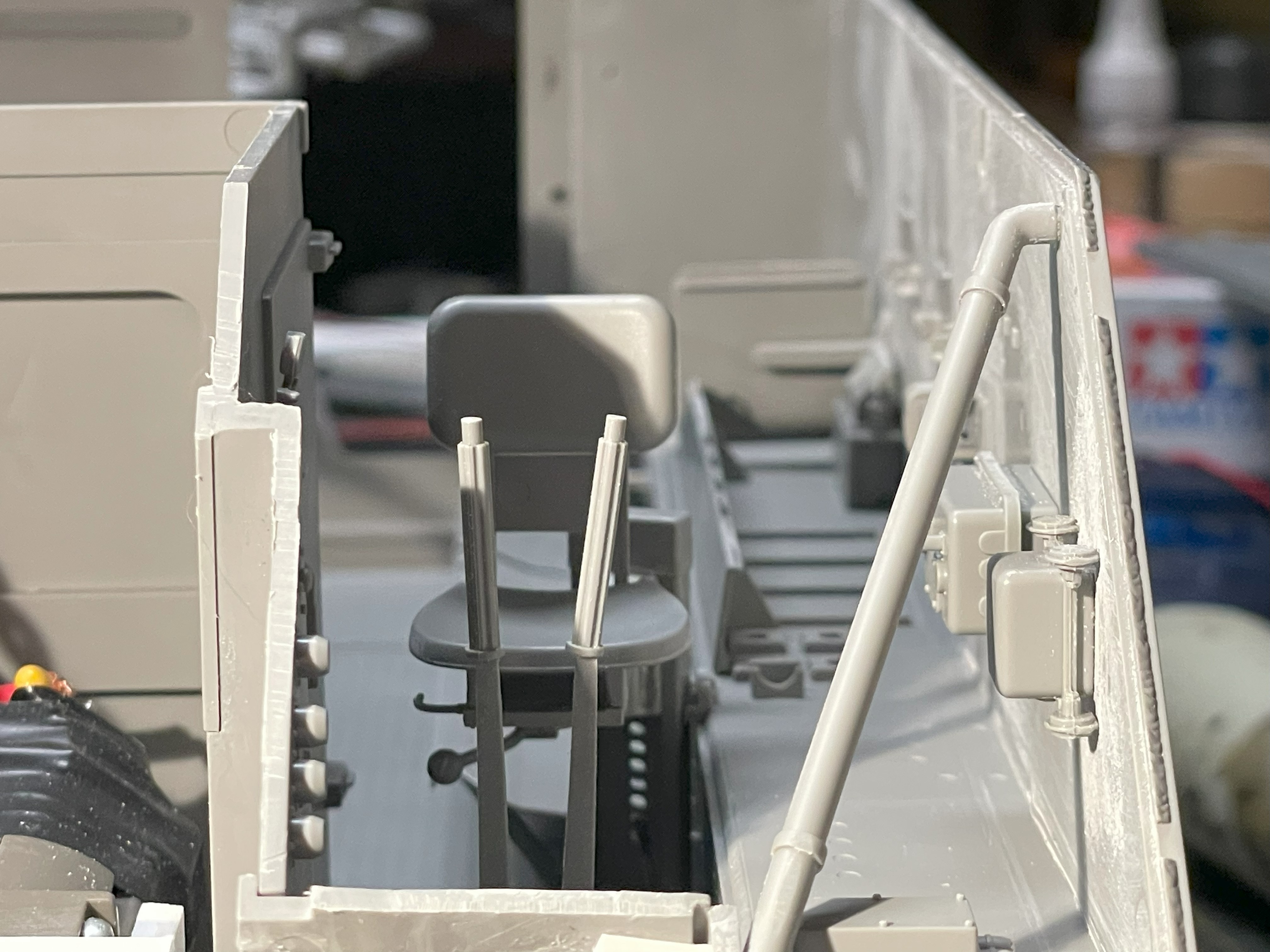
I have completed the area of the driver's position that i wanted to do at this stage. It is well detailed.
- 1/16 RC M-113A1 ACAV - Converting the Takom/Andy's HHQ kit to RC
- 6.jpg (1.44 MiB) Viewed 1199 times
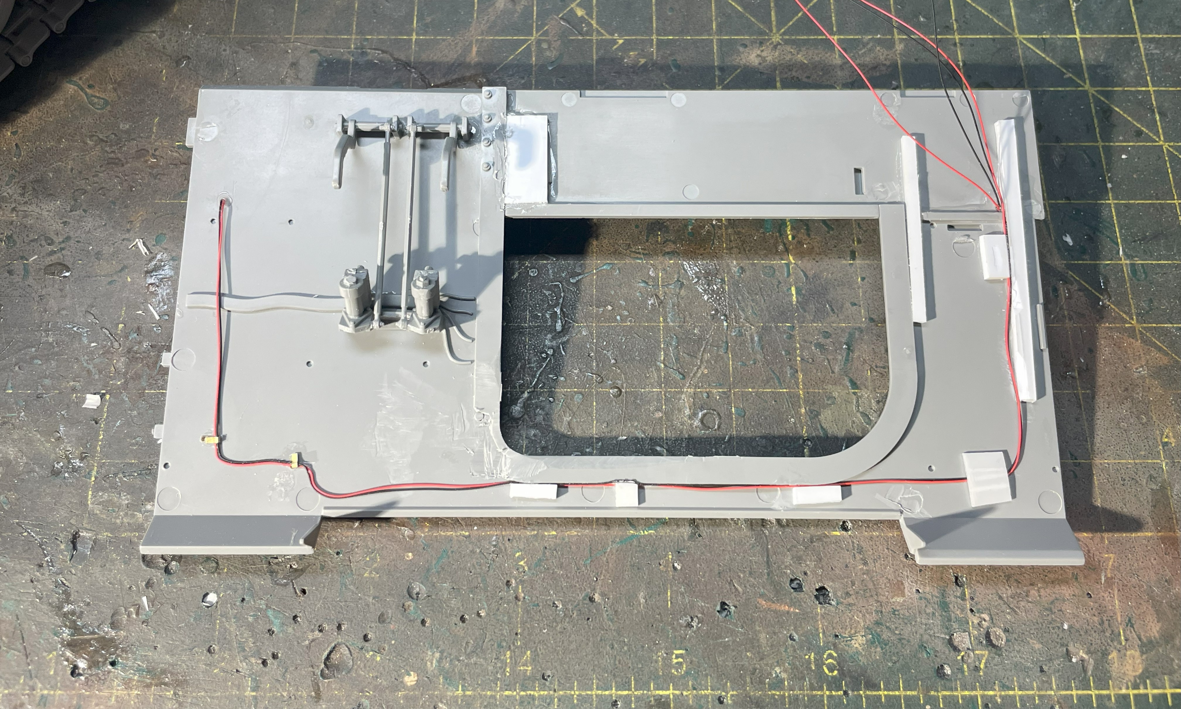
Those 4 pods on the left are for cables going into the engine compartment. I decided to make the speaker wires go through them.
- 1/16 RC M-113A1 ACAV - Converting the Takom/Andy's HHQ kit to RC
- 7.jpg (1.57 MiB) Viewed 1199 times
The headlights are installed and the wires are directed towards the engine compartment. The glacis is in two section, i added some reinforcement at the joints.
- 1/16 RC M-113A1 ACAV - Converting the Takom/Andy's HHQ kit to RC
- 8.jpg (2.05 MiB) Viewed 1199 times
The glacis is put in place with a few drops of superglue strategically placed. If i ever need to reopen the glacis because of some repair to the gearbox, winch or else, the glacis will snap out of position with some force applied at specific area. I tried to design something that would make the glacis easily removable but the part is very thin and it would be complicated because of the interior detailing.
- 1/16 RC M-113A1 ACAV - Converting the Takom/Andy's HHQ kit to RC
- 9.jpg (1.88 MiB) Viewed 1199 times
The headlights are working well, connected to LED4 port on the control board. I installed the electronics in the optimal position before closing the glacis, and i did a full electronic test. Well, "installed" is a big word, it more like piling them on top of each other, with the battery and the on/off switch at the top.
- 1/16 RC M-113A1 ACAV - Converting the Takom/Andy's HHQ kit to RC
- 10.jpg (1.74 MiB) Viewed 1199 times
Continuing on following post