1/16 RC M-113A1 ACAV - Converting the Takom/Andy's HHQ kit to RC

Re: 1/16 RC M-113A1 ACAV - Converting the Takom/Andy's HHQ kit to RC
For a static kit, that track and sprocket run really well. Terrific solutions as usual!
"Don't believe everything you see on the internet" - George S. Patton
Eric
Eric
-
Herr Dr. Professor
- Major
- Posts: 6133
- Joined: Mon Apr 22, 2019 10:48 pm
- Location: Southern Wisconsin USA
Re: 1/16 RC M-113A1 ACAV - Converting the Takom/Andy's HHQ kit to RC
Louis, you've done it again! What a demonstration of resourcefulness and skill--and the patience to get those tracks together and workable! WOO HOO!

Re: 1/16 RC M-113A1 ACAV - Converting the Takom/Andy's HHQ kit to RC
Thank you Dongskie, Ecam and Doc,
Got to admit that these plastic tracks, sprocket and gearbox are running well. It's rare to see this on a first attempt. I ran it for a few minutes, all good but the idler wheel needed a little adjustment to make it more loose. I have not build the other track yet for a full running test of the vehicle but i was able to let the vehicle loose and watch the behaviour of the track on the floor, moving the vehicle in a circular fashion. The tracks or gearbox are not struggling for a table top conversion, it might be different in the field, we'll see. There were no failures to report.
The trick is to keep everything light and simple, avoid over engineering or try to make this vehicle something that it is not.
- 1/16 RC M-113A1 ACAV - Converting the Takom/Andy's HHQ kit to RC
- IMG_6773.jpg (1.37 MiB) Viewed 1310 times
- 1/16 RC M-113A1 ACAV - Converting the Takom/Andy's HHQ kit to RC
- IMG_6762.jpg (849.84 KiB) Viewed 1310 times
Re: 1/16 RC M-113A1 ACAV - Converting the Takom/Andy's HHQ kit to RC
Hi everyone,
Here is the model in action.
Putting together the second track went much better than the first one, i was able to complete it in about 90 minutes. Everything goes better with experience. I ended up not losing any track links for its leaves me with a single spare link.
Track installed, it's time for a motorization test. I have rapidly stacked the electronics inside the engine compartment for the tests, pretty much as they would be later, except for the speaker that will be inside the fuel tank at the rear. The finalized placement and support for the electronics will be done later.
This is a shot from the video below, checking the working of the suspension.
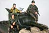
The vehicle is currently so light at the rear that some roadwheels do not feel any pressure to turn but that should change with the interior and some resin figures on the roof. Otherwise, i might have to put some weights under the floor.
The electronics will fit inside the engine compartment, allowing for the display of the complete interior detail of the rear crew compartment. The position for the rear ramp servo still need to be figured out.
Here is the model in action.
Regards, Louis
Here is the model in action.
Putting together the second track went much better than the first one, i was able to complete it in about 90 minutes. Everything goes better with experience. I ended up not losing any track links for its leaves me with a single spare link.
- 1/16 RC M-113A1 ACAV - Converting the Takom/Andy's HHQ kit to RC
- IMG_6785.jpg (2.44 MiB) Viewed 1293 times
Track installed, it's time for a motorization test. I have rapidly stacked the electronics inside the engine compartment for the tests, pretty much as they would be later, except for the speaker that will be inside the fuel tank at the rear. The finalized placement and support for the electronics will be done later.
- 1/16 RC M-113A1 ACAV - Converting the Takom/Andy's HHQ kit to RC
- IMG_6791.jpg (1.47 MiB) Viewed 1293 times
- 1/16 RC M-113A1 ACAV - Converting the Takom/Andy's HHQ kit to RC
- IMG_6792.jpg (1.09 MiB) Viewed 1293 times
This is a shot from the video below, checking the working of the suspension.
The vehicle is currently so light at the rear that some roadwheels do not feel any pressure to turn but that should change with the interior and some resin figures on the roof. Otherwise, i might have to put some weights under the floor.
- 1/16 RC M-113A1 ACAV - Converting the Takom/Andy's HHQ kit to RC
- Screenshot 2025-01-04 162009.png (1.39 MiB) Viewed 1293 times
The electronics will fit inside the engine compartment, allowing for the display of the complete interior detail of the rear crew compartment. The position for the rear ramp servo still need to be figured out.
- 1/16 RC M-113A1 ACAV - Converting the Takom/Andy's HHQ kit to RC
- Screenshot 2025-01-04 162341.png (853.69 KiB) Viewed 1293 times
Here is the model in action.
Regards, Louis
Re: 1/16 RC M-113A1 ACAV - Converting the Takom/Andy's HHQ kit to RC
Nice job! If the door opens by gravity, you may consider using a rope or fishing line to close. You will need to calculate the diameter of the pulley that will wrap the cable based on the movement you need. This system gives a lot of freedom when looking for the servo's location. It is good to set the servo speed realistically.
Re: 1/16 RC M-113A1 ACAV - Converting the Takom/Andy's HHQ kit to RC
Gravity and rope, that is an excellent idea. I had not thought about it. The rear ramp is lightly inclined so it could go down on its own if the hinges at the bottom are loose enough, exactly like the real thing actually. I could put some weight inside the ramp if required. Instead of a servo, I have one of those JJRC Winch designed for WPL trucks that i can use to pull and release its cable that would lower or raise the ramp. It's small enough. It would also provide a realistic movement, speed, and even sound.Almarza wrote: ↑Sun Jan 05, 2025 10:04 am Nice job! If the door opens by gravity, you may consider using a rope or fishing line to close. You will need to calculate the diameter of the pulley that will wrap the cable based on the movement you need. This system gives a lot of freedom when looking for the servo's location. It is good to set the servo speed realistically.
Takom provides the plastic part with a static pulley at the rear, it's really small. The winch could be at the front of the driver compartment, the cable could run under the floor, sticking out at the rear through the Takom part and pulley (tbd if static or working). The winch is powerful, the anchor on the ramp would need to be real solid.
I'll get on it before i hit the beach next week.
Thank you very much, Louis
- 1/16 RC M-113A1 ACAV - Converting the Takom/Andy's HHQ kit to RC
- Screenshot 2025-01-05 073821.png (599.03 KiB) Viewed 1232 times
- 1/16 RC M-113A1 ACAV - Converting the Takom/Andy's HHQ kit to RC
- Screenshot 2025-01-05 073843.png (561.04 KiB) Viewed 1232 times
- 1/16 RC M-113A1 ACAV - Converting the Takom/Andy's HHQ kit to RC
- Screenshot 2025-01-05 073937.png (376.23 KiB) Viewed 1232 times
- 1/16 RC M-113A1 ACAV - Converting the Takom/Andy's HHQ kit to RC
- IMG_6806.jpg (2.23 MiB) Viewed 1232 times
- 1/16 RC M-113A1 ACAV - Converting the Takom/Andy's HHQ kit to RC
- Screenshot 2025-01-05 081359.png (39.06 KiB) Viewed 1231 times
- 1/16 RC M-113A1 ACAV - Converting the Takom/Andy's HHQ kit to RC
- IMG_6807.jpg (844.96 KiB) Viewed 1232 times
Re: 1/16 RC M-113A1 ACAV - Converting the Takom/Andy's HHQ kit to RC
Hi everyone
The following 2 posts and video are for the operating rear ramp.
It was not easy but i managed to make it work.
This is the assembled JJRJ winch, i will call it version 1. The drum for the cable is quite big and the gearbox is running pretty fast. It needed to be modified. While doing some tests when plugged to CN3 (turret rotation port) on the TK 7.1, i determined it was running too fast even at the lowest speed. I almost discarded the option but decided to explore further as there are limited other options.
My first attempt was to make the cable run under the floor. At first, it was promising but i determined there were too much resistance on the cable. Going down to the floor, running thought torsion bars, then up at the rear and then a 90 degree towards the rear was too much. Although the winch had no issue pulling the cable to raise the ramp, it's everything else around it that was squeeking, bending and potentially cracking. Because the tread plate floor part needs to be glued to the bottom of the hull, any issue with the cable (breaking or otherwise) makes maintenance and repair impossible. I therefore selected to run the cable under the seats instead in order to keep things strait and simple.
The apparatus that holds the cable at the rear is quite light and needs to be protected.
I replaced the static pulley by a working one make of brass bolt, washers and tubing. This is the setup designed when the cable came up from under the floor. There was not enough room to do much else that give the hole an angle and avoid sharp corners. In a future M113 where i can design such solution from the start, i will relook at the "under the floor" option, but with a strait channel to the rear of the vehicle without obstacles, likely involving a small brass tube to protect the cable, and also look at different types of cables and pulleys available on the market.
On the ramp inner face, the plastic fins where the cable needs to be attached has to be replaced by a solid hook.
A Krupner brass hook was inserted at the same location. The hole needed to be enlarged a bit because of the thickness of the cable used.
A washer and epoxy glue was used under the ramp top plate to firmly attach the hook, spreading around the tension on the hook.
In order for the gravity to bring down the ramp on its own, it must have absolutely no resistance from the hinges. The fake bolts and plastic pins inside the hinges were replaced by very loose brass M1.4 bolts. If there is any friction in the hinge, the ramp won't come down on its own. You will release the cable and the ramp will stick in the upright position, trust me on that.
This is version 2 of the winch. Notice the smaller drum made in brass tube that makes the winch reel in the cable much slower, and that 2 of the 6 round beams holding the casing together have been cut. The winch would not fit the allocated space at the front without removing them. 4 out of 6 is solid enough for the purpose.
And this is V3 of the winch. After finding out that V2 was still reeling in the cable too fast, i made an extension with the smallest tube that could be technically used. This version was satisfactory. The brass tubes are epoxy glued to the main shaft. This mod was a last ditch effort, a one way ticket.
Continuing on following post
The following 2 posts and video are for the operating rear ramp.
It was not easy but i managed to make it work.
This is the assembled JJRJ winch, i will call it version 1. The drum for the cable is quite big and the gearbox is running pretty fast. It needed to be modified. While doing some tests when plugged to CN3 (turret rotation port) on the TK 7.1, i determined it was running too fast even at the lowest speed. I almost discarded the option but decided to explore further as there are limited other options.
- 1/16 RC M-113A1 ACAV - Converting the Takom/Andy's HHQ kit to RC
- 1.jpg (1.21 MiB) Viewed 1166 times
My first attempt was to make the cable run under the floor. At first, it was promising but i determined there were too much resistance on the cable. Going down to the floor, running thought torsion bars, then up at the rear and then a 90 degree towards the rear was too much. Although the winch had no issue pulling the cable to raise the ramp, it's everything else around it that was squeeking, bending and potentially cracking. Because the tread plate floor part needs to be glued to the bottom of the hull, any issue with the cable (breaking or otherwise) makes maintenance and repair impossible. I therefore selected to run the cable under the seats instead in order to keep things strait and simple.
- 1/16 RC M-113A1 ACAV - Converting the Takom/Andy's HHQ kit to RC
- 2.jpg (1.41 MiB) Viewed 1166 times
The apparatus that holds the cable at the rear is quite light and needs to be protected.
- 1/16 RC M-113A1 ACAV - Converting the Takom/Andy's HHQ kit to RC
- 4.jpg (1.48 MiB) Viewed 1166 times
I replaced the static pulley by a working one make of brass bolt, washers and tubing. This is the setup designed when the cable came up from under the floor. There was not enough room to do much else that give the hole an angle and avoid sharp corners. In a future M113 where i can design such solution from the start, i will relook at the "under the floor" option, but with a strait channel to the rear of the vehicle without obstacles, likely involving a small brass tube to protect the cable, and also look at different types of cables and pulleys available on the market.
- 1/16 RC M-113A1 ACAV - Converting the Takom/Andy's HHQ kit to RC
- 3a.jpg (1.17 MiB) Viewed 1166 times
On the ramp inner face, the plastic fins where the cable needs to be attached has to be replaced by a solid hook.
- 1/16 RC M-113A1 ACAV - Converting the Takom/Andy's HHQ kit to RC
- 5.jpg (1.79 MiB) Viewed 1166 times
A Krupner brass hook was inserted at the same location. The hole needed to be enlarged a bit because of the thickness of the cable used.
- 1/16 RC M-113A1 ACAV - Converting the Takom/Andy's HHQ kit to RC
- 6.jpg (2.24 MiB) Viewed 1166 times
A washer and epoxy glue was used under the ramp top plate to firmly attach the hook, spreading around the tension on the hook.
- 1/16 RC M-113A1 ACAV - Converting the Takom/Andy's HHQ kit to RC
- 7.jpg (1.08 MiB) Viewed 1166 times
In order for the gravity to bring down the ramp on its own, it must have absolutely no resistance from the hinges. The fake bolts and plastic pins inside the hinges were replaced by very loose brass M1.4 bolts. If there is any friction in the hinge, the ramp won't come down on its own. You will release the cable and the ramp will stick in the upright position, trust me on that.
- 1/16 RC M-113A1 ACAV - Converting the Takom/Andy's HHQ kit to RC
- 8.jpg (892.96 KiB) Viewed 1166 times
This is version 2 of the winch. Notice the smaller drum made in brass tube that makes the winch reel in the cable much slower, and that 2 of the 6 round beams holding the casing together have been cut. The winch would not fit the allocated space at the front without removing them. 4 out of 6 is solid enough for the purpose.
- 1/16 RC M-113A1 ACAV - Converting the Takom/Andy's HHQ kit to RC
- 9.jpg (1.57 MiB) Viewed 1166 times
And this is V3 of the winch. After finding out that V2 was still reeling in the cable too fast, i made an extension with the smallest tube that could be technically used. This version was satisfactory. The brass tubes are epoxy glued to the main shaft. This mod was a last ditch effort, a one way ticket.
- 1/16 RC M-113A1 ACAV - Converting the Takom/Andy's HHQ kit to RC
- 10.jpg (1.24 MiB) Viewed 1166 times
Continuing on following post
Last edited by lmcq11 on Tue Jan 07, 2025 1:27 pm, edited 9 times in total.

Re: 1/16 RC M-113A1 ACAV - Converting the Takom/Andy's HHQ kit to RC
Space is extremely limited at the front of the driver's position. The design faced a lot of restrictions. A hole is made on the side to hold on to the extremity of the winch drum.
Not pretty but this is the only way i could fit the winch inside the available space, always checking with the glacis part to ensure it will be close correctly on top of it all. I sealed the top area of the gearbox with a plasticard plate and a few drops of superglue to prevent electrical wires from touching and damaging the gears. Inner beauty of the inside of the engine compartment is not the scope of this project...
Once i have done more tests, the winch will be permanently locked in place. For now, it is holding on with superglue, which was a good way to try different ways to position the winch. I must have snapped it out of position 10 times for winch redesign or repositioning.
Checking that the glacis still fits correctly.
Every half millimeter counts on such build. It is better not to assume anything and dry fit everything all the time.
Views of the situation at the ramp. The left side seats were installed to check the behaviour of the cable running under them. The Takom ramp is made of two halves and is hollow inside. I glued 3 large metal washers inside the ramp at the top to give it some extra weight and it helps the ramp go down with gravity. It makes a difference but it’s important to have the right balance. If too much weight is added. It will create some problem somewhere along the line when raising the ramp.
The cable is now running under the seat. It really does not show much and is almost strait front the front to the rear.
The floor is an area of the kit where the fit is difficult, it takes times and a lot of adjustments to make the tread plate part fall into place. I never managed to make the floor stay completely flat on the bottom of the hull without gluing it. Even glue had problems making the floor stick in place.
A notch was made on the front plate to help position the cable.
And finally, here is the M113 ramp in action. As the winch is connected to the CN3 turret rotation port, it has speed control and a realistic gear sound. Needs some plactice to control the ramp at the lowest possible speed. I am happy with the results. However, the winch needs to be operated carefully because it is very powerful and could tear apart the ramp or the driver’s compartment if you don’t stop it. I thought about using a servo instead of the winch but I determined that a servo linked to the TK 7.1 barrel elevation port does not have enough range to pull the wire without some kind of gizmo added to the servo arm to extend the range. Another control board with a free servo channel could provide more options but the space for a servo is equally restricted at the front, unless it is made apparent next to the driver.
This is the model as it stands today. Now that the complicated part of the build is done, i can relax. The rest of the build will be mostly assembling the plastic kit, plus setting up a few LEDs. What was taking me days to scratch build elements on previous M113 builds is now done in minutes. This kit is great and the level of detail is amazing. The RC features makes it come alive.
Regards, Louis
- 1/16 RC M-113A1 ACAV - Converting the Takom/Andy's HHQ kit to RC
- 11.jpg (1.25 MiB) Viewed 1161 times
Not pretty but this is the only way i could fit the winch inside the available space, always checking with the glacis part to ensure it will be close correctly on top of it all. I sealed the top area of the gearbox with a plasticard plate and a few drops of superglue to prevent electrical wires from touching and damaging the gears. Inner beauty of the inside of the engine compartment is not the scope of this project...
- 1/16 RC M-113A1 ACAV - Converting the Takom/Andy's HHQ kit to RC
- 12.jpg (1.44 MiB) Viewed 1161 times
Once i have done more tests, the winch will be permanently locked in place. For now, it is holding on with superglue, which was a good way to try different ways to position the winch. I must have snapped it out of position 10 times for winch redesign or repositioning.
- 1/16 RC M-113A1 ACAV - Converting the Takom/Andy's HHQ kit to RC
- 13.jpg (1.34 MiB) Viewed 1161 times
Checking that the glacis still fits correctly.
- 1/16 RC M-113A1 ACAV - Converting the Takom/Andy's HHQ kit to RC
- 14.jpg (2.03 MiB) Viewed 1161 times
Every half millimeter counts on such build. It is better not to assume anything and dry fit everything all the time.
- 1/16 RC M-113A1 ACAV - Converting the Takom/Andy's HHQ kit to RC
- 15.jpg (655.6 KiB) Viewed 1161 times
Views of the situation at the ramp. The left side seats were installed to check the behaviour of the cable running under them. The Takom ramp is made of two halves and is hollow inside. I glued 3 large metal washers inside the ramp at the top to give it some extra weight and it helps the ramp go down with gravity. It makes a difference but it’s important to have the right balance. If too much weight is added. It will create some problem somewhere along the line when raising the ramp.
- 1/16 RC M-113A1 ACAV - Converting the Takom/Andy's HHQ kit to RC
- 16.jpg (1.54 MiB) Viewed 1161 times
The cable is now running under the seat. It really does not show much and is almost strait front the front to the rear.
- 1/16 RC M-113A1 ACAV - Converting the Takom/Andy's HHQ kit to RC
- 17.jpg (1.62 MiB) Viewed 1161 times
The floor is an area of the kit where the fit is difficult, it takes times and a lot of adjustments to make the tread plate part fall into place. I never managed to make the floor stay completely flat on the bottom of the hull without gluing it. Even glue had problems making the floor stick in place.
- 1/16 RC M-113A1 ACAV - Converting the Takom/Andy's HHQ kit to RC
- 18.jpg (1.8 MiB) Viewed 1161 times
A notch was made on the front plate to help position the cable.
- 1/16 RC M-113A1 ACAV - Converting the Takom/Andy's HHQ kit to RC
- 20.jpg (1.45 MiB) Viewed 1161 times
And finally, here is the M113 ramp in action. As the winch is connected to the CN3 turret rotation port, it has speed control and a realistic gear sound. Needs some plactice to control the ramp at the lowest possible speed. I am happy with the results. However, the winch needs to be operated carefully because it is very powerful and could tear apart the ramp or the driver’s compartment if you don’t stop it. I thought about using a servo instead of the winch but I determined that a servo linked to the TK 7.1 barrel elevation port does not have enough range to pull the wire without some kind of gizmo added to the servo arm to extend the range. Another control board with a free servo channel could provide more options but the space for a servo is equally restricted at the front, unless it is made apparent next to the driver.
This is the model as it stands today. Now that the complicated part of the build is done, i can relax. The rest of the build will be mostly assembling the plastic kit, plus setting up a few LEDs. What was taking me days to scratch build elements on previous M113 builds is now done in minutes. This kit is great and the level of detail is amazing. The RC features makes it come alive.
- 1/16 RC M-113A1 ACAV - Converting the Takom/Andy's HHQ kit to RC
- 21.jpg (1.64 MiB) Viewed 1161 times
Regards, Louis
Re: 1/16 RC M-113A1 ACAV - Converting the Takom/Andy's HHQ kit to RC
Hi everyone,
Back from beach vacation, i had a great time.
This post is for the speaker. I want to free up some space in the engine compartment and also add some weight at the rear of the vehicle so i will be installing the speaker inside the fuel tank.
As mentioned before, in my opinion, Takom made a design error. These molded on wiring on the wall part should have been provided as flexible rubber wire with detailed instructions on how to install them. These hard plastic lines on the armor will also be extremely hard to paint properly. Except for the hand brush virtuoso, there will be all kind of bleeding along the wires at the joints. And those cables are not really round.
As i need to run my own wires along the walls for the speaker and also for interior lights, these molded on wires are creating a lot of issues.
As seen in reference pictures, there is a lot more wiring, and most of it is twisting and turning in all directions away from the walls, not flat on the walls. Most should be painted black. There are important anchor points as well that were not represented.
So, i took some time to remove all the molded on wiring with a blade, then with nail files of various grain. After a primer is sprayed, a fine tuning sanding will be done for a smooth finish. If i had known i would be doing this, the task of removing the molded on wiring would have been done before assembling the hull parts.
A Heng Long speaker will be used. It fits inside the fuel tank.
Just need to remove the back cover.
The M113 fuel tank is not positioned flat on the armor wall. There is some spacing in between. So, i drilled a few holes on the back of the fuel tank for the sound to come out. These do not show. I also rounded the edges of the speaker's cover to fit inside the rounded edges of the back plate of the fuel tank. It is then glued in place. The black and red wires are replaced by longer black wire that will not require painting. This is a major benefit of replacing the molded on wires. It will also look a lot more realistic.
The speaker is glued inside the back plate of the fuel tank, facing the back and the holes for the sound to come out. Before sealing the fuel tank, tests are made to ensure everything works well.
And here we have an M113 fuel tank with speaker inside, and with black wires that will not require painting. Some fragile details have been left out at this time. The fuel tank will be completed with all its exterior detailing before painting. A wire junction box is seen next to the fuel tank so it made sense for the speaker wires to go though it. Holes were drilled and the part was inserted.
As seen in reference picture, this junction box has wiring attached and seem to come out from behind the fuel tank at the top.
Continuing on following post
Back from beach vacation, i had a great time.
This post is for the speaker. I want to free up some space in the engine compartment and also add some weight at the rear of the vehicle so i will be installing the speaker inside the fuel tank.
As mentioned before, in my opinion, Takom made a design error. These molded on wiring on the wall part should have been provided as flexible rubber wire with detailed instructions on how to install them. These hard plastic lines on the armor will also be extremely hard to paint properly. Except for the hand brush virtuoso, there will be all kind of bleeding along the wires at the joints. And those cables are not really round.
As i need to run my own wires along the walls for the speaker and also for interior lights, these molded on wires are creating a lot of issues.
- 1/16 RC M-113A1 ACAV - Converting the Takom/Andy's HHQ kit to RC
- 0.jpg (1.15 MiB) Viewed 920 times
As seen in reference pictures, there is a lot more wiring, and most of it is twisting and turning in all directions away from the walls, not flat on the walls. Most should be painted black. There are important anchor points as well that were not represented.
- 1/16 RC M-113A1 ACAV - Converting the Takom/Andy's HHQ kit to RC
- 0a.png (1.03 MiB) Viewed 920 times
- 1/16 RC M-113A1 ACAV - Converting the Takom/Andy's HHQ kit to RC
- 0b.png (1.08 MiB) Viewed 920 times
So, i took some time to remove all the molded on wiring with a blade, then with nail files of various grain. After a primer is sprayed, a fine tuning sanding will be done for a smooth finish. If i had known i would be doing this, the task of removing the molded on wiring would have been done before assembling the hull parts.
- 1/16 RC M-113A1 ACAV - Converting the Takom/Andy's HHQ kit to RC
- 0f.jpg (1.68 MiB) Viewed 920 times
A Heng Long speaker will be used. It fits inside the fuel tank.
- 1/16 RC M-113A1 ACAV - Converting the Takom/Andy's HHQ kit to RC
- 1.jpg (996.18 KiB) Viewed 920 times
Just need to remove the back cover.
- 1/16 RC M-113A1 ACAV - Converting the Takom/Andy's HHQ kit to RC
- 2.jpg (1.72 MiB) Viewed 920 times
The M113 fuel tank is not positioned flat on the armor wall. There is some spacing in between. So, i drilled a few holes on the back of the fuel tank for the sound to come out. These do not show. I also rounded the edges of the speaker's cover to fit inside the rounded edges of the back plate of the fuel tank. It is then glued in place. The black and red wires are replaced by longer black wire that will not require painting. This is a major benefit of replacing the molded on wires. It will also look a lot more realistic.
- 1/16 RC M-113A1 ACAV - Converting the Takom/Andy's HHQ kit to RC
- 3.jpg (1.98 MiB) Viewed 920 times
The speaker is glued inside the back plate of the fuel tank, facing the back and the holes for the sound to come out. Before sealing the fuel tank, tests are made to ensure everything works well.
- 1/16 RC M-113A1 ACAV - Converting the Takom/Andy's HHQ kit to RC
- 4.jpg (2.19 MiB) Viewed 920 times
And here we have an M113 fuel tank with speaker inside, and with black wires that will not require painting. Some fragile details have been left out at this time. The fuel tank will be completed with all its exterior detailing before painting. A wire junction box is seen next to the fuel tank so it made sense for the speaker wires to go though it. Holes were drilled and the part was inserted.
- 1/16 RC M-113A1 ACAV - Converting the Takom/Andy's HHQ kit to RC
- 5.jpg (1.59 MiB) Viewed 920 times
As seen in reference picture, this junction box has wiring attached and seem to come out from behind the fuel tank at the top.
- 1/16 RC M-113A1 ACAV - Converting the Takom/Andy's HHQ kit to RC
- 5a.png (789.32 KiB) Viewed 920 times
Continuing on following post
Last edited by lmcq11 on Fri Jan 24, 2025 8:21 pm, edited 3 times in total.
