Hi,
The following posts are for the smoke grenade dischargers.
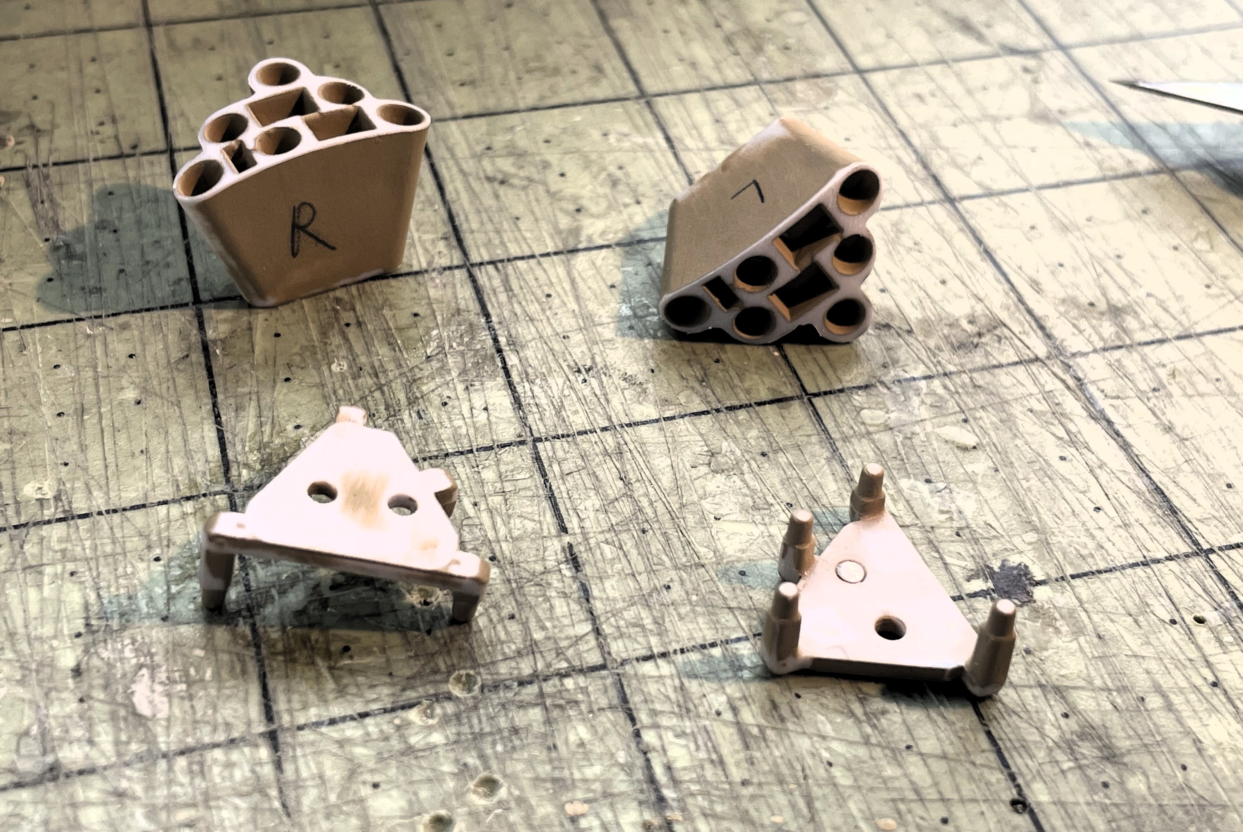
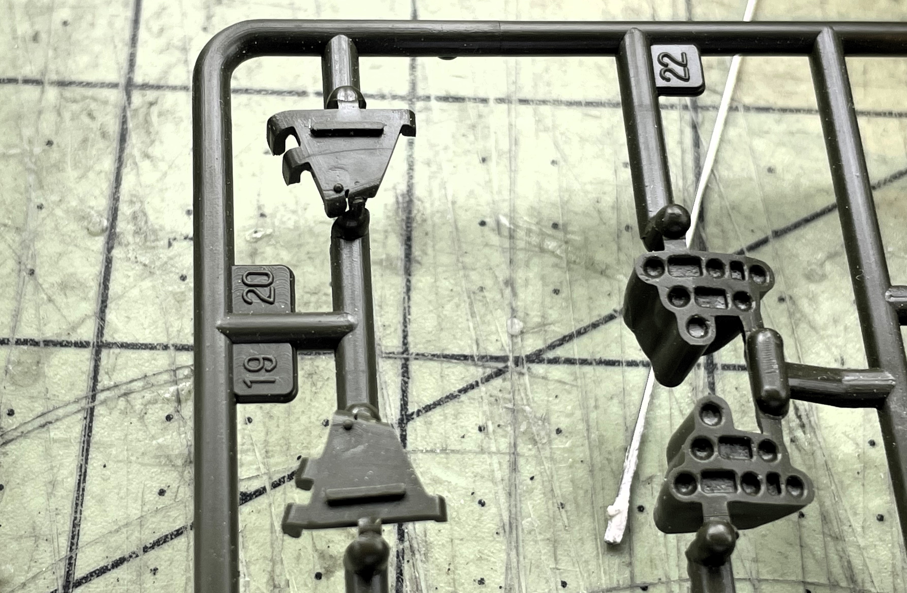
These are the parts coming with the TONGDE model. The main part looks similar to the Heng Long Abrams. The base part has a limited resemblance to the required mounts of the M60, and is actually inverted and is way too low. Complicating things is the fact that the parts are different between left and right and must not be mixed at any time during the build.
- 1/16 RC USMC M-60A1 US tank with ERA - Build
- IMG_1135.JPG (1.96 MiB) Viewed 1132 times
Looking at the 1/35 Academy M-60A1 Rise kit for information to help me out, there is not much there either. It is similar to the TONGDE model and also wrong.
- 1/16 RC USMC M-60A1 US tank with ERA - Build
- IMG_1136.JPG (1.33 MiB) Viewed 1132 times
Looks like i have to rely entirely on the Sabot/Verlinden photo book on the M-60A1 and eyeball some specs. I am fortunate to have this book because i would otherwise not have any information other than some vague pictures from far away.
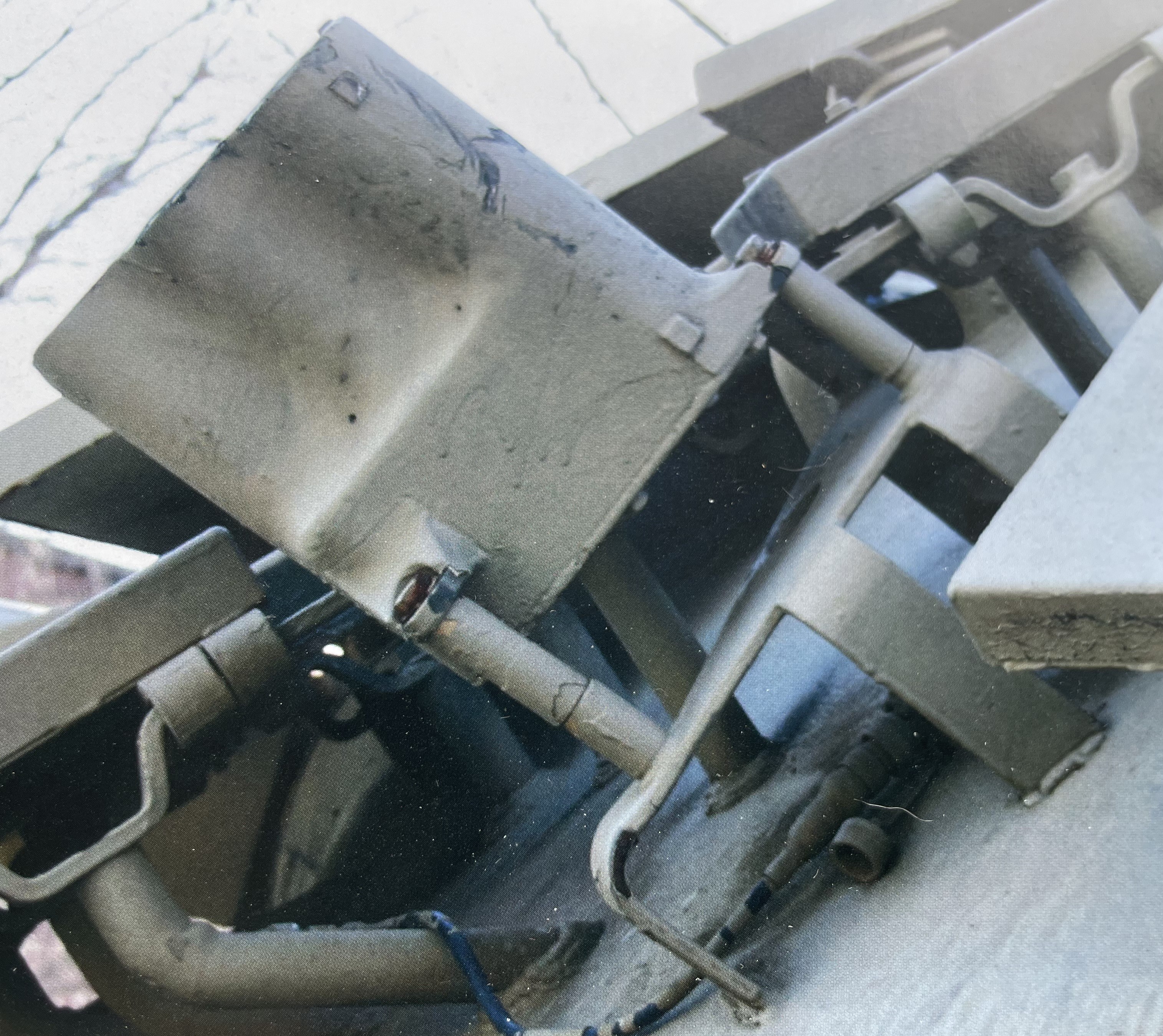
We can see the shape of the grenade discharger sides (different here), the intricate mount and especially the extensions pipes with the base that must have been installed because of the spaced ERA blocks. The dischargers are much higher than the parts provided.
This sight is enough to discourage the most hardened modeller. It is highly visible. On my model, which is a scale and RC model, it would need to be accurate and solid. I studied this picture for quite a while, I determined the best way to build this is to do exactly the same thing... No way around it. DKLM will likely one day create a detail set from their 3D printed turret, if not a complete turret replacement but it would be expensive and not much would be left of the original Tongde model. It would also still require mods for the M-60a1 with ERA.
- 1/16 RC USMC M-60A1 US tank with ERA - Build
- IMG_1151.JPG (2.45 MiB) Viewed 1132 times
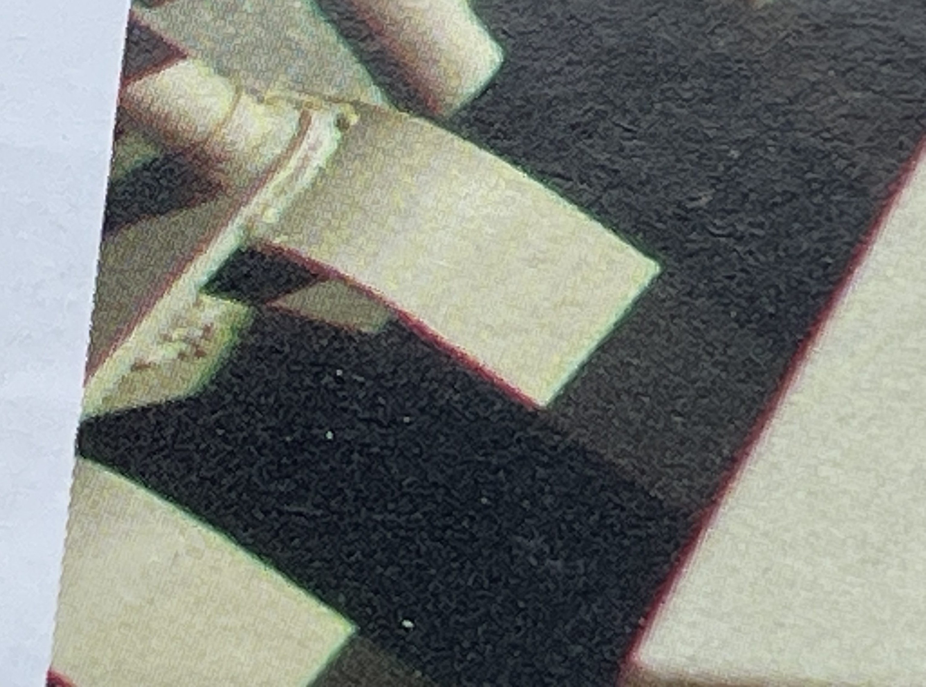
Another clearer picture show that the base is actually made of soldered metal plates. Ok, I can do that and it would be solid.
- 1/16 RC USMC M-60A1 US tank with ERA - Build
- IMG_1152.JPG (781.03 KiB) Viewed 1132 times
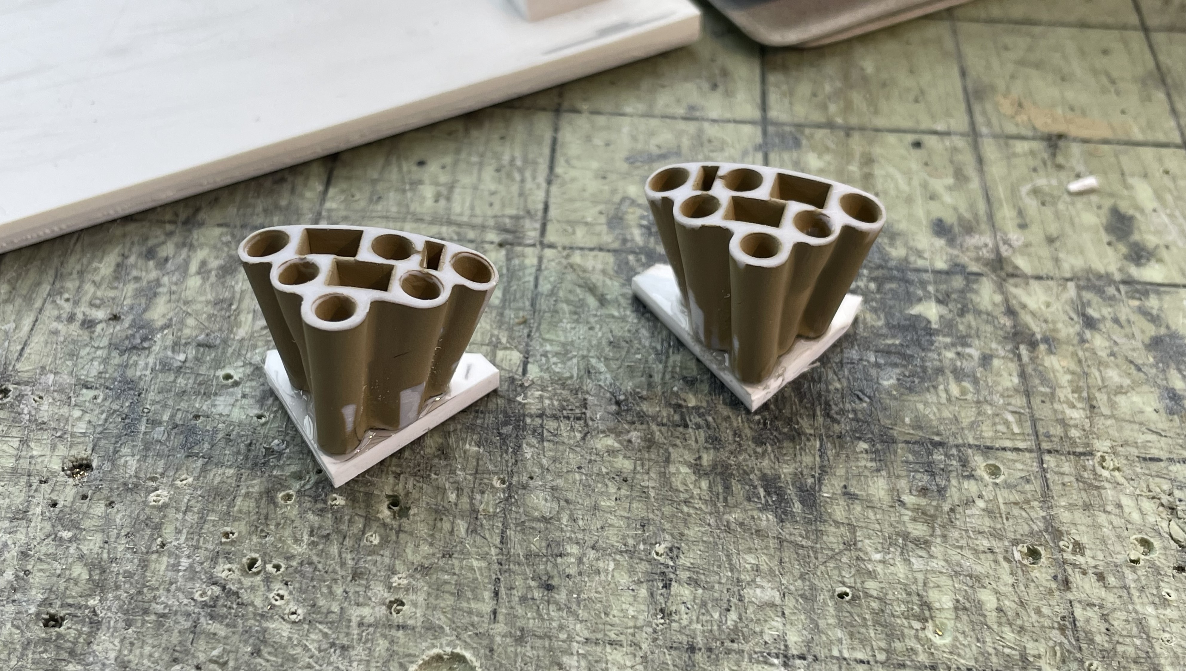
I extended the dischargers a bit with a bottom plate as they seemed short.
- 1/16 RC USMC M-60A1 US tank with ERA - Build
- IMG_1150.JPG (1.63 MiB) Viewed 1132 times
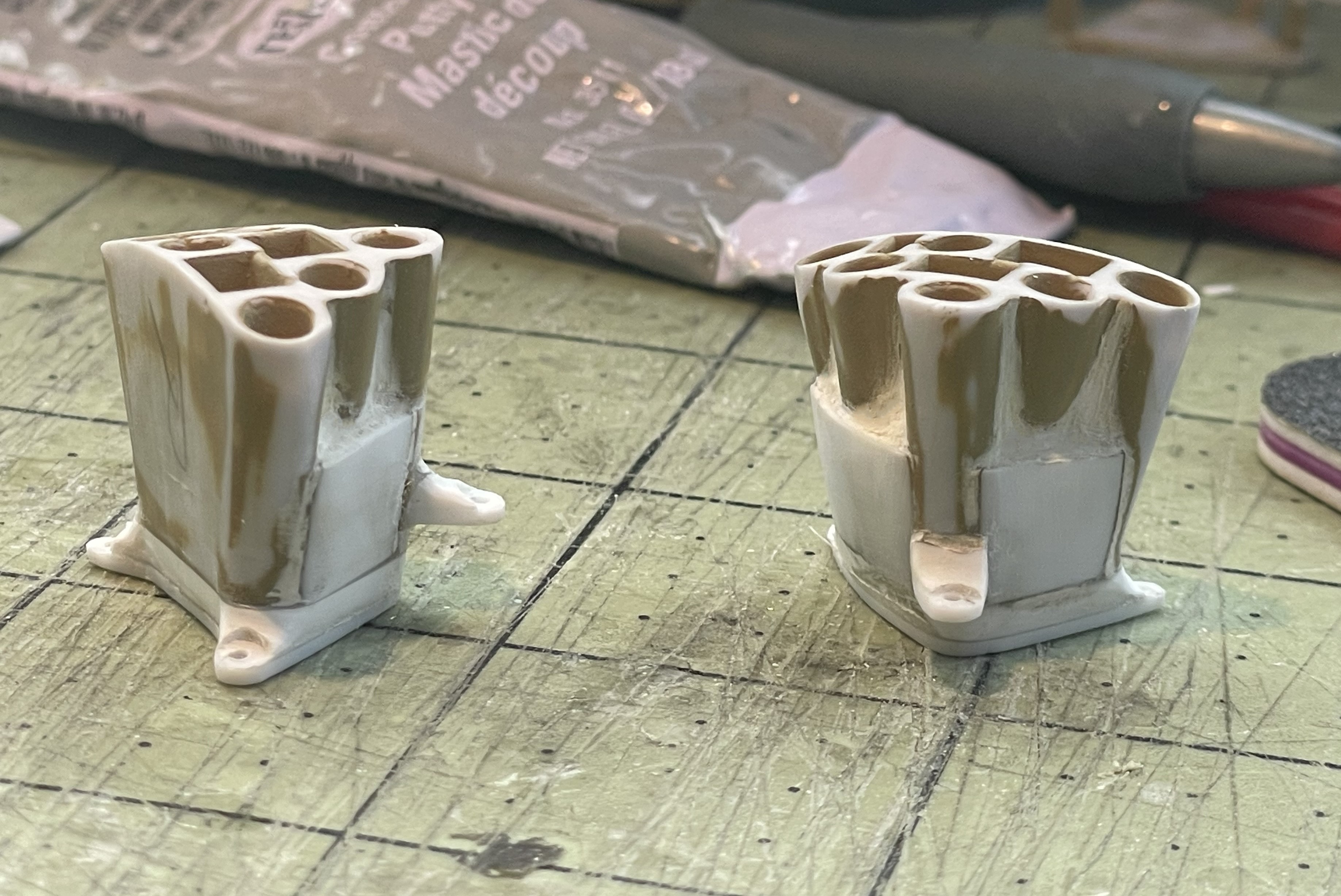
As seen in M-60A1 reference pictures that i am using, i also modified the two sides with the irregular piping to add a flat plate covering some of it from the bottom. Also added putty to give it a smooth joint and make the pipe joints a bit less deep, also seen in pictures. I carved the mount points. Then i probably polished them for a further two hours after this picture was taken.
- 1/16 RC USMC M-60A1 US tank with ERA - Build
- IMG_1170.JPG (1.37 MiB) Viewed 1132 times
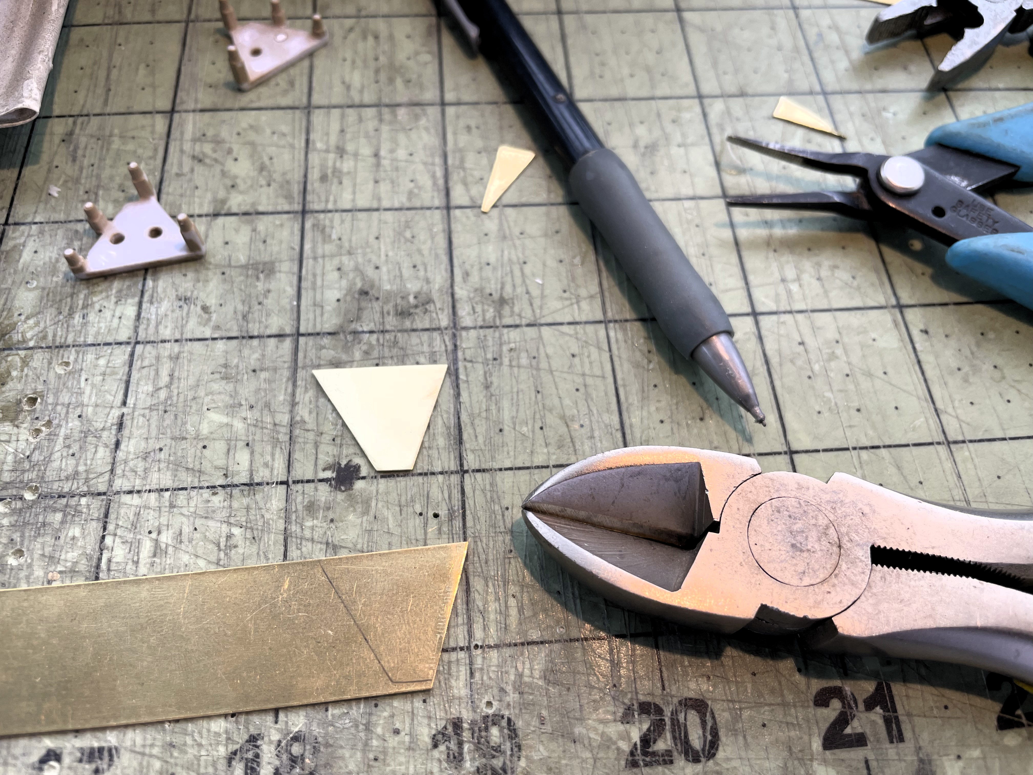
The core of the mount is a thin brass plate. i did my best to determine its shape using the dischargers and pictures. Be aware of left and right part at all times. I know the shape is not perfect but it will have to do. It is not a perfect V, one side has a stronger angle than the other.
- 1/16 RC USMC M-60A1 US tank with ERA - Build
- IMG_1147.JPG (2.45 MiB) Viewed 1132 times
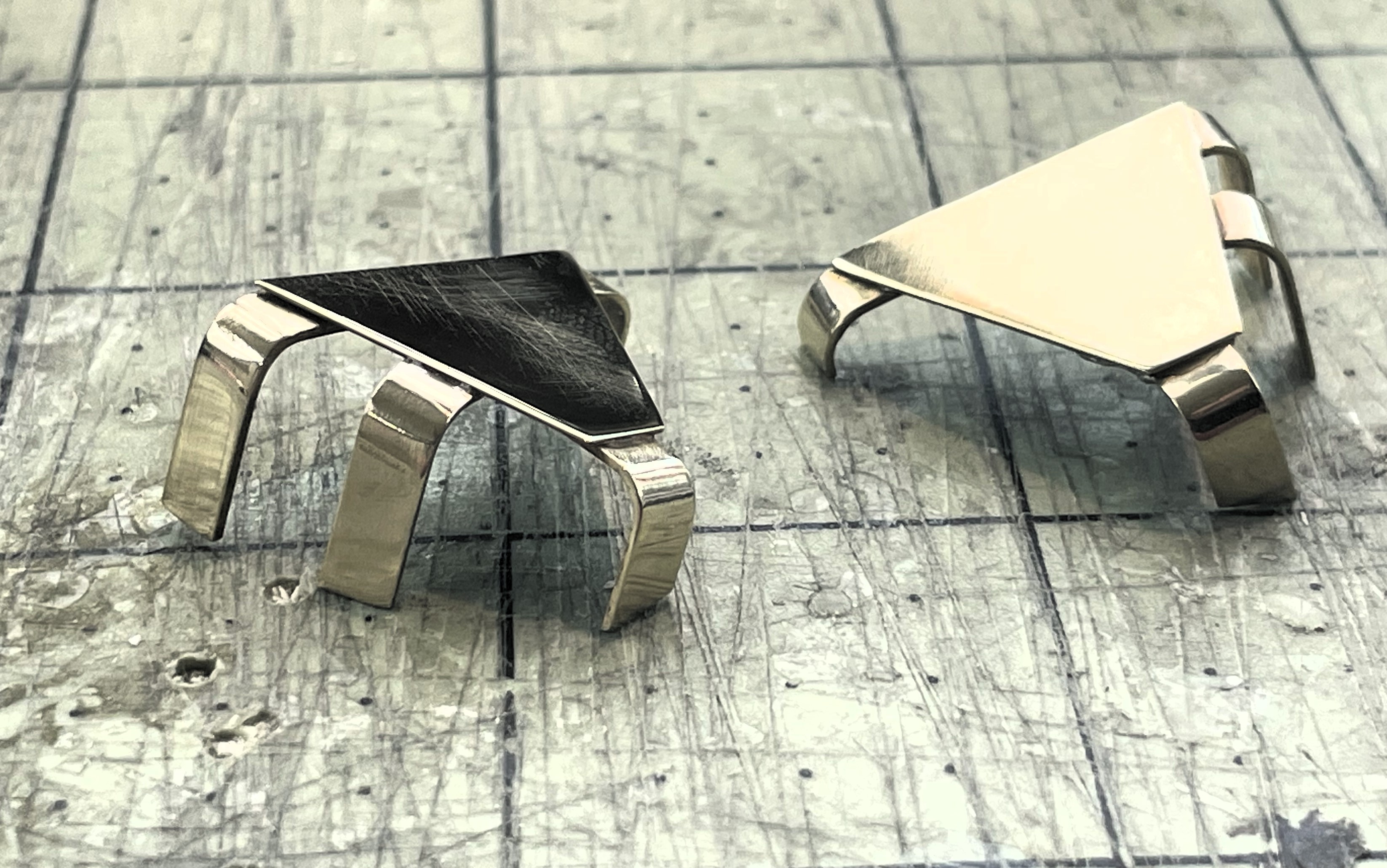
Then thick brass strips were cut and soldered under the plate for a really solid mount. Looking good compared to the plastic part provided. At the point, the legs are longer than they should. Each leg will be cut and filed to the proper length once dry fitting with the turret can be done after having calculated all the positioning points and angles in relation to the ERA blocks.
- 1/16 RC USMC M-60A1 US tank with ERA - Build
- IMG_1174.JPG (1.13 MiB) Viewed 1132 times
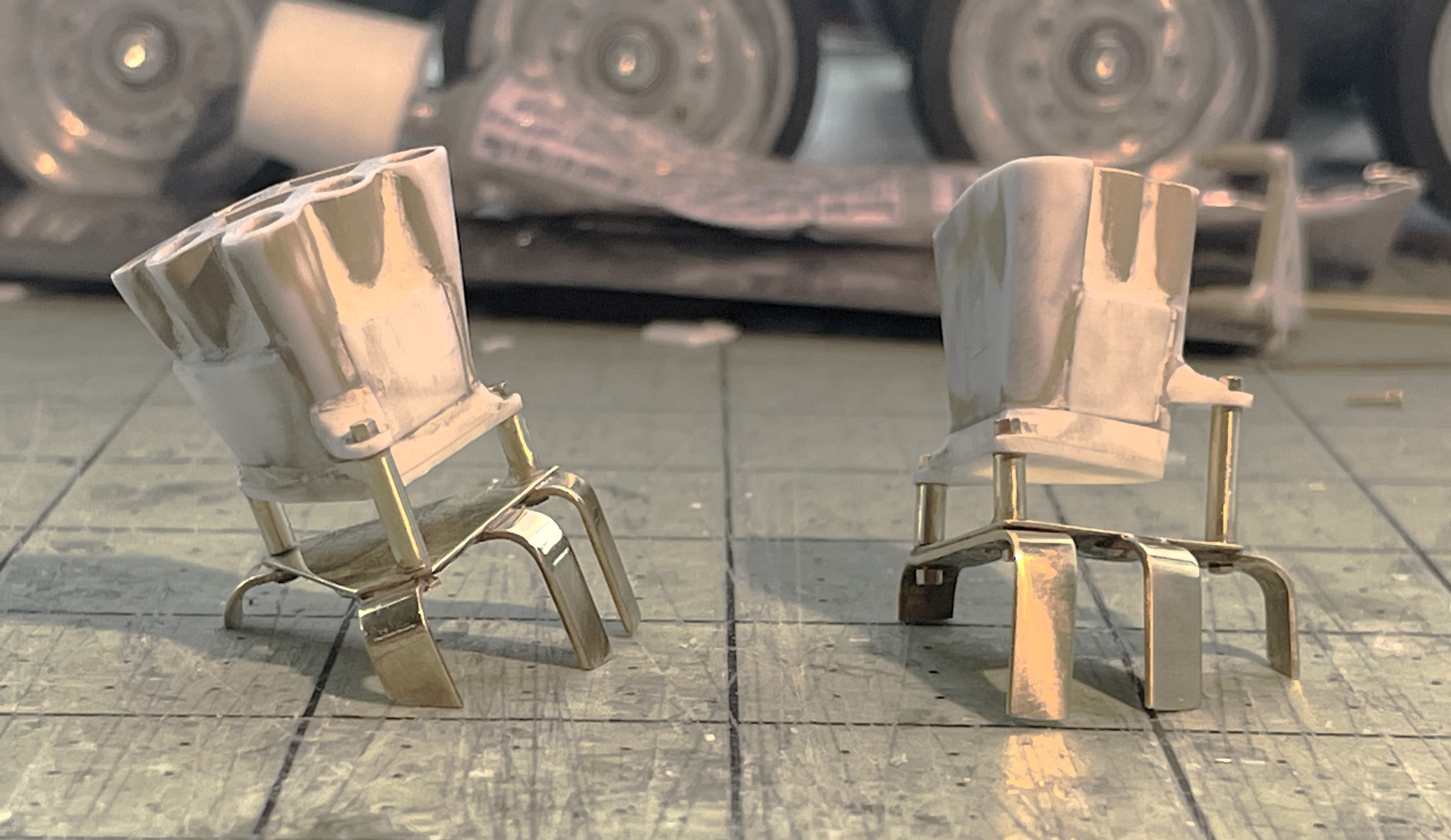
The dischargers are installed on their mounts. At this point, the legs have a basic shape that allow for dry fitting and then a series of adjustments.
- 1/16 RC USMC M-60A1 US tank with ERA - Build
- IMG_1194.JPG (1 MiB) Viewed 1132 times
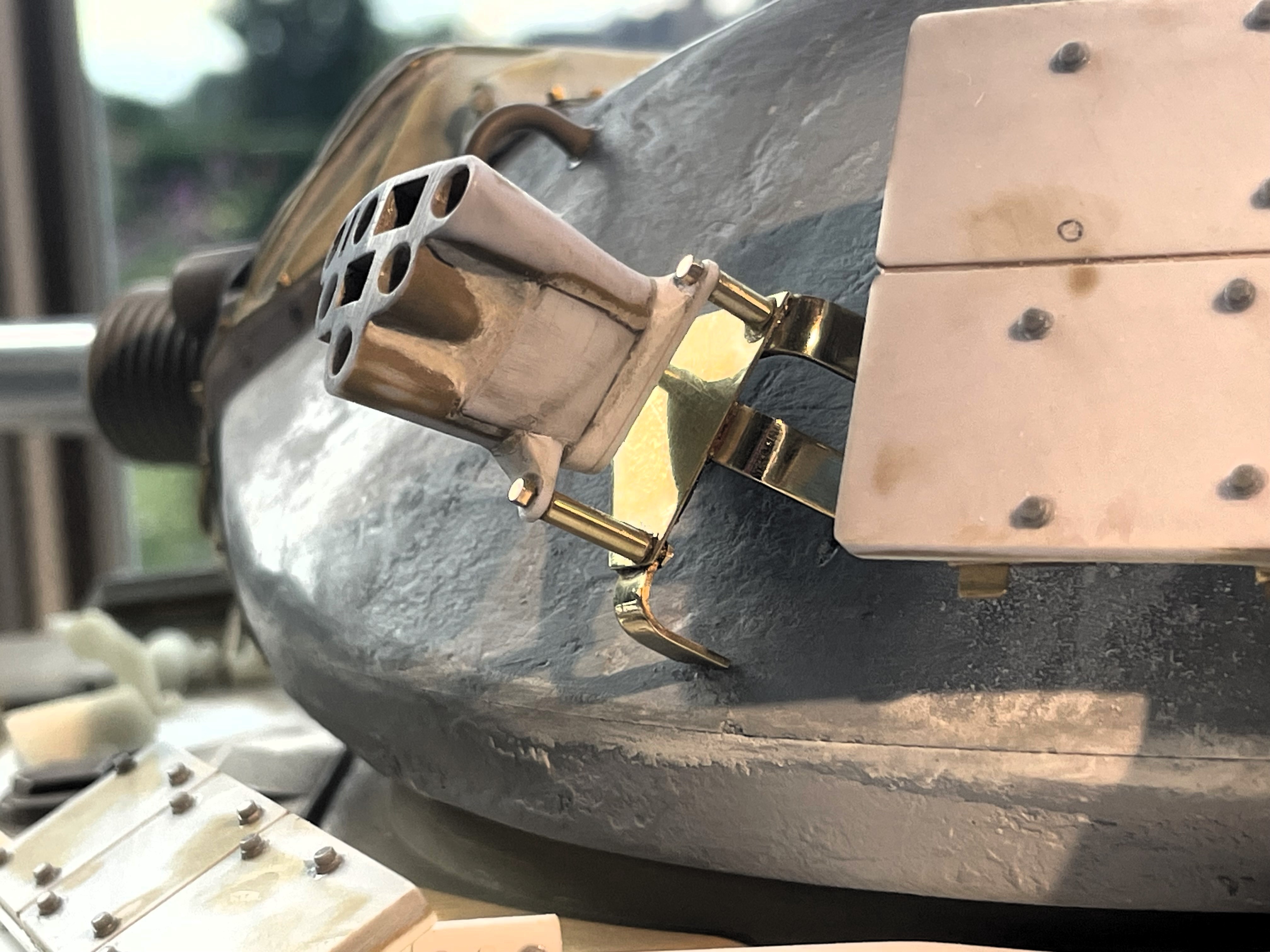
I have temporarily put the smoke grenade dischargers on the turret with a couple of superglue drops. It for display and analysis purposes. The dischargers cannot be permanently installed until i have installed the surrounding ERA blocks and determined the ultimate position for everything. There are so many variations as to where these dischargers can be mounted that it is currently impossible to determine exactly where. The fit between the ERA blocks is tight.
- 1/16 RC USMC M-60A1 US tank with ERA - Build
- IMG_1203.JPG (1.34 MiB) Viewed 1132 times
Continuing on following post