Building a Mid-Production Normandy Tiger 1

Post Reply
User avatar
tanks_for_the_memory
Sergeant
Posts: 501
Joined: Tue Jan 04, 2011 4:50 pm
Location: London

Re: Building a Mid-Production Normandy Tiger 1

Post by tanks_for_the_memory »

Thanks Sov!

Rear jack mounts
A shot of the Bovington Tiger I took at last year's Tankfest - a good view of the jack mounts as well as the early pattern mudguards.jpg
A shot of the Bovington Tiger I took at last year's Tankfest - a good view of the jack mounts as well as the early pattern mudguards.jpg (49.29 KiB) Viewed 8761 times
For some reason this was one part of the build that I wasn't looking forward to - but it proved to be very satisfying.

The HL jack is simply attached to the rear hull using two plastic pegs - so there are no visible mounts at all. It's also hollow underneath. The Tamiya jack, not surprisingly, is superior with good detail on both sides, but the brackets are simply 'U'-shaped pieces of metal which screw into the hull - hardly much better.

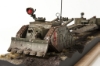
On the real Tiger the way in which the jack was held in place was actually a little more complicated than I first thought. Something I had overlooked was the fact that the weight of the jack actually rests on two fixed brackets beneath it. The function of the more prominent three-part hinged brackets was to clamp the tool against the back of the tank - not to bear its weight. These can both be seen clearly in the shot of the Bovington Tiger above. This arrangement changed very slightly when the 15-ton jack fitted to mid-production Tigers was up-graded for the steel-wheeled variant to the 20-ton one (the lower brackets moved slightly).
The Tiger jack actually rested on two brackets with slightly up-turned ends.jpg
The Tiger jack actually rested on two brackets with slightly up-turned ends.jpg (29.94 KiB) Viewed 8761 times
So how did I make the jack mounts? Actually it's SovereignZuul http://www.rctankwarfare.co.uk/forums/v ... 22&t=10204 I have to thank for a really useful tip when he was doing his jack mounts: using square plastic tube. The best size is 1/8" (otherwise described as 0.125" or 3.2mm x 3.2mm). Mine is made by Evergreen.

This has several advantages when it comes to building many of the mounts and brackets for tools on the Tiger 1. The original parts were often made from cast or bent thin metal - again see the Bovington Tiger pictured above - so that parts of them are quite three-dimensional.

Of course, because the tubing is made of plastic it is also much easier to carve or shape than metal. Also the square cross-section means that even when you cut it down to the depth of one side it has a rigidity that a simple flat strip of plastic card would never have.

Back to the brackets...

First I worked out where they should be attached to the rear plate and cut out a strip of zimmerit before adding cut-down plastic tubing to the hull. Here you can see the advantages of this square tubing - by leaving part of the sides intact I created the hinge mounts for the next section. It was only after I then presented the actual (Tamiya) jack that I realized that I had made a schoolboy error by lining up the right edge of the tool to the side of the rear plate rather than the rear corner of the side plate. So I had to shift them a little...
Relocated in their correct position, the rear portion of the jack clamps with holes drilled to accept the securing rods.jpg
Relocated in their correct position, the rear portion of the jack clamps with holes drilled to accept the securing rods.jpg (39.01 KiB) Viewed 8761 times
Next I shaped the lower and rear parts of the three-part brackets from the same square tubing.
The basic pieces for the back and bottom parts of the clamp carved from 3.2 x 3.2mm square plastic tube.jpg
The basic pieces for the back and bottom parts of the clamp carved from 3.2 x 3.2mm square plastic tube.jpg (29.01 KiB) Viewed 8761 times
Like the real ones they have to be different shapes and lengths because they fit around different parts of the actual jack. Unlike Sov's build I didn't plan to make these working brackets, but in order to look right it helps to make them as if they were going to be moveable.

The next stage was to wrap these pieces around the Tamiya jack itself, ensuring they lined up with the pieces I had already attached to the hull. For added strength I also cheated slightly by adding metal pegs to the rear of the lower jack brackets and drilling holes into the rear plate to take them.
This shows the Tamiya jack from beneath - this detail is missing from the HL part.jpg
This shows the Tamiya jack from beneath - this detail is missing from the HL part.jpg (27.09 KiB) Viewed 8761 times
Two lengths of metal rod were inserted into the rear of the new clamps to fit into corresponding holes drilled in the rear plate.jpg
Two lengths of metal rod were inserted into the rear of the new clamps to fit into corresponding holes drilled in the rear plate.jpg (32.18 KiB) Viewed 8761 times
More to follow...
Last edited by tanks_for_the_memory on Wed Jul 31, 2013 10:03 pm, edited 5 times in total.
My Mid-Production Normandy Tiger 1 build thread: http://www.rctankwarfare.co.uk/forums/v ... =22&t=8350
User avatar
tanks_for_the_memory
Sergeant
Posts: 501
Joined: Tue Jan 04, 2011 4:50 pm
Location: London

Re: Building a Mid-Production Normandy Tiger 1

Post by tanks_for_the_memory »

Jack brackets continued...
Two-thirds of the jack clamps have been installed and the metal pegs are in place to secure it to the hull.jpg
Two-thirds of the jack clamps have been installed and the metal pegs are in place to secure it to the hull.jpg (36.04 KiB) Viewed 8756 times
Once I had the lower and rear sections of the brackets glued to the jack itself I could mount it on the rear hull.
View from above shows jack firmly mounted and awaiting top part of clamps.jpg
View from above shows jack firmly mounted and awaiting top part of clamps.jpg (38.06 KiB) Viewed 8756 times
I was going to make the upper brackets from brass strip, but since the whole assembly already felt rock-solid I thought this unnecessary. So more plastic tube was cut to shape so that it fitted to make the missing side of the square. Into each of these a notch was cut where on the real thing a screw thread and butterfly nut held the brackets together.
Another view of the jack installed with completed clamps - except for the butterfly nuts.jpg
Another view of the jack installed with completed clamps - except for the butterfly nuts.jpg (31.93 KiB) Viewed 8756 times
Another view from underneath.jpg
Another view from underneath.jpg (25.77 KiB) Viewed 8756 times
Finally I added the fixed brackets underneath the jack. Because these have slightly upturned ends I made them from brass strip with triangular fillets from plastic card.
The three-piece clamps now in place - awaiting butterfly screws. Note mounting blocks for Feifel air cleaners above.jpg
The three-piece clamps now in place - awaiting butterfly screws. Note mounting blocks for Feifel air cleaners above.jpg (24.97 KiB) Viewed 8756 times
The final touch (almost) was to add the butterfly/wing nuts and the jack handle itself. I will discuss the butterfly nuts further below, but these are by Schumo: beautifully cast in metal complete with threaded screws. I thought I really had to use metal pieces here because they sit on such an exposed part of the tank - especially during any careless reversing!
Finished jack mounts - note mounts for Feifel air cleaners above.jpg
Finished jack mounts - note mounts for Feifel air cleaners above.jpg (28.86 KiB) Viewed 8756 times
Finished jack mounts with Schumo butterfly nuts added - all that's missing is the clamp holding the lever against the rear hull.jpg
Finished jack mounts with Schumo butterfly nuts added - all that's missing is the clamp holding the lever against the rear hull.jpg (28.17 KiB) Viewed 8756 times
Finished jack mounts with Schumo butterfly nuts added - the only thing to be added is the clamp holding the lever against the rear hull.jpg
Finished jack mounts with Schumo butterfly nuts added - the only thing to be added is the clamp holding the lever against the rear hull.jpg (27.38 KiB) Viewed 8756 times
All that's left is the small clamp which holds the handle against the hull. That's going to have to wait because I have some far more challenging clamps to build first - the ones which hold the towing cables in place...
Last edited by tanks_for_the_memory on Sun Jun 09, 2013 11:32 pm, edited 1 time in total.
My Mid-Production Normandy Tiger 1 build thread: http://www.rctankwarfare.co.uk/forums/v ... =22&t=8350
User avatar
ska2d2
Private
Posts: 81
Joined: Sat Feb 23, 2013 12:04 pm
Location: Leeds W Yorkshire

Re: Building a Mid-Production Normandy Tiger 1

Post by ska2d2 »

Very nice fella! :clap:
User avatar
SovereignZuul
Corporal
Posts: 453
Joined: Sat Aug 25, 2012 11:50 pm
Location: Connecticut, USA

Re: Building a Mid-Production Normandy Tiger 1

Post by SovereignZuul »

8O Amazing on the jack mount! Superb! I'm jealous, hehe.

Where do you get Schumo parts? Their website is down (http://www.schumo-kits.com/) and I can't find anything with google strangely enough.
I'd love to get some wingnuts for my cleaning rod/tow cable bracket.
User avatar
tanks_for_the_memory
Sergeant
Posts: 501
Joined: Tue Jan 04, 2011 4:50 pm
Location: London

Re: Building a Mid-Production Normandy Tiger 1

Post by tanks_for_the_memory »

Thanks gents!

Schumo butterfly / wingnuts are available as I type - in the UK at least - from Tankzone or Welshdragon. Tankzone are the cheapest - free postage - sorry Steve! Still £4.50 for a mere 6 mind...
My Mid-Production Normandy Tiger 1 build thread: http://www.rctankwarfare.co.uk/forums/v ... =22&t=8350
User avatar
buckeye36
Lance Corporal
Posts: 188
Joined: Sat May 01, 2010 7:29 pm
Location: EHT, NJ

Re: Building a Mid-Production Normandy Tiger 1

Post by buckeye36 »

Great work!
Tamiya Tiger 1, Tamiya M4 (105) HVSS, Tamiya Jagdpanther G1, ElMod Jagdpanther G2, ElMod KV-1E, ElMod StuG 40 G
User avatar
tanks_for_the_memory
Sergeant
Posts: 501
Joined: Tue Jan 04, 2011 4:50 pm
Location: London

Re: Building a Mid-Production Normandy Tiger 1

Post by tanks_for_the_memory »

Thanks Buck!

Well, on with the show...

Towing cables and brackets
Front towing cable brackets with Taigen cables installed - soon to be replaced by Schumo.jpg
Front towing cable brackets with Taigen cables installed - soon to be replaced by Schumo.jpg (36.03 KiB) Viewed 8683 times
The large towing cables are a distinctive part of the Tiger’s tool stowage. They had to be long and very strong so that between them they could take the weight of the tank (or another if, as they often did, they were towing a crippled Tiger).

The HL cables are more or less a straight copy of the Tamiya ones. Both come moulded as one piece complete with the front and middle brackets – the latter incorporating the barrel cleaning rods. Like the moulded-on tools they scrub up quite well with a decent paint job. However, they are a little over-thick, lacking in detail and, for some reason, don’t even line up with the attachment points for the middle brackets moulded into the hull roof. They also lack the rear clamps (two each side) which are located on the engine deck – and these are missing from the Tamiya versions as well.

So what are the options? Several manufacturers make tow cables, either moulded in one piece, ready-made with real twisted wire or as a kit with wire, separate eyelets and sleeves. However, none of these come with the clamps which actually hold them to the top deck. There is, of course, the Aber option – but I believe these are only available as part of a complete up-grade kit (expensive) and – like most Aber photoetch – not easy to make up.

My first choice for the towing cables themselves was to go for the Taigen ready-mades and it is these you will see in the first photos. However, I soon discovered that they also have issues: first, they are slightly too thick, second, they have a bit too much 'spring' - making them hard to keep in place. A third problem, which was probably my own fault, was that they were too long. In fact it turns out that I must have bought the Tiger II cables by mistake - they are 70cms long, whereas the Tiger 1 ones should be 60. So I have purchased the Schumo set instead, which also are a little thinner and, to my eye, more to scale. More of these later...

As I soon realized, however, the cables were the least of my worries: once you do away with the all-in-one plastic cables you also do away with the brackets which attach them to the hull roof. Making these brackets seemed a daunting enough task in itself - until I also faced up to the fact that the cables would have to be detachable just like the real thing. After all, the real Tiger was painted and camouflaged without them in place. They also had to be strong enough to keep the heavy cable clamped in place on the deck - so that is what I was going to have to do!
Front brackets finished off with the Schumo butterfly nuts - all they need is a little bedding in with Milliput weld beads.jpg
Front brackets finished off with the Schumo butterfly nuts - all they need is a little bedding in with Milliput weld beads.jpg (25.22 KiB) Viewed 8683 times
The four front brackets are the trickiest. Essentially they each consist of three parts: two metal pillars, one with a hinge, the other a butterfly nut on a screw and between them a hinged bar which keeps the eyelet clamped to the deck.
The forward part of each bracket with dress pins inserted.jpg
The forward part of each bracket with dress pins inserted.jpg (32.56 KiB) Viewed 8683 times
Once again the square section plastic tube - the same type I had used for the jack brackets - came to my rescue. First the four pieces for the forward end of the bracket were cut to the required height. One side was cut away - the side facing aft which will not be seen once the cables are installed - and the top sanded to a rounded profile. I then drilled a hole for the hinge and inserted a dress-making pin. These pins are excellent - cheap, uniform and strong. They are going to come in very useful! They should be found in any haberdashery store - for those of us in the UK they are cheaply available at Wilkinsons.
The rear part of each bracket was cut from the same square plastic tube.jpg
The rear part of each bracket was cut from the same square plastic tube.jpg (60.44 KiB) Viewed 8683 times
The rear part of each bracket was trimmed from the same square tube - this time laying flat. Here I cheated a little because on the real vehicle this part of the bracket has a threaded bolt mounted on a swivel mount to allow it to be raised to meet the butterfly nut - I planned simply to drill a hole into the hull to take the thread of the Schumo part.
For the clamp itself the end of a brass strip was filed narrower, then bent around a drill bit.jpg
For the clamp itself the end of a brass strip was filed narrower, then bent around a drill bit.jpg (68.11 KiB) Viewed 8683 times
The end once bent should look a bit like this.jpg
The end once bent should look a bit like this.jpg (31.04 KiB) Viewed 8666 times
Dress making pins inserted but yet to be trimmed.jpg
Dress making pins inserted but yet to be trimmed.jpg (33.15 KiB) Viewed 8683 times
The moveable part of the bracket was made from brass strip. One end was filed so that it fitted between the top of the sides of the forward bracket, then bent so that it would tuck under the dress pin I had already inserted. It took a little trial and error, but eventually I arrived at a working hinge. Note that, just like the real thing, this part is slightly bent to allow for the fact that the forward part of the hinge is higher than the rear.
Finished brackets.jpg
Finished brackets.jpg (34.57 KiB) Viewed 8683 times
Positioning everything on the top of the hull was another stress. Scale drawings help, of course, but I also had to ensure that the brackets did not foul the opening hatches. My initial attempts proved to be way out...
Small tacks were inserted into holes drilled in the hull roof to provide an achor for the plastic brackets.jpg
Small tacks were inserted into holes drilled in the hull roof to provide an achor for the plastic brackets.jpg (21.57 KiB) Viewed 8683 times
Also, because I was worried about the strength of the brackets versus the Taigen cables, I glued them to tacks inserted into holes drilled into the hull top. However, after they had been fixed into place I wondered if this was necessary, especially once I had also inserted the Schumo butterfly nuts.
Finished starboard side front cable brackets.jpg
Finished starboard side front cable brackets.jpg (25.07 KiB) Viewed 8683 times
Last edited by tanks_for_the_memory on Thu Jul 11, 2013 1:14 am, edited 9 times in total.
My Mid-Production Normandy Tiger 1 build thread: http://www.rctankwarfare.co.uk/forums/v ... =22&t=8350
User avatar
Wildboar44
Corporal
Posts: 392
Joined: Sun Jan 13, 2013 10:28 pm
Location: Kent England UK.

Re: Building a Mid-Production Normandy Tiger 1

Post by Wildboar44 »

.
Dear Gentleman Tim..... I think your build is moving into the art category .... you and Derek just keep raising the bar ! . Pure class Ace 8)
Yesterday is our history, Tomorrow is an eternal mistery, Today is a gift, its why its called "The Present".
User avatar
tanks_for_the_memory
Sergeant
Posts: 501
Joined: Tue Jan 04, 2011 4:50 pm
Location: London

Re: Building a Mid-Production Normandy Tiger 1

Post by tanks_for_the_memory »

Here are some pictures showing the real cable brackets and clamps - they are either my photos from the surviving Tigers at Vimoutiers and Saumur or they come from the Modeler's Guide to the Tiger book.

In the first photo (from the Vimoutiers Tiger) the upper clamp bracket appears to be upside down. Sloppy workmanship?!
[Actually I shouldn't joke - by this stage of the war a lot of these tanks were being built using slave labour...]
My own shot of the clamps on the Vimoutiers Tiger 1.jpg
My own shot of the clamps on the Vimoutiers Tiger 1.jpg (45.11 KiB) Viewed 8592 times
My own photo of the Saumur Tiger 1 cable brackets in close-up.jpg
My own photo of the Saumur Tiger 1 cable brackets in close-up.jpg (32.92 KiB) Viewed 8592 times
Front cable clamps on the Bovington Tiger.jpg
Front cable clamps on the Bovington Tiger.jpg (25.7 KiB) Viewed 8665 times
3 views of the gun cleaning rod and cable brackets from the Bovington Tiger.jpg
3 views of the gun cleaning rod and cable brackets from the Bovington Tiger.jpg (20.15 KiB) Viewed 8665 times
My own shot of the rear cable clamps on the Saumur Tiger 1.jpg
My own shot of the rear cable clamps on the Saumur Tiger 1.jpg (30.47 KiB) Viewed 8592 times
Cable clamps from the Tiger II were essentially the same as those on the Tiger 1.jpg
Cable clamps from the Tiger II were essentially the same as those on the Tiger 1.jpg (31.77 KiB) Viewed 8665 times
Again this is a Tiger II bracket - but identical to the four cable clamps on the Tiger 1 engine deck.jpg
Again this is a Tiger II bracket - but identical to the four cable clamps on the Tiger 1 engine deck.jpg (25.53 KiB) Viewed 8665 times
My own photo of the Saumur Tiger II cable brackets in close-up - identical to those at the front of the Tiger 1.jpg
My own photo of the Saumur Tiger II cable brackets in close-up - identical to those at the front of the Tiger 1.jpg (34.28 KiB) Viewed 8592 times
And here's that Aber set. Very lovely - the price less so: just shy of £60!
Aber TI0021 High Grade Cable Holders set.jpg
Aber TI0021 High Grade Cable Holders set.jpg (68.37 KiB) Viewed 8638 times
Last edited by tanks_for_the_memory on Wed Sep 10, 2014 11:33 pm, edited 8 times in total.
My Mid-Production Normandy Tiger 1 build thread: http://www.rctankwarfare.co.uk/forums/v ... =22&t=8350
User avatar
tanks_for_the_memory
Sergeant
Posts: 501
Joined: Tue Jan 04, 2011 4:50 pm
Location: London

Re: Building a Mid-Production Normandy Tiger 1

Post by tanks_for_the_memory »

On with the cable clamps...

The rear brackets are the simplest.
For the rear cable clamps I started by filing 4 U-shaped depressions in a piece of thick plastic square rod.jpg
For the rear cable clamps I started by filing 4 U-shaped depressions in a piece of thick plastic square rod.jpg (35.25 KiB) Viewed 8495 times
Next I drilled holes for each end of the clamps.jpg
Next I drilled holes for each end of the clamps.jpg (31.39 KiB) Viewed 8495 times
Dress making pins were then inserted into one end of each clamp.jpg
Dress making pins were then inserted into one end of each clamp.jpg (70.23 KiB) Viewed 8495 times
Four large parcel staples were then cut to length, drilled and held in place with the pins.jpg
Four large parcel staples were then cut to length, drilled and held in place with the pins.jpg (13.95 KiB) Viewed 8495 times
Now separated, the pins were then cut shorter and each staple segment had a notch cut into one end.jpg
Now separated, the pins were then cut shorter and each staple segment had a notch cut into one end.jpg (33.29 KiB) Viewed 8491 times
One side of each clamp was then cut away for the folding butterfly screws would be fitted.jpg
One side of each clamp was then cut away for the folding butterfly screws would be fitted.jpg (35.16 KiB) Viewed 8495 times
Rear clamps before tow rope and butterfly nuts installed.jpg
Rear clamps before tow rope and butterfly nuts installed.jpg (31.68 KiB) Viewed 8495 times
And here they are with the tow rope and butterfly nuts added.jpg
And here they are with the tow rope and butterfly nuts added.jpg (37.1 KiB) Viewed 8495 times
In photos of the real thing you often see the rear deck hatch hooks over the tow ropes like this.jpg
In photos of the real thing you often see the rear deck hatch hooks over the tow ropes like this.jpg (36.43 KiB) Viewed 8495 times
Another view.jpg
Another view.jpg (32.94 KiB) Viewed 8495 times
Because the Taigen tow ropes are a bit on the thick side the clamps sit a little too high - so I am expecting the Schumo ropes to look better (once I get round to making them up!)

Also, like all of these fittings to the Tiger, they will need to be bedded in with Milliput weld beads.
Last edited by tanks_for_the_memory on Thu Jul 04, 2013 12:45 am, edited 5 times in total.
My Mid-Production Normandy Tiger 1 build thread: http://www.rctankwarfare.co.uk/forums/v ... =22&t=8350
Post Reply

Return to “Tiger I”