Scratchbuilding C&Cs Mammoth Tank
Re: Scratchbuilding C&Cs Mammoth Tank
I daren't look a my bank account and try and avoid looking if possible. It's looking good and England recovered to 342-6 by the end of day. Not bad at all.

Re: Scratchbuilding C&Cs Mammoth Tank
Yeah my bank wasn't as nice a sight as I wa hoping for. Still, the bills are all paid and I've managed to cover the metal for my track pins! Will be paying that in the next few days and the guy is sending me a few different diameter samples before shipping out the whole 21meters just to check I get the best possible fit!
Re: Scratchbuilding C&Cs Mammoth Tank
Apologies for the long absence, I've been working on another project for some time and waiting for my delivery of the correct wire to finish the tracks. It finally arrived anyway (after getting the first order sent to me wrong!) and it seems to do the job well enough. The smaller gauge of wire the guy sent me as a sample was too thin to use and simply slipped right through the holes in the track. The larger of the two was a little over-sized so that wasn't really ideal either but with no gauge between 18 and 19 I had to go with the slightly big one!
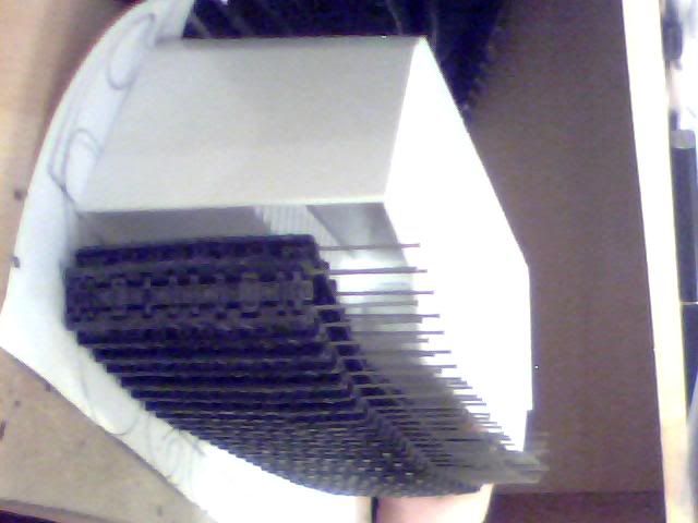
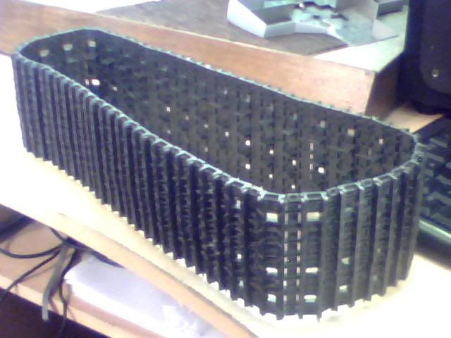
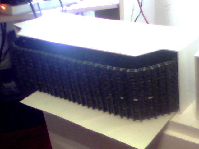
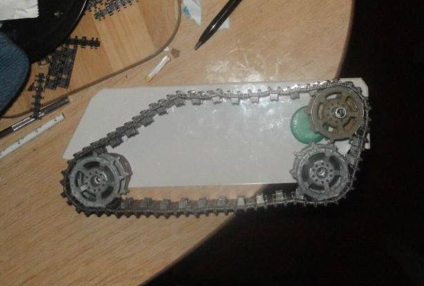
Since then I've removed the original trackpins from the length I'd previously completed and now replaced them all with the new wire. The result is a track that has a lot more strength and pins that are the right size for it but the downside is it's a little less flexible than I'd like. Any normal track is pretty much completely floppy for example, mine is semi-rigid in that it can hold strange shapes and angles if setup in a certain way. It does work in the way it's intended to when sprockets are fitted however so I think it'll do the job just fine when it's finished and over time it should get smoother and smoother. I just have to be sure the track is always kept tight so there are no ugly kinks but that said most of it will be hidden from view and the visible part will be carrying all the weight of the vehicle so should be fine!
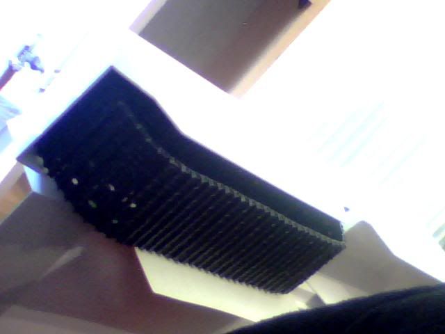
Anyway here are some pics of the finished track, remember it's only one of 4 that I need to make for the final build! They aren't particularly inspiring pics but it's a vast improvement over it's appearance when I was still using two of the old pins...
And here is is fitted into the armour very roughly.

While I'm posting I need to request a trade for some parts I currently have! You may remember I received a humongous delivery of track parts a while back including 12 drive wheels. I've found a way to use the parts I have to build all 4 tracks but I discovered not too long ago that 6 of the sprockets I have are slightly different. Here are the pics.
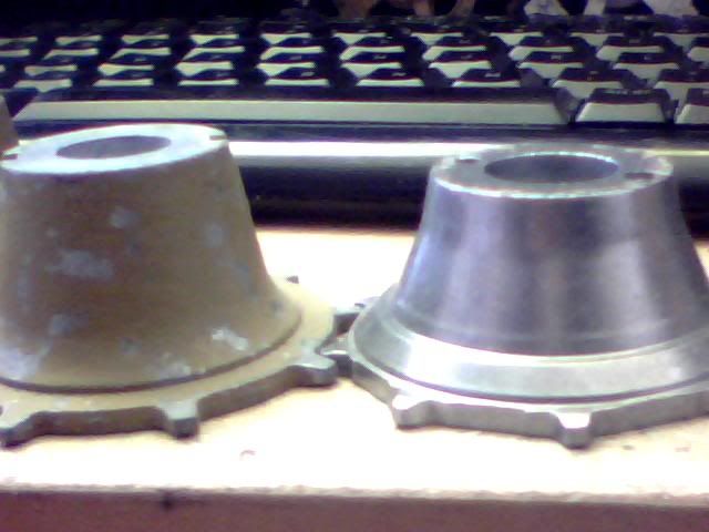
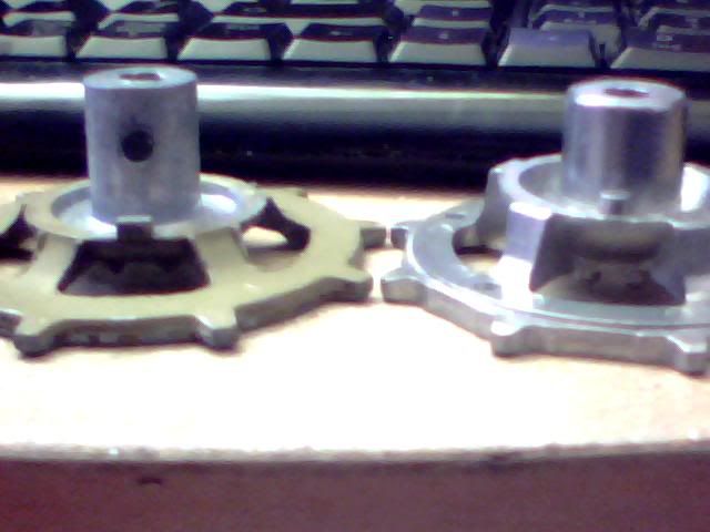
Now I can make do with 2 different sets due to how this build will all come together but I'd MUCH rather have 12 that are all the same. The ones I would like are those with the square tabs as opposed to the round pegs. If anyone has 6 of these that they would be able to trade with me I'd be very appreciative! Alternatively if someone wants to buy a few of these so I can buy some more of the ones I want elsewhere that would work too :p
There's also another thing on the wishlist which is going to prevent me carrying on with this build which is the custom driveshafts I noted a few posts back. I know someone here said they actually do turning for a living but they were super-busy right now. Whoever it was please hit me up with a PM as this project is on-hold until I find someone who can do this for me! Alternatively, let me know if there's anyone else who's known to the site who offers a similar service as this is my next step.
I'm going to post up on another website what I'm after as they may be able to help too but just as a reminder, this is what I'm wanting and I'll need 4! The thinner end which for some reason I didn't mark needs to be about 25mm long so the whole thing should be 120mm from end to end.
Since then I've removed the original trackpins from the length I'd previously completed and now replaced them all with the new wire. The result is a track that has a lot more strength and pins that are the right size for it but the downside is it's a little less flexible than I'd like. Any normal track is pretty much completely floppy for example, mine is semi-rigid in that it can hold strange shapes and angles if setup in a certain way. It does work in the way it's intended to when sprockets are fitted however so I think it'll do the job just fine when it's finished and over time it should get smoother and smoother. I just have to be sure the track is always kept tight so there are no ugly kinks but that said most of it will be hidden from view and the visible part will be carrying all the weight of the vehicle so should be fine!
Anyway here are some pics of the finished track, remember it's only one of 4 that I need to make for the final build! They aren't particularly inspiring pics but it's a vast improvement over it's appearance when I was still using two of the old pins...
And here is is fitted into the armour very roughly.
While I'm posting I need to request a trade for some parts I currently have! You may remember I received a humongous delivery of track parts a while back including 12 drive wheels. I've found a way to use the parts I have to build all 4 tracks but I discovered not too long ago that 6 of the sprockets I have are slightly different. Here are the pics.
Now I can make do with 2 different sets due to how this build will all come together but I'd MUCH rather have 12 that are all the same. The ones I would like are those with the square tabs as opposed to the round pegs. If anyone has 6 of these that they would be able to trade with me I'd be very appreciative! Alternatively if someone wants to buy a few of these so I can buy some more of the ones I want elsewhere that would work too :p
There's also another thing on the wishlist which is going to prevent me carrying on with this build which is the custom driveshafts I noted a few posts back. I know someone here said they actually do turning for a living but they were super-busy right now. Whoever it was please hit me up with a PM as this project is on-hold until I find someone who can do this for me! Alternatively, let me know if there's anyone else who's known to the site who offers a similar service as this is my next step.
I'm going to post up on another website what I'm after as they may be able to help too but just as a reminder, this is what I'm wanting and I'll need 4! The thinner end which for some reason I didn't mark needs to be about 25mm long so the whole thing should be 120mm from end to end.
Re: Scratchbuilding C&Cs Mammoth Tank
Great work on your project Munty, hope you haven't given up on it yet even though its been 1 1/2 years since your last update.
What I have to write is all based on the presumption that your still stuck with the incorrect shaft length issue.

Note: Uneven lines are meant to depict that thinning of the shaft doesn't have to be perfect or straight.
First thin out the shaft with a dremel enough so that you can fit a tube:
http://www3.towerhobbies.com/cgi-bin/wt ... XBJXN&P=FR around it and that the tube is free to move until is concentric/parallel to the shaft. Then add a high strength epoxy (not sure if JBWeld (black/red tubes) is available in UK) and glue the shaft inside while maintaining straight edge. Shave/cut off excess epoxy that could get in the way.
With the straight edge as long as two sides of the shaft are touching the V shape you pretty much have an aligned shaft. This is best done with a rigid right angle. Could be a miter box or something similar. Just make sure you leave a sheet of copy paper or something between your shaft and the miter box so you epoxy your shaft to it.
http://www.micromark.com/miter-box-for- ... ,6752.html
I would use something like this:


Hope this helped and you can finish it to come back with some awesome results!
What I have to write is all based on the presumption that your still stuck with the incorrect shaft length issue.
Note: Uneven lines are meant to depict that thinning of the shaft doesn't have to be perfect or straight.
First thin out the shaft with a dremel enough so that you can fit a tube:
http://www3.towerhobbies.com/cgi-bin/wt ... XBJXN&P=FR around it and that the tube is free to move until is concentric/parallel to the shaft. Then add a high strength epoxy (not sure if JBWeld (black/red tubes) is available in UK) and glue the shaft inside while maintaining straight edge. Shave/cut off excess epoxy that could get in the way.
With the straight edge as long as two sides of the shaft are touching the V shape you pretty much have an aligned shaft. This is best done with a rigid right angle. Could be a miter box or something similar. Just make sure you leave a sheet of copy paper or something between your shaft and the miter box so you epoxy your shaft to it.
http://www.micromark.com/miter-box-for- ... ,6752.html
I would use something like this:
Hope this helped and you can finish it to come back with some awesome results!
Re: Scratchbuilding C&Cs Mammoth Tank
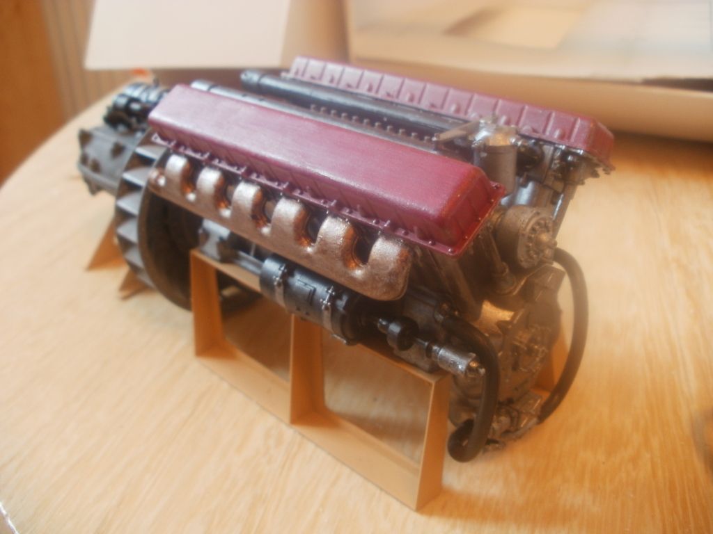
Hey Nothgrim thanks so much for your input! I'm really excited about giving this method a try and will certainly start doing my homework into what sort of materials are available for this sort of job in the uk! I've clearly not been overly busy on this project lately for many reasons but I did bring it downstairs for a month or so not long back and started work on some of the interior detailing for the engine room which it seems I never posted up. Your new reply has made me bring the sucker down again to have a look into the feasibility of your suggestion but before I go into all of that here are some piucs of the engine I managed to complete last time. I'll add wires for detail and will need to do something ingenious with the radiators too (as this is from a T-34 kit so the rads are flank mounted) but for now it's come up pretty nicely! Just need to find a way to make it more visible when the tank is all put together...
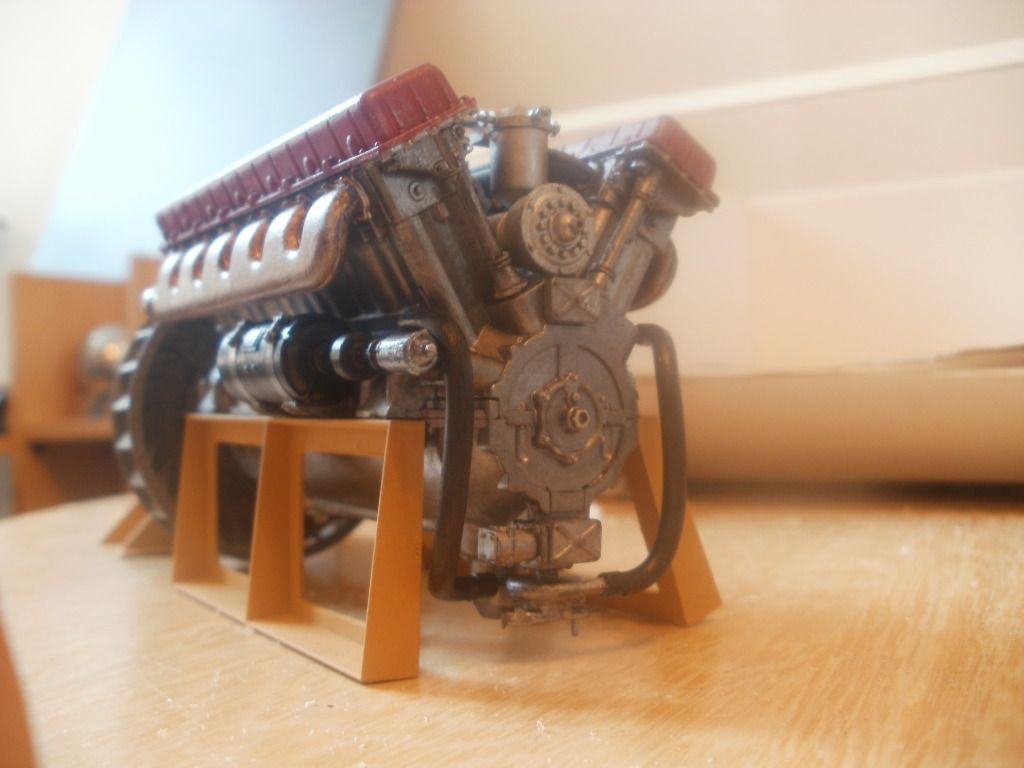
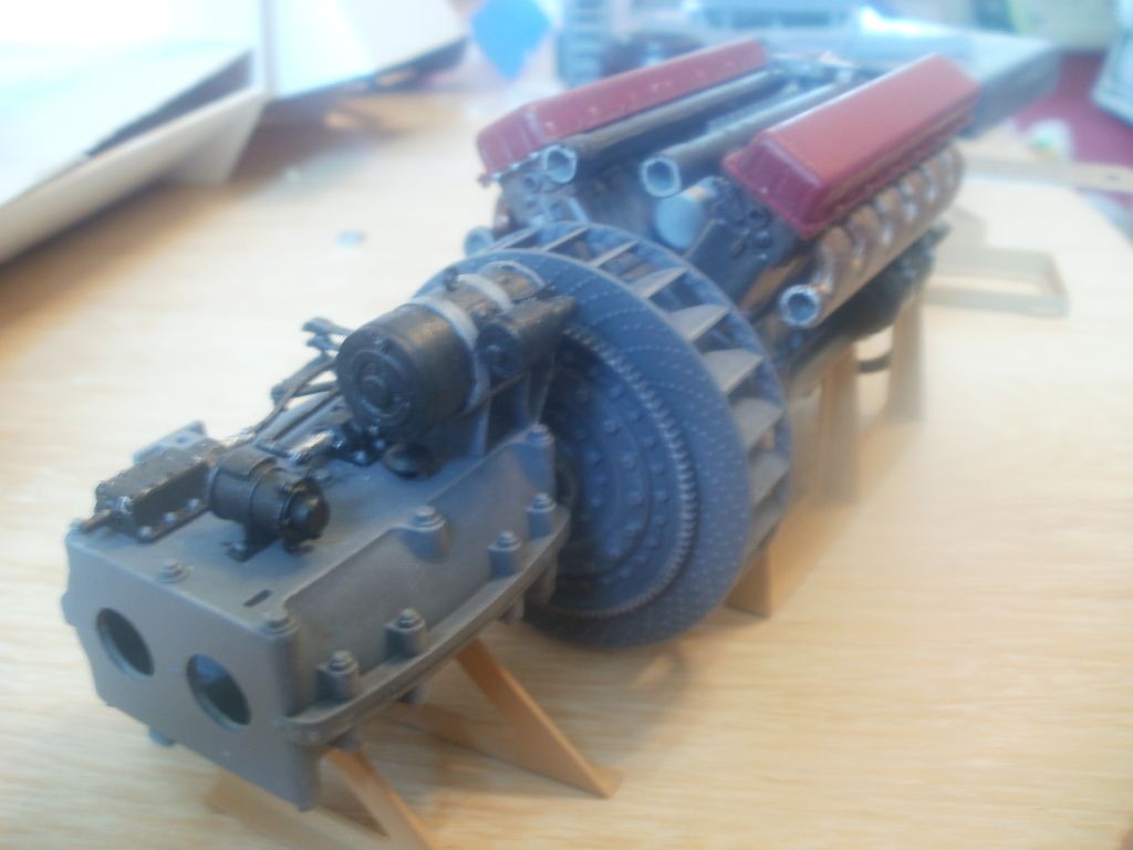
And here it is mocked up with the ancilliaries like the starter motor and such.
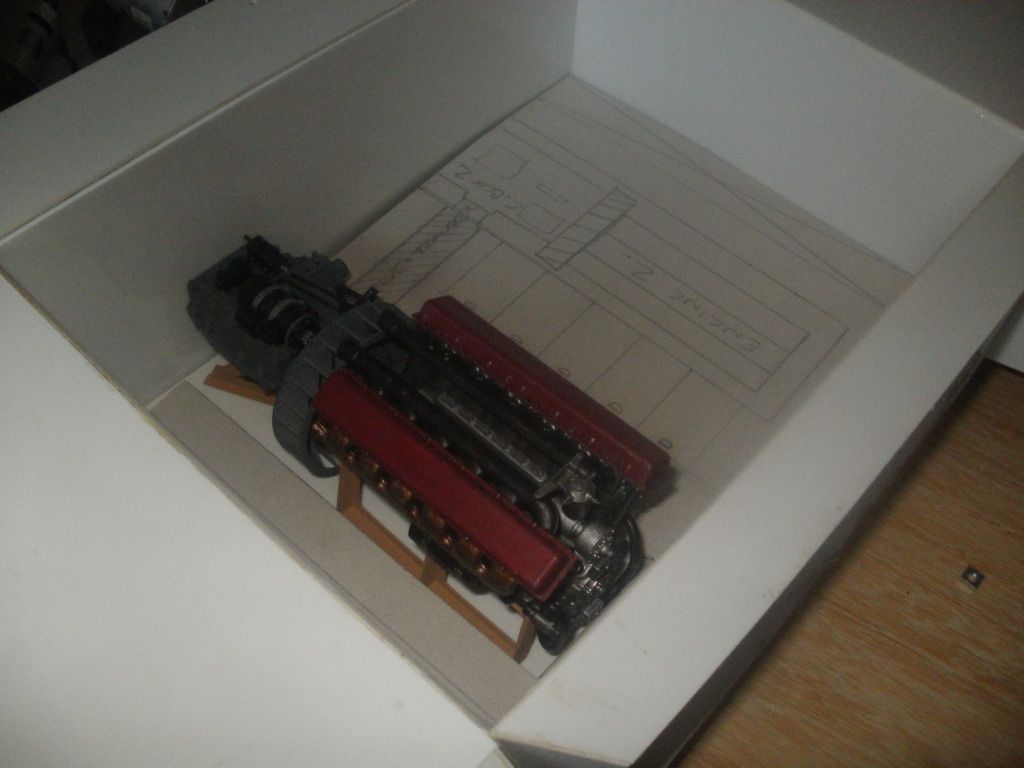
The other engine will be mounted with the gearbox rotated 180o and both will be joined with a driveshaft and differential which would allow one engine to drive a single track on each side of the vehicle if one powerplant were to fail. This prevents it being immobilised but I guess it wouldn't be going anywhere fast! The floor will be a kind of raised grating as illustrated before and the walls will be detailed with some kitbashing most likely, fuels tanks on left and right sides.
Anyway! That really is pretty much all I've done since last time I discussed this so it's time to solve the problem of these driveshafts now. I've been re-organising the house lately as the missus and I have finally decided we're better off apart which leaves me with a nice spot in the lounge for a 'Mammoth table' which I'm in the process of assembling as we speak... Hopefully walking past it everyday will encourage me to do something about it but I AM notoriously wishy washy so fingers crossed on that one...
All that stuff aside though, I have some answers for you as promised in PM Nothgrim! Thought they were better posted here as it took me quite a lot of work to actually discover this info in the first place so if I can save others the time of doing so then all the better!
So first off, the question was regarding how to scale this beast into 1:16 which I used because it's the RC tank standard of course... Documentation on fictional objects and vehicles from games and other media doesn't tend to have much of a grey area. Something is either very well documented or not documented at all. Sadly, the Mammoth tank has virtually no information available anywhere other than the images and blurb that comes from the game itself. It was featured in Command & Conquer, Command & Conquer Red Alert and Command & Conquer Generals. Although it was also in many other C & C titles, the model changed drastically and so this is the one that I needed information on.
Now remember these games go back as far as 1995 so it's not like these days when every aspect of a game is analysed and online in ten places mere hours after release. No, I remember playing this game when it was new and back in the golden nineties we actually used to just talk about this stuff... Regardless though I managed to find a handful of quotes and posthumous wikis with a little relevant information and only half of it was contradictory to itself. The largest contributor to the cause was this picture however...
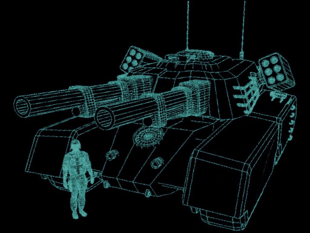
Now, while this may not mean much to anyone, it was actually original 90s artwork that was found in the game documentation itself (manual or box I think but not going all the way upstairs to check which!) which is of course bloody marvellous! Can't get much better than that fopr authenticity anyway and there's the added bonus of the image including a human presence in the foreground which provides a direct scale comparison! wicked...
So that solved part of my problem as it allowed me to use the handy blueprint line-art to determine the vertical height of the tank. I can't recall the name of the technique I used but I assumed that the soldier was of average European height and went from there. As I recall, the height from footprint to hulltop was about 6 feet or something similar. But that only gave me part of my answer as it's not possible to use this technique to effectively measure perspective lengths (accurately at least) so I looked at other methods to determine a length/width/height ratio, most of which failed! The trouble is I had so little original footage to work from. A few short low res videos, in-game sprites and fan-made images being but a few... I used all of the above but wasn't happy with the final figures. There was even a toy mammoth tank which I think I linked to before but it was by no means official and the scale and detail was atrocious...
In the end, I went for a combination of all the information I'd found and used a general average (as I must've had at least half a dozen possible 'solutions by this point!) Using an unofficial 3D model I used the OFFICIAL height of the vehicle to scale it alongside a person and an Abrahms tank (depicted in the games alongside the mammoth often) and then compared the resulting figures to what I'd learned so far. Came out huge but awesome so this was the end result...
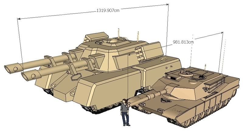
In comparison to the Abrahms 10m length, the 13m of the super heavy 90's Mammoth is actually fairly believable I think. The major difference of course is not the length but the general mass of the hull itself which almost rises above the commanders hatch of the poor little runt sat beside it! Strange though that is, she does have a 4 man crew and provisions to run a small island so I guess it makes sense and besides that's not up to me anyway as I'm being authentic!
I later came across a direct comparison between the Mammoth tank and (abrahms) medium tank which confirmed I was pretty close in the end. Here is that shot...

Now while that is all well and good I still needed more detailed plans to build the thing but I'd found these waaaaaaaay before I started the project. To do it without them would've been plain crazy! I got really lucky here with a 100% official source as I found someone had actually used the in-game 3D model of the Renegade mammoth tank to create a paper craft model. Consider it a flatpack tank... Nothgrin I have the file on my pc which I can email over to you if you let me know where to send it! I can't remember the ratio I used to bring the small model up to 1/16 scale but I believe it was 1:4.7 or something similar... The original is only a few inches across and the finished model is roughly a 27"x17" hull with another 20" in the cannon department! It has to be said, it's pretty mammoth :p
I'm now going to finish building my new workstation and will look into the new solution that's been offered up, it sounds like it certainly has some merit so I hope it'll work! Will try with one to start with and see how it goes but need the hardware first so will no doubt there will be more waiting before that happens... Nothgrin, let me have an email address and I'll send you over the plans, and if you're planning something similar please let me know as I'd love to help you if I can! The guys here have been a great help for me so far too so I'd urge you to hang around if you do try anything. Thanks and good luck! T
And here it is mocked up with the ancilliaries like the starter motor and such.
The other engine will be mounted with the gearbox rotated 180o and both will be joined with a driveshaft and differential which would allow one engine to drive a single track on each side of the vehicle if one powerplant were to fail. This prevents it being immobilised but I guess it wouldn't be going anywhere fast! The floor will be a kind of raised grating as illustrated before and the walls will be detailed with some kitbashing most likely, fuels tanks on left and right sides.
Anyway! That really is pretty much all I've done since last time I discussed this so it's time to solve the problem of these driveshafts now. I've been re-organising the house lately as the missus and I have finally decided we're better off apart which leaves me with a nice spot in the lounge for a 'Mammoth table' which I'm in the process of assembling as we speak... Hopefully walking past it everyday will encourage me to do something about it but I AM notoriously wishy washy so fingers crossed on that one...
All that stuff aside though, I have some answers for you as promised in PM Nothgrim! Thought they were better posted here as it took me quite a lot of work to actually discover this info in the first place so if I can save others the time of doing so then all the better!
So first off, the question was regarding how to scale this beast into 1:16 which I used because it's the RC tank standard of course... Documentation on fictional objects and vehicles from games and other media doesn't tend to have much of a grey area. Something is either very well documented or not documented at all. Sadly, the Mammoth tank has virtually no information available anywhere other than the images and blurb that comes from the game itself. It was featured in Command & Conquer, Command & Conquer Red Alert and Command & Conquer Generals. Although it was also in many other C & C titles, the model changed drastically and so this is the one that I needed information on.
Now remember these games go back as far as 1995 so it's not like these days when every aspect of a game is analysed and online in ten places mere hours after release. No, I remember playing this game when it was new and back in the golden nineties we actually used to just talk about this stuff... Regardless though I managed to find a handful of quotes and posthumous wikis with a little relevant information and only half of it was contradictory to itself. The largest contributor to the cause was this picture however...
Now, while this may not mean much to anyone, it was actually original 90s artwork that was found in the game documentation itself (manual or box I think but not going all the way upstairs to check which!) which is of course bloody marvellous! Can't get much better than that fopr authenticity anyway and there's the added bonus of the image including a human presence in the foreground which provides a direct scale comparison! wicked...
So that solved part of my problem as it allowed me to use the handy blueprint line-art to determine the vertical height of the tank. I can't recall the name of the technique I used but I assumed that the soldier was of average European height and went from there. As I recall, the height from footprint to hulltop was about 6 feet or something similar. But that only gave me part of my answer as it's not possible to use this technique to effectively measure perspective lengths (accurately at least) so I looked at other methods to determine a length/width/height ratio, most of which failed! The trouble is I had so little original footage to work from. A few short low res videos, in-game sprites and fan-made images being but a few... I used all of the above but wasn't happy with the final figures. There was even a toy mammoth tank which I think I linked to before but it was by no means official and the scale and detail was atrocious...
In the end, I went for a combination of all the information I'd found and used a general average (as I must've had at least half a dozen possible 'solutions by this point!) Using an unofficial 3D model I used the OFFICIAL height of the vehicle to scale it alongside a person and an Abrahms tank (depicted in the games alongside the mammoth often) and then compared the resulting figures to what I'd learned so far. Came out huge but awesome so this was the end result...
In comparison to the Abrahms 10m length, the 13m of the super heavy 90's Mammoth is actually fairly believable I think. The major difference of course is not the length but the general mass of the hull itself which almost rises above the commanders hatch of the poor little runt sat beside it! Strange though that is, she does have a 4 man crew and provisions to run a small island so I guess it makes sense and besides that's not up to me anyway as I'm being authentic!
I later came across a direct comparison between the Mammoth tank and (abrahms) medium tank which confirmed I was pretty close in the end. Here is that shot...
Now while that is all well and good I still needed more detailed plans to build the thing but I'd found these waaaaaaaay before I started the project. To do it without them would've been plain crazy! I got really lucky here with a 100% official source as I found someone had actually used the in-game 3D model of the Renegade mammoth tank to create a paper craft model. Consider it a flatpack tank... Nothgrin I have the file on my pc which I can email over to you if you let me know where to send it! I can't remember the ratio I used to bring the small model up to 1/16 scale but I believe it was 1:4.7 or something similar... The original is only a few inches across and the finished model is roughly a 27"x17" hull with another 20" in the cannon department! It has to be said, it's pretty mammoth :p
I'm now going to finish building my new workstation and will look into the new solution that's been offered up, it sounds like it certainly has some merit so I hope it'll work! Will try with one to start with and see how it goes but need the hardware first so will no doubt there will be more waiting before that happens... Nothgrin, let me have an email address and I'll send you over the plans, and if you're planning something similar please let me know as I'd love to help you if I can! The guys here have been a great help for me so far too so I'd urge you to hang around if you do try anything. Thanks and good luck! T
Re: Scratchbuilding C&Cs Mammoth Tank
Hey guys! I've been hoping to find some time for part shopping since my last post here following Nothgrin's excellent advice but sadly never got round to it... I have tonight reached tipping point though and so instead done some online bargain hunting to find suitable pipe for the suggested method. I also took a moment to re-invent the whole assembly and think I'm happier now than I ever was with it before! Here's a pic of the final plan for the drive wheels on this monstrous machine...
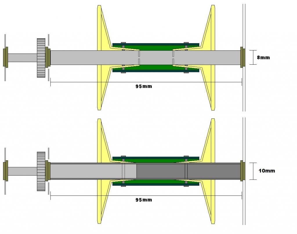
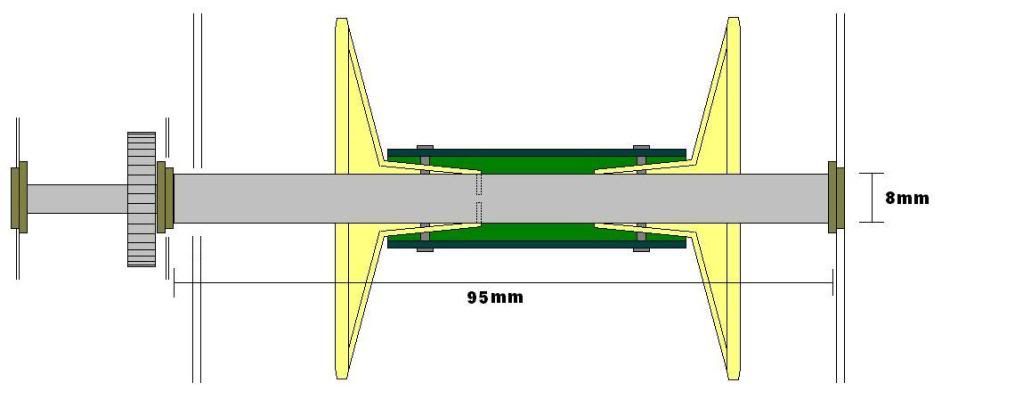
The top image is the last imagining of how the drive shaft would be constructed while at the bottom you may see a few changes.
I quickly found someone selling aluminium tube in the uk thanks to good old ebay and was ready to buy some with an 8mm outer diameter and a 1mm wall. Then I decided to check the parts first and be sure that was the best option so I got my box of goodies down from upstairs and had a revelation! The inner diameter of the sprocket faces I'll be using to construct these drive wheels is actually about 10mm leaving a 1mm air gap between it and the planned 8mm shaft. So I figured I could get some tube with an outer diameter of 10mm for a better and stronger fit and also be free of having to mess with the old shafts as a 1mm wall would be a perfect fit there too! So I now have 500mm of that stuff on it's way to me which should be more than enough for all 4 corners of the tank, and I'm a happier man for it!
The changes in the above image should reflect what's just been said. The original plan of an extended shaft is gone so the light grey now represents the shorter one I already have. The dark grey now shows where the new tube will go and all the originally planned pins remain unchanged. It may be necessary to plug the end of the new tube with some additional 8mm material for added strength but only time will tell and right now I'm confident that this design will work. If not... Well we'll see but I've spent the last year and a half barely touching this project and now I hope that time away might end here!
In addition to this purchase, I also made another buy for what will hopefully form the rear floor in the engineering bay. Below is an image I posted before showing what I was hoping it may one day look like but the kind of mesh I'd come across up to now has all been too big and therefore scales badly. Now I managed to get lucky and stumbled across some vivarium mesh with truly small holes at about 3mm long each! I'm hoping it will be just what I'm looking for but again only time will tell!

Anyway, I now have plenty to be getting on with (once ebay delivers anyway!) and I still have to build the other 3 tracks which I should probably get on with soon too. They take a long time and a lot of patience so don't want to have to do all the others at the same time, would be better to spread them out I think! Also I still have one of the engines to paint, both of them to detail and the whole engineering bay to finish once the flooring is out of the way. After that I need to reinforce the joins of the structure itself, fill and sand everywhere that needs it and apply the additional layer of armour plating that should really bring this build to life. Getting my buzz on again now I've managed to get hold of some new material so hopefully we'll be seeing a lot more of each other real soon!!!
Thanks for being there RCTW, I'd never have even attempted this build if it weren't for all the great members here! Hope you'll join me for the next step of the journey too
The top image is the last imagining of how the drive shaft would be constructed while at the bottom you may see a few changes.
I quickly found someone selling aluminium tube in the uk thanks to good old ebay and was ready to buy some with an 8mm outer diameter and a 1mm wall. Then I decided to check the parts first and be sure that was the best option so I got my box of goodies down from upstairs and had a revelation! The inner diameter of the sprocket faces I'll be using to construct these drive wheels is actually about 10mm leaving a 1mm air gap between it and the planned 8mm shaft. So I figured I could get some tube with an outer diameter of 10mm for a better and stronger fit and also be free of having to mess with the old shafts as a 1mm wall would be a perfect fit there too! So I now have 500mm of that stuff on it's way to me which should be more than enough for all 4 corners of the tank, and I'm a happier man for it!
The changes in the above image should reflect what's just been said. The original plan of an extended shaft is gone so the light grey now represents the shorter one I already have. The dark grey now shows where the new tube will go and all the originally planned pins remain unchanged. It may be necessary to plug the end of the new tube with some additional 8mm material for added strength but only time will tell and right now I'm confident that this design will work. If not... Well we'll see but I've spent the last year and a half barely touching this project and now I hope that time away might end here!
In addition to this purchase, I also made another buy for what will hopefully form the rear floor in the engineering bay. Below is an image I posted before showing what I was hoping it may one day look like but the kind of mesh I'd come across up to now has all been too big and therefore scales badly. Now I managed to get lucky and stumbled across some vivarium mesh with truly small holes at about 3mm long each! I'm hoping it will be just what I'm looking for but again only time will tell!
Anyway, I now have plenty to be getting on with (once ebay delivers anyway!) and I still have to build the other 3 tracks which I should probably get on with soon too. They take a long time and a lot of patience so don't want to have to do all the others at the same time, would be better to spread them out I think! Also I still have one of the engines to paint, both of them to detail and the whole engineering bay to finish once the flooring is out of the way. After that I need to reinforce the joins of the structure itself, fill and sand everywhere that needs it and apply the additional layer of armour plating that should really bring this build to life. Getting my buzz on again now I've managed to get hold of some new material so hopefully we'll be seeing a lot more of each other real soon!!!
Thanks for being there RCTW, I'd never have even attempted this build if it weren't for all the great members here! Hope you'll join me for the next step of the journey too
Re: Scratchbuilding C&Cs Mammoth Tank
Been working on this a LOT today and will hopefully manage a fairly sizeable update later on for anyone still interested but just having a little sit down now before I have to go and get the young'un back from school! Got a few more things to do later before I post up but see no reason why I shouldn't be able to get them done so fingers crossed you may actually see some progress later!!!
Re: Scratchbuilding C&Cs Mammoth Tank
Ok then, as promised (or threatened!) here it is! The single largest step forward this project has seen in almost 2 years and it's all thanks to Nothgrin for kickstarting my brain on the matter so thanks are in order wherever you are!
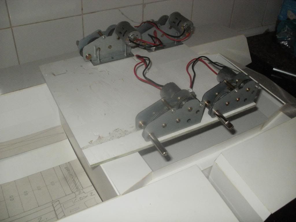
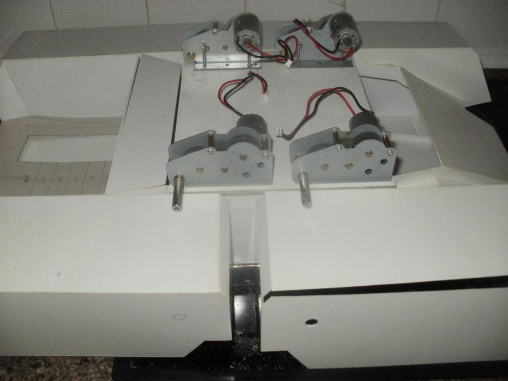
Since I finally decided how to make these gearboxes work the way I wanted them to I've been on a bit of a scavenger hunt picking up rods, wires, grills, bolts, tools, drills and even a broken road sign in order to prepare for the day when I would actually find the time to put my plans into action. I managed to get all of the pieces cut for my second track about a week ago but only actually assembled half of it so don't have much to show on that front yet. EVerything I DID get doen on it was done in about half a day though which is a massive improvement on the first 'prototype' track so that bodes well for the future of this build. Also let's be honest, once you've seen one track the other three are quite probably going to be fairly similar! Here's a snap I took of the component parts for track no.2 just for the hell of it though...

So onto the real progress which has been spread over yesterday and today, mostly today as when I turned in for the night yesterday I was somewhat despairing at how on earth I was going to fit all of this track gubbins into the given dimensions of the tank itself. This morning however I was hit with a few decent Eureka moments and decided that all the stuff I wasn't 100% on would probably sort itself out as I went along... Or at least I probably wouldn't have to worry about it for another 2 years!
Apologies for what follows as the bulk of the pictures I took don't seem to be in any particular order (even though they are!) but I'll try and piece together some sort of narrative for what's been going on here for the last 48 hours if I can. That said, there are enough pictures to make it fairly clear anyway so here it is!
One of the jobs I've needed to address for some time was how to actully mount the 4 gearboxes in this build and after many redesigns I finally came up with an idea I was happy with. I already knew they would be mounted upside-down due to the shape and size of the tank itself so the trick was always going to be how to have them suspended from the top of the hull. Also I want this to remain accessible once it's finished or every time I need to tinker with it I'll need to physically dismantle parts of the finished model and that would suck...
There are no WIP pics of the first design of this gearbox assembly but it's fairly self explanatory... Small bolts were removed from the gearbox bases and then after many hours of measuring they were all fixed to the four corners of the stolen road sign I mean salvaged of course... As with all of my various projects I try to reuse as much material as possible, partly because I'm poor but mostly because I'm broke.
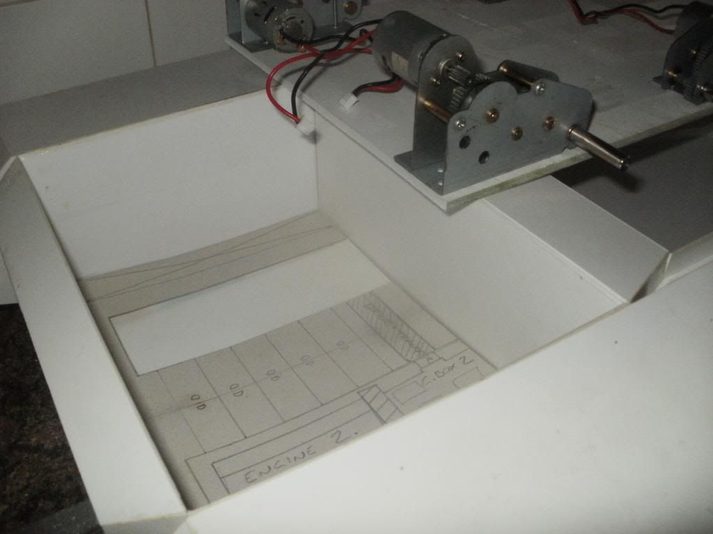
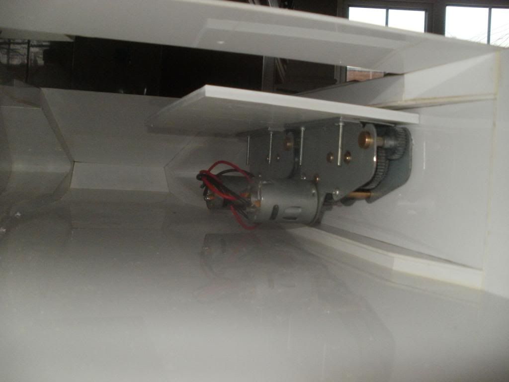
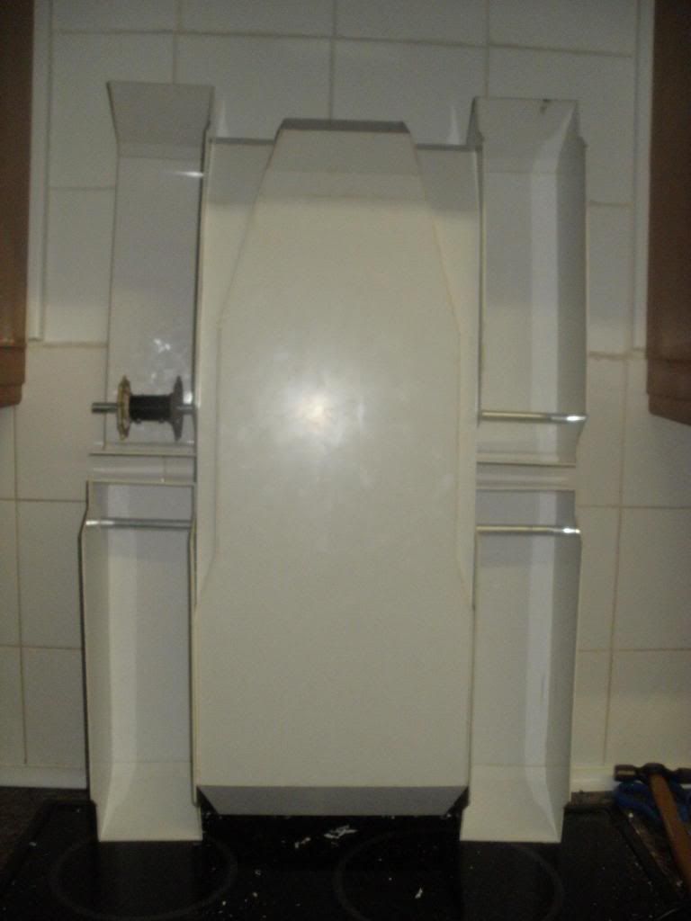
The next image shows the first problem with this supposedly 'final' design... Given that I'm keeping the rear portion of this build as a sort of engine room 'diorama' it would be a bit of a pain to have the back-ends of two massive gearboxes sticking through the wall. Sadly you can see in this picture that that's exactly what's going on here...
Also, just because this is when I took the picture, it was at this point I spent a great deal of time trying to determine where the holes would need to be cut in the model for each of the four axles (which we'll get to later!) I ended up having to remove and reattach two of the four track housings in the end due to incorrect angle and positioning which is why one of them here is partially dismantled and how I managed to drill through just one of the two layers of plastic there!
BAck to the gearboxes, it was actually a very easy fix once I stood looking at it for a second. It's often very hard to visualise thing until they're actually there in front of you and this was one of those moments. While I had previously thought the space between the gearboxes on each side would be very small it turned out to be huge and so thankfully I managed to save the engine room very easily indeed! Here it is again after a quick switcheroo...
And as I want these boxes to be removable once the whole project is over I obviously had to chop off the extra overhang. It all worked out much better than I ever could've hoped in the end as the original design would've been practically impossible to work on and required frequent dismantling even while I continued to build it! Here is the final (but not finished) gearbox tray.
Popping out of picture order quickly, I may as well finish of with this tray before moving onto the axles so here comes that bit... The observant among you may notice that all previous pictures of this tray have been upside down with respect to it's final location in the tank. That's because it'd be impossible for me to fit the tray like that on account of the driveshafts sticking out of it's sides! The original plan was going to be a fixed tray with an access hole in the centre which would allow for individual box removal by removing their respective bolts. I came up with something I'm much happier with though and I'm hoping it'll be adaptable enough to evolve along with the tank itself when more hardware is added later on.
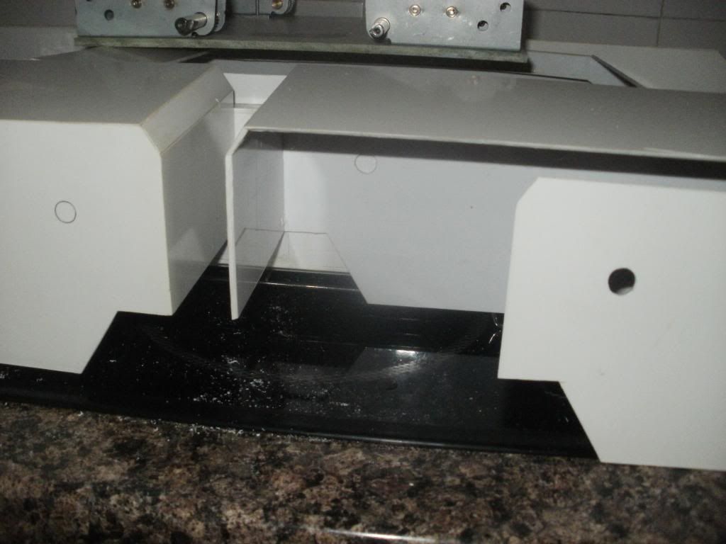
The solution is this, the board has simply been chopped in half...
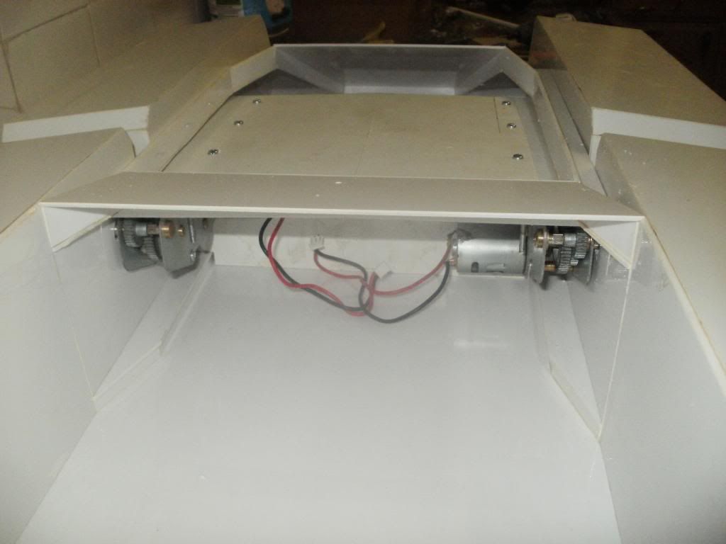
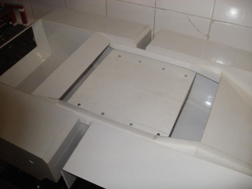
Later it recieved the addition of a central support to prevent sagging and aid in general stability. This will be a permanent fixture in the hull and will add significant strength in several ways and places. Here's a shot showing both sides fitted as well as the central support, though obviously only 2 gearboxes are now visible...
Clearly for that last shot to have been successful, all of the axles holes must by now have been cut in the hull sides and as you may have spotted also in the outermost sides of the tank beyond the tracks. This is due to the size and weight of both the tracks and the tank in general, the axles will run from the gearbox, through the tracks and ultimately to bushes in the track housings. For now I've simply cut the axles too long and left an overhang but of course they won't stay that way...
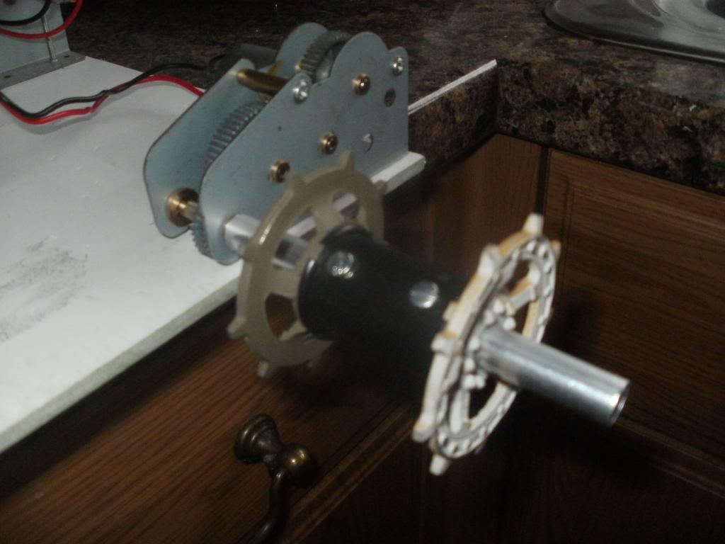
The axles themselves are simply 105mm sections of metal rod which slip around the final driveshaft of the gearboxes I'm using, this was shown in the last image of my previous post. And for those of you that had trouble envisioning how that whole assembly was going to work, here it is!
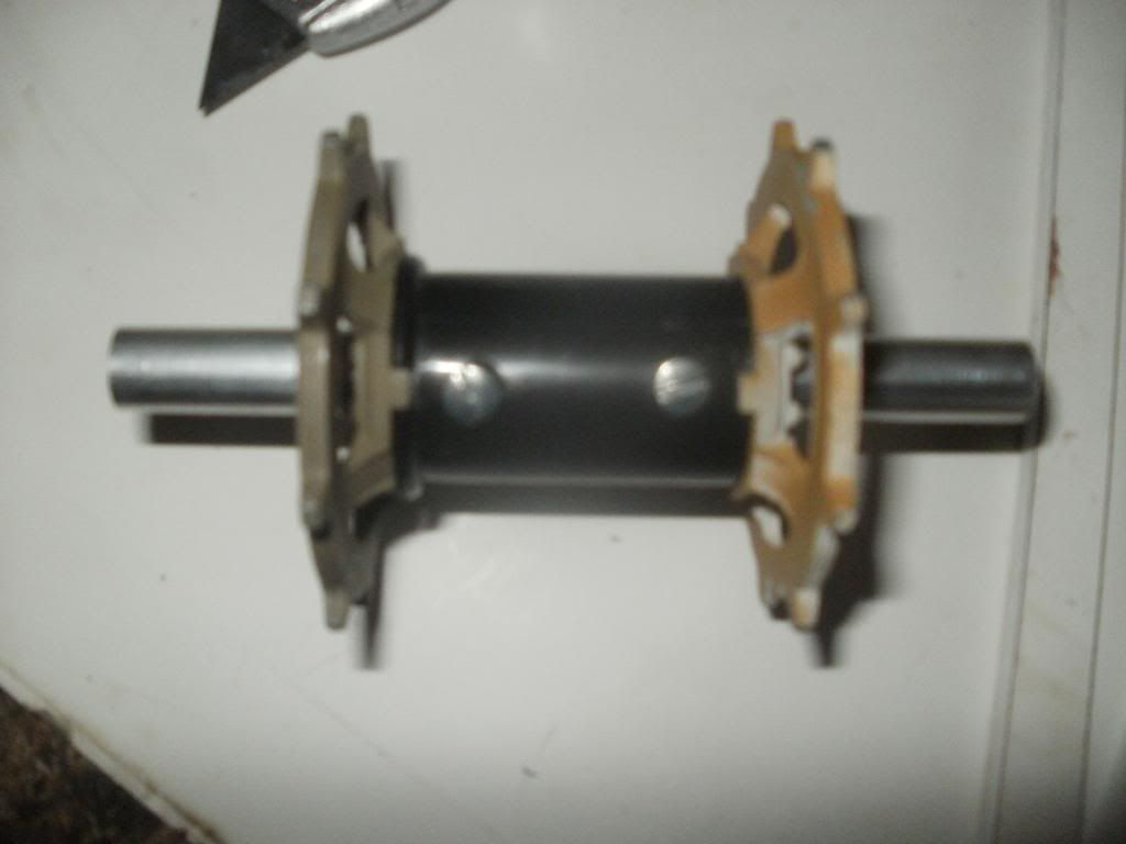
And yes I realise that is an awful picture... But you get the idea hopefully, it's simply the axle at the centre, drive wheels drilled out to 10mm and slid onto that, a plastic tube used for a spacer and then two bolts right through everything to keep it locked tight together. It wasn't actually too hard to make in the end, though I did almost lose a thumb trying to drill out the centre of the first drive wheel. Needless to say I'll be finding a better way to do that for the next ones as I've only finished the one so far!
My original hope was that one of those two bolts would also pass through the driveshaft and lock the two pieces together but sadly that isn't going to be the case due to the shaft being too short to reach the bolts! That simply means I'll need to place a third bolt through just the driveshaft and axle at a later date but it does mean future disassembly will be that much easier so it's another silver lined cloud. Here is how it looks on the gearbox that'll run it.
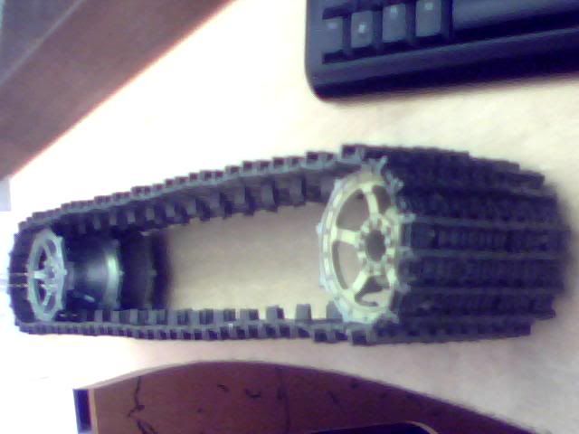
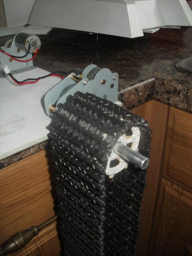
And here it is with the track it'll drive too!
I was pretty damn chuffed when all this stuff started coming together so forgive me for the unnecessary quantity of images. I'm just very happy that things are starting to happen again!
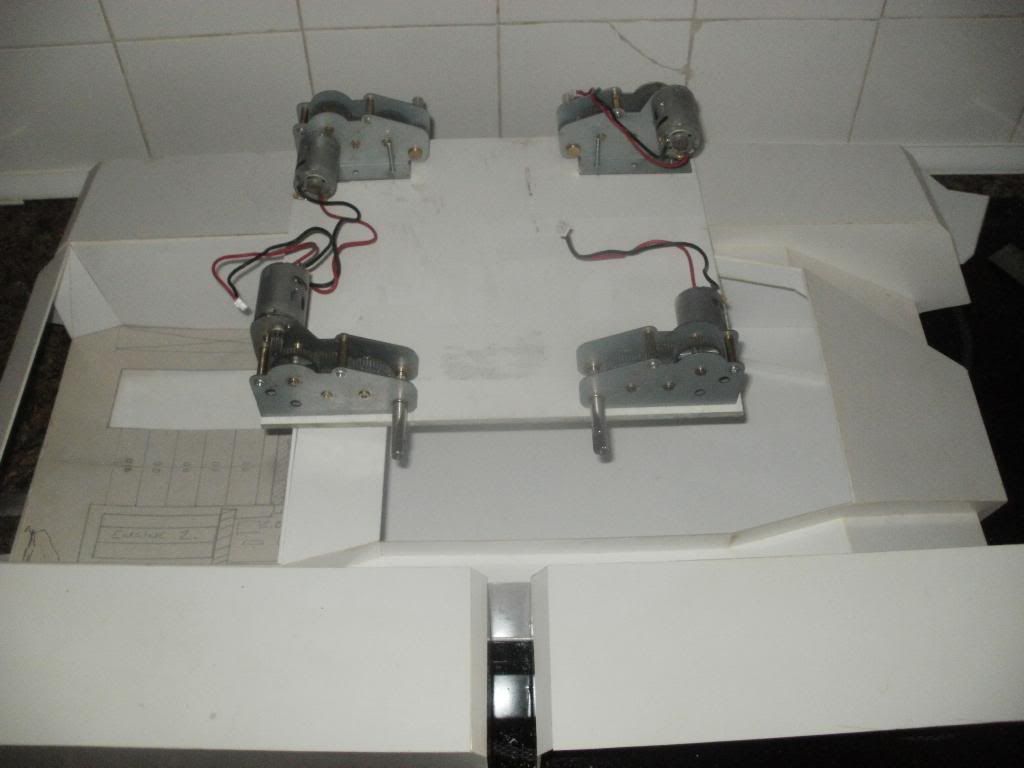
Anyway, although it's taken most of today that's pretty much all I have to show. Most of my time has been spent measuring, remeasuring, measuring one more time and then wondering why it's still wrong after measuring so many times... Needless to say there have been many alterations made over the course of the day but it's all worked out pretty damn well as far as I'm concerned! Here are some final pictures showing all the gearboxes fitted and the axles in place, though only one of them is a finished drivewheel so far... Nothing in this picture is mocked up for a nice change, it's actually really in there the way it should be!
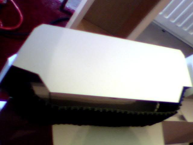
And here because I have a picture of it is all that's visible in the top of the build right now. Those gearboxes are totally solid and I've no reason to suspect they'll be going anywhere any time soon!
Also a pic I missed out of how the drive wheel is going to operate. This is a fair bit earlier in the day but it gives you an idea of what's going on in there mechanically speaking...

And finally, I'm back to mock-ups now trying to figure out if I can have the other wheels suspended of not. Also working to position the bogeys and any other rollers and tensioners I may need. The hard work in this area is still far from over but I at least feel now like the biggest step has been taken.
Notice how close those two sprockets are at the back? I'm pretty sure at least that one will have to remain unsprung but frankly I'm all for simplicity in a build that I'm already so concerned about. There's only so many things I can do to reinforce this and I'm by no means 'good' at what I'm doing here so it may be wise to avoid suspended wheels completely for now and just stick a tensioner in there to keep things going smoothly. We'll see as I progress but if there's any advice out there I'd love to hear it.
Going to need to move onto reinforcement soon as I don't want to get too carried away with the track mechanism until I have at least SOME colour on this thing or I'll be forever dismantling and rebuilding it! I figure I could maybe just get away with blacking up the under armour parts for now but we'll see. I want to fill all of the internal joins to add some strength to the shell first anyway and I'm also going to add some bolts to hold the four track housings to the hull itself. Having to take them off today made me realise just how well built this is but it's still a bit patchy so especially in these weakpoints I'm going to need more strength.
The next job for now is to finish those other 3 drive axles and then I'll have a tidy up and get reorganised before biting off the next job, though I'll need to finish track no.2 soon... I also have all the material I need to begin detailing the engine room which will be a fun distraction and very different kind of modelling but I'm away now tomorrow so it'll have to wait a few days.
I'll update again when I either run out of jobs to do or have something exciting to share. Not sure when either of those things will happen butplease let me know what you think of the progress and keep watching!
T
Since I finally decided how to make these gearboxes work the way I wanted them to I've been on a bit of a scavenger hunt picking up rods, wires, grills, bolts, tools, drills and even a broken road sign in order to prepare for the day when I would actually find the time to put my plans into action. I managed to get all of the pieces cut for my second track about a week ago but only actually assembled half of it so don't have much to show on that front yet. EVerything I DID get doen on it was done in about half a day though which is a massive improvement on the first 'prototype' track so that bodes well for the future of this build. Also let's be honest, once you've seen one track the other three are quite probably going to be fairly similar! Here's a snap I took of the component parts for track no.2 just for the hell of it though...
So onto the real progress which has been spread over yesterday and today, mostly today as when I turned in for the night yesterday I was somewhat despairing at how on earth I was going to fit all of this track gubbins into the given dimensions of the tank itself. This morning however I was hit with a few decent Eureka moments and decided that all the stuff I wasn't 100% on would probably sort itself out as I went along... Or at least I probably wouldn't have to worry about it for another 2 years!
Apologies for what follows as the bulk of the pictures I took don't seem to be in any particular order (even though they are!) but I'll try and piece together some sort of narrative for what's been going on here for the last 48 hours if I can. That said, there are enough pictures to make it fairly clear anyway so here it is!
One of the jobs I've needed to address for some time was how to actully mount the 4 gearboxes in this build and after many redesigns I finally came up with an idea I was happy with. I already knew they would be mounted upside-down due to the shape and size of the tank itself so the trick was always going to be how to have them suspended from the top of the hull. Also I want this to remain accessible once it's finished or every time I need to tinker with it I'll need to physically dismantle parts of the finished model and that would suck...
There are no WIP pics of the first design of this gearbox assembly but it's fairly self explanatory... Small bolts were removed from the gearbox bases and then after many hours of measuring they were all fixed to the four corners of the stolen road sign I mean salvaged of course... As with all of my various projects I try to reuse as much material as possible, partly because I'm poor but mostly because I'm broke.
The next image shows the first problem with this supposedly 'final' design... Given that I'm keeping the rear portion of this build as a sort of engine room 'diorama' it would be a bit of a pain to have the back-ends of two massive gearboxes sticking through the wall. Sadly you can see in this picture that that's exactly what's going on here...
Also, just because this is when I took the picture, it was at this point I spent a great deal of time trying to determine where the holes would need to be cut in the model for each of the four axles (which we'll get to later!) I ended up having to remove and reattach two of the four track housings in the end due to incorrect angle and positioning which is why one of them here is partially dismantled and how I managed to drill through just one of the two layers of plastic there!
BAck to the gearboxes, it was actually a very easy fix once I stood looking at it for a second. It's often very hard to visualise thing until they're actually there in front of you and this was one of those moments. While I had previously thought the space between the gearboxes on each side would be very small it turned out to be huge and so thankfully I managed to save the engine room very easily indeed! Here it is again after a quick switcheroo...
And as I want these boxes to be removable once the whole project is over I obviously had to chop off the extra overhang. It all worked out much better than I ever could've hoped in the end as the original design would've been practically impossible to work on and required frequent dismantling even while I continued to build it! Here is the final (but not finished) gearbox tray.
Popping out of picture order quickly, I may as well finish of with this tray before moving onto the axles so here comes that bit... The observant among you may notice that all previous pictures of this tray have been upside down with respect to it's final location in the tank. That's because it'd be impossible for me to fit the tray like that on account of the driveshafts sticking out of it's sides! The original plan was going to be a fixed tray with an access hole in the centre which would allow for individual box removal by removing their respective bolts. I came up with something I'm much happier with though and I'm hoping it'll be adaptable enough to evolve along with the tank itself when more hardware is added later on.
The solution is this, the board has simply been chopped in half...
Later it recieved the addition of a central support to prevent sagging and aid in general stability. This will be a permanent fixture in the hull and will add significant strength in several ways and places. Here's a shot showing both sides fitted as well as the central support, though obviously only 2 gearboxes are now visible...
Clearly for that last shot to have been successful, all of the axles holes must by now have been cut in the hull sides and as you may have spotted also in the outermost sides of the tank beyond the tracks. This is due to the size and weight of both the tracks and the tank in general, the axles will run from the gearbox, through the tracks and ultimately to bushes in the track housings. For now I've simply cut the axles too long and left an overhang but of course they won't stay that way...
The axles themselves are simply 105mm sections of metal rod which slip around the final driveshaft of the gearboxes I'm using, this was shown in the last image of my previous post. And for those of you that had trouble envisioning how that whole assembly was going to work, here it is!
And yes I realise that is an awful picture... But you get the idea hopefully, it's simply the axle at the centre, drive wheels drilled out to 10mm and slid onto that, a plastic tube used for a spacer and then two bolts right through everything to keep it locked tight together. It wasn't actually too hard to make in the end, though I did almost lose a thumb trying to drill out the centre of the first drive wheel. Needless to say I'll be finding a better way to do that for the next ones as I've only finished the one so far!
My original hope was that one of those two bolts would also pass through the driveshaft and lock the two pieces together but sadly that isn't going to be the case due to the shaft being too short to reach the bolts! That simply means I'll need to place a third bolt through just the driveshaft and axle at a later date but it does mean future disassembly will be that much easier so it's another silver lined cloud. Here is how it looks on the gearbox that'll run it.
And here it is with the track it'll drive too!
I was pretty damn chuffed when all this stuff started coming together so forgive me for the unnecessary quantity of images. I'm just very happy that things are starting to happen again!
Anyway, although it's taken most of today that's pretty much all I have to show. Most of my time has been spent measuring, remeasuring, measuring one more time and then wondering why it's still wrong after measuring so many times... Needless to say there have been many alterations made over the course of the day but it's all worked out pretty damn well as far as I'm concerned! Here are some final pictures showing all the gearboxes fitted and the axles in place, though only one of them is a finished drivewheel so far... Nothing in this picture is mocked up for a nice change, it's actually really in there the way it should be!
And here because I have a picture of it is all that's visible in the top of the build right now. Those gearboxes are totally solid and I've no reason to suspect they'll be going anywhere any time soon!
Also a pic I missed out of how the drive wheel is going to operate. This is a fair bit earlier in the day but it gives you an idea of what's going on in there mechanically speaking...
And finally, I'm back to mock-ups now trying to figure out if I can have the other wheels suspended of not. Also working to position the bogeys and any other rollers and tensioners I may need. The hard work in this area is still far from over but I at least feel now like the biggest step has been taken.
Notice how close those two sprockets are at the back? I'm pretty sure at least that one will have to remain unsprung but frankly I'm all for simplicity in a build that I'm already so concerned about. There's only so many things I can do to reinforce this and I'm by no means 'good' at what I'm doing here so it may be wise to avoid suspended wheels completely for now and just stick a tensioner in there to keep things going smoothly. We'll see as I progress but if there's any advice out there I'd love to hear it.
Going to need to move onto reinforcement soon as I don't want to get too carried away with the track mechanism until I have at least SOME colour on this thing or I'll be forever dismantling and rebuilding it! I figure I could maybe just get away with blacking up the under armour parts for now but we'll see. I want to fill all of the internal joins to add some strength to the shell first anyway and I'm also going to add some bolts to hold the four track housings to the hull itself. Having to take them off today made me realise just how well built this is but it's still a bit patchy so especially in these weakpoints I'm going to need more strength.
The next job for now is to finish those other 3 drive axles and then I'll have a tidy up and get reorganised before biting off the next job, though I'll need to finish track no.2 soon... I also have all the material I need to begin detailing the engine room which will be a fun distraction and very different kind of modelling but I'm away now tomorrow so it'll have to wait a few days.
I'll update again when I either run out of jobs to do or have something exciting to share. Not sure when either of those things will happen butplease let me know what you think of the progress and keep watching!
T
-
blimp

- Sergeant
- Posts: 739
- Joined: Sat Dec 11, 2010 12:29 am
- Location: Watford , NW Londonistan . U.K.
Re: Scratchbuilding C&Cs Mammoth Tank
Yo Munty , long time no see ! It's looking good mate . - About the hull reinforcement , how about 'L' section styrene strip or wooden beading for the inner corners ? ( The first option will use less room , the second is cheapness / availability ) . . . Oh , and for your gun barrels - have a nosey down your local fishing tackle emporium , look for carbon fibre rod sections , the larger diameter ones should be ideal . Light , strong and cheap . I recently picked up a shop soiled one for nowt , and a new 'un for £2.00 ( for a scratch build of my own ) anyway , good to see you back on the case !
to the bouncy room ! Yay !
Re: Scratchbuilding C&Cs Mammoth Tank
Hey blimp, it's good to be back! Only time will tell how long I'm here for this time but I'm trying to diversify my goals right now to give me a better chance of achieving something before I inevitably wander again... I've been working on the detailing in the engineering bay and it's looking good but very plain with nothing on the walls Need to find a good material for fuel tanks and then try a bit of kit-bashing for the back wall! Also need to get the reinforcement done which is the reason for my sudden reappearance (as well you know!) and I have 2 more tracks to build as well as the remaining 3 driveshafts which I'm nervous about as the first one nearly cost me a finger... On top of all that I'd REALLY like to see the turret looking more like a turret and I'm happy to put it together without any tech for now to achieve that. I'm currently building the 'mammoths tusk' rocket pods which mount on it (they hold six StA missiles each because why the hell not...) On the prowl again for barrels too obviously and will check out the fishing shop as that's a sterling idea! Got some piccies of detailing I've done this week but not enough to share yet so will keep them till I've achieved a little more. As it is got plenty to do for now! Off to town for fishing rods and styrene lol (note - rods not poles, poles are for flags, rods are for fishing) A thought does occur though that angled styrene won't be able to handle the non-90o corners... I really wish someone could give me a product name for some sort of tape reinforcement thingumajig!
