Scratchbuilding C&Cs Mammoth Tank
Re: Scratchbuilding C&Cs Mammoth Tank
Thanks Blimp, it it! Slowly but surely It's moving from an idea to something I can actually see in front of me. It's a good feeling 
Anyway, thought I'd post up a few of my trademark crap pictures of the gearbox assembly I've been working on. I'm being careful to take my time about it so it's coming along pretty nicely but it's still fairly basic (with only minor highlights applied right now) These pics mostly serve to show what I've modified in order to allow the model in question to suit my purposes but also act as a nice visual aid for anyone who can advise me on further paint and detail effects.
So here it comes anyway, enjoy and comment freely as always!
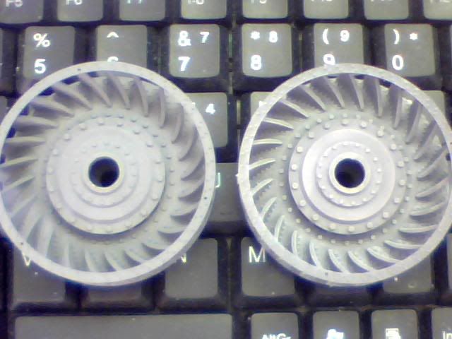
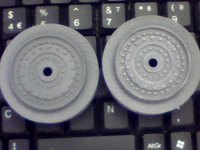
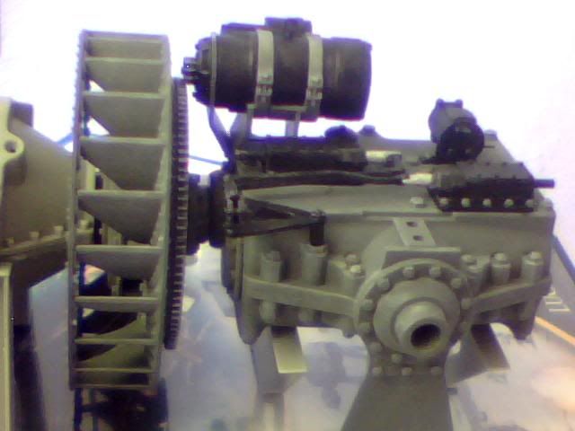
I mentioned in my last post that I'd started on the flywheels and here they are in their component parts (a fourth piece is just out of shot) Both have been sprayed with a tin of humbrol paint I happened to have but only the top parts have had the highlights added with a lighter grey drybrushing.
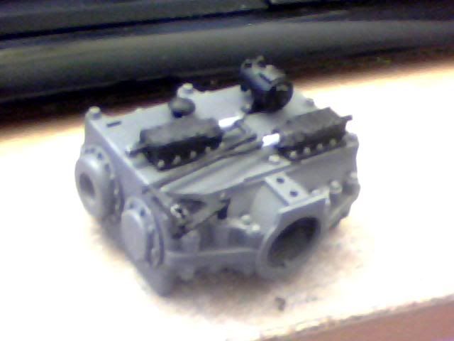
Next it was onto the gearbox which I also sprayed with the dark grey. I have a Citadel paint (Games Workshop stuff) which is a near perfect match for the dark humbrol stuff which I've been using to touch up the spray job and finish off small pieces. I prefer using that to the actual humbrol one as it means I only need water to clean my brush and as I'm only using each colour for a few minutes at a time it saves a lot of time! Anyway, I drybrushed the box with the light grey then painted the covers on top of it black to correspond with the painted components they would mount. In order to add a little more detail and maintain as much realism as possible I repainted the securing studs and nuts back to the original colour of the box.
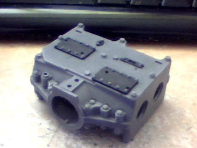
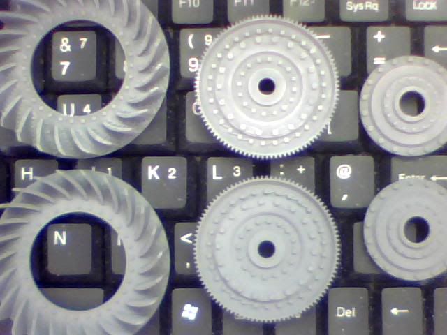
At this point the box is completely standard but actually I've already modified the other end of it. This is where the drive will be transferred from the engine and flywheel to the gearboxes input shaft. Originally there are 2 holes in each end of this assembly as seen in the previous image. These fit the left-hand part in the following image and accomodate the brakes on either side of the gearbox in the standard kit.
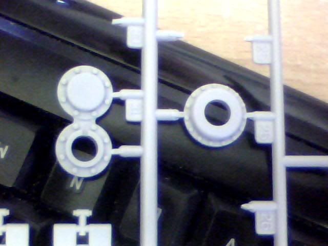
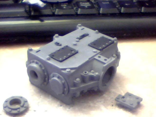
I initially planned to cover both of these holes and then use some other parts to create a single input for the box but that left me without any really useful parts for elsewhere. Instead I took that first part on the left of the above picture and cut it in half. Then I took the larger part from the right side of the same image and used that to replace the part I cut away. In order for both parts to fit how I wanted, the right hand hole in the box was enlarged by cutting away some plastic there. The reason I didn't just use the original piece will become apparent later but basically it's due to getting the starter motor lined up right... Here it is anyway with the slight modification in place. The unused offcut is to the left and to the right is the mount for the starter motor which fits in the two holes right near it when constructed normally. It's no good to me though as it will place the starter too high if used in my setup...
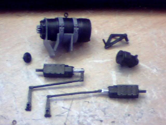
Speaking of the starter motor, here it is! Along with it are what I presume are gear selectors and other little odds and sods from the top of the assembly. I originally painted the whole starter motor grey but later realised that everything was the same colour and this seemed like a good thing to change. I kept the brackets and straps in the same grey as the rest of the box while making the motor itself flat black (as most are anyway) I added some silver to the linkages (on the moving piston) and to the teeth on both the starter and the flywheel.
Here's the semi-finished assembly without the starter motor (none of the top parts are glued on though)
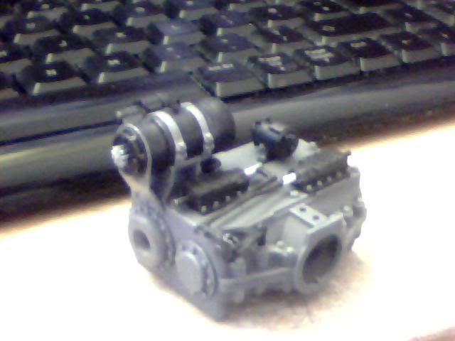
And here it is with the starter motor in it's usual place as if I were building the Trumpeter kit it came from. Note the small mount I mentioned earlier.
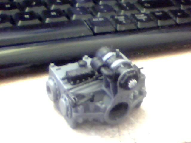
Here's the starter motor as it will be positioned in my layout. The extra protrusion of the new input cover I've used (about 1.5mm) permits the teeth on the motor to sit perfectly where they should do (NOT engaged with the flywheel for those who don't know their mechanics) By omitting the mount for the starter and snipping off the locating lugs from the bottom of it's brackets it also happens to be at the perfect height relative for the flywheel too so I got pretty lucky here! It even sits perfectly in the space between that linkage and the edge of the entire assembly so it looks almost like it was made for the job! Oh and it's centrally located above the input shaft too which isn't technically necessary but looks good so I'm happy with that
Welcome to picture 200!
Remember, when I do the other gearbox everything will be symmetrically arranged (as much as possible at any rate) The linkages may have to remain in their intended positions but that's to be expected as in real life there would be no need to manufacture 2 completely different gearboxes for this tank. It would simply be reversible to allow for internal adjustments to change gearing and allow input and output to be swapped. That means the external components could still be mounted identically to the opposing side of the tank. The starter motor of course doesn't follow this rule but meh...
So here are a few parting glamour shots of what this looks like now. It should also give a vague idea of what it will look like when completely finished but of course the engine is untouched right now...

Anyway, thought I'd post up a few of my trademark crap pictures of the gearbox assembly I've been working on. I'm being careful to take my time about it so it's coming along pretty nicely but it's still fairly basic (with only minor highlights applied right now) These pics mostly serve to show what I've modified in order to allow the model in question to suit my purposes but also act as a nice visual aid for anyone who can advise me on further paint and detail effects.
So here it comes anyway, enjoy and comment freely as always!
I mentioned in my last post that I'd started on the flywheels and here they are in their component parts (a fourth piece is just out of shot) Both have been sprayed with a tin of humbrol paint I happened to have but only the top parts have had the highlights added with a lighter grey drybrushing.
Next it was onto the gearbox which I also sprayed with the dark grey. I have a Citadel paint (Games Workshop stuff) which is a near perfect match for the dark humbrol stuff which I've been using to touch up the spray job and finish off small pieces. I prefer using that to the actual humbrol one as it means I only need water to clean my brush and as I'm only using each colour for a few minutes at a time it saves a lot of time! Anyway, I drybrushed the box with the light grey then painted the covers on top of it black to correspond with the painted components they would mount. In order to add a little more detail and maintain as much realism as possible I repainted the securing studs and nuts back to the original colour of the box.
At this point the box is completely standard but actually I've already modified the other end of it. This is where the drive will be transferred from the engine and flywheel to the gearboxes input shaft. Originally there are 2 holes in each end of this assembly as seen in the previous image. These fit the left-hand part in the following image and accomodate the brakes on either side of the gearbox in the standard kit.
I initially planned to cover both of these holes and then use some other parts to create a single input for the box but that left me without any really useful parts for elsewhere. Instead I took that first part on the left of the above picture and cut it in half. Then I took the larger part from the right side of the same image and used that to replace the part I cut away. In order for both parts to fit how I wanted, the right hand hole in the box was enlarged by cutting away some plastic there. The reason I didn't just use the original piece will become apparent later but basically it's due to getting the starter motor lined up right... Here it is anyway with the slight modification in place. The unused offcut is to the left and to the right is the mount for the starter motor which fits in the two holes right near it when constructed normally. It's no good to me though as it will place the starter too high if used in my setup...
Speaking of the starter motor, here it is! Along with it are what I presume are gear selectors and other little odds and sods from the top of the assembly. I originally painted the whole starter motor grey but later realised that everything was the same colour and this seemed like a good thing to change. I kept the brackets and straps in the same grey as the rest of the box while making the motor itself flat black (as most are anyway) I added some silver to the linkages (on the moving piston) and to the teeth on both the starter and the flywheel.
Here's the semi-finished assembly without the starter motor (none of the top parts are glued on though)
And here it is with the starter motor in it's usual place as if I were building the Trumpeter kit it came from. Note the small mount I mentioned earlier.
Here's the starter motor as it will be positioned in my layout. The extra protrusion of the new input cover I've used (about 1.5mm) permits the teeth on the motor to sit perfectly where they should do (NOT engaged with the flywheel for those who don't know their mechanics
Welcome to picture 200!
Remember, when I do the other gearbox everything will be symmetrically arranged (as much as possible at any rate) The linkages may have to remain in their intended positions but that's to be expected as in real life there would be no need to manufacture 2 completely different gearboxes for this tank. It would simply be reversible to allow for internal adjustments to change gearing and allow input and output to be swapped. That means the external components could still be mounted identically to the opposing side of the tank. The starter motor of course doesn't follow this rule but meh...
So here are a few parting glamour shots of what this looks like now. It should also give a vague idea of what it will look like when completely finished but of course the engine is untouched right now...
Re: Scratchbuilding C&Cs Mammoth Tank
What a great job you're doing of this, Munty. I love the way you've re-arranged the transmission boxes and starters to fit the setup you're making. Looks like they were meant to be that way! Oh, and I also wanted to say that your cardboard mockup of the engine room floor was very impressive as well. Never thought about mocking up an area before - I usually just dive in and try to fit things wherever I can, as I go along. Your way makes a LOT more sense, and I will use it in the future. Thnak you for sharing your tips. -Mike
-
blimp

- Sergeant
- Posts: 739
- Joined: Sat Dec 11, 2010 12:29 am
- Location: Watford , NW Londonistan . U.K.
Re: Scratchbuilding C&Cs Mammoth Tank

to the bouncy room ! Yay !
Re: Scratchbuilding C&Cs Mammoth Tank
Thanks guys! Welcome back Mike, glad you like what I'm doing with your engines I find mocking up stuff first always helps, hence the first thing I did on receiving the parts was to set up a few parts to get some accurate measurements. The overall layout also helps me figure out how much of various materials I'm going to need, like the flooring I'm still searching for! Really the main purpose of the mockup in this case was to figure out how to detail the area as a whole though. With known measurements of the engines and such, and a predetermined gap in the centre for the engineer, it showed me exactly how much other space I have to fill before I move onto fastening anything down. I've been following the same kind of practice with the gearbox to be honest as I'm altering it (albeit very slightly) as I go.
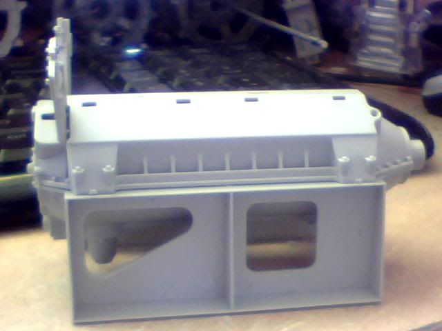
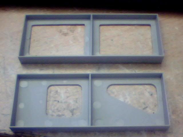
Anyway, moving on! I haven't progressed any further since taking those last pictures except I put down the first bit of colour so far! As you can see from the above images, the engine mounts look very weird shapes and it's clear that they're intended not to be seen in the completed Trumpeter kit. I'm planning to use them for my build though so I cut out the central shapes to make them nice neat squares. It looks a LOT better but sadly there are quite a few raised marks left from the injection moulding. It's fair enough as noone should ever see this part but it's a bit of a bummer for me. That said though, most of what I'm doing in the engineering bay will be practically invisible most of the time so it's no drama really I guess! I still haven't decided how to allow better visibility to be honest but I'm thinking replacing the chequerplate on the top of the hull with grills I can open would be a good move. That way they'd serve the logical function of aiding engine removal. The only trouble is that it would require turret removal for them to be accessed (even in the model) so I dunno yet...
Those newly cut engine mounts though, and the gearbox mounts (which I'll be using sideways and upside down in the final build) have all been painted with the closest colour I have to the GDI desert paintscheme (which is the only one the Mammoth tank is ever seen in) My current colour is actually one I use for decking my warships (Humbrol 63) and it's quite off what I really need but for now it's fine. Here's a shot that is about right colour wise...

Mine is way too orangey right now but as I say it can be fixed later... I think I'll have the internal walls of the engineering bay as well as the true hull bottom (which will be visible through the grating) painted in this colour. It'll give a contrast to all the grey and other metal colours present without looking over the top. Or at least I think it will!
Think I may start on the engine today but my son is being very needy so I may have a hard time to be honest! Blimp thanks for the sketch man, I appreciate you taking the time to help me out as always I wonder if a single setup split two ways might be lacking in power to move something this big though, what do you think? With just the shell finished it's already getting fairly heavy and that's without any of the hardware in it. Fact of the matter is it'll far outweigh any similar RC model out there just based on size alone. Good news is I think I've found some metal that I can use to get on with making some new tracks though so I should be able to start testing some of these ideas out soon! Though I need driveshafts first and either way they'll need to be custom made
Anyway, moving on! I haven't progressed any further since taking those last pictures except I put down the first bit of colour so far! As you can see from the above images, the engine mounts look very weird shapes and it's clear that they're intended not to be seen in the completed Trumpeter kit. I'm planning to use them for my build though so I cut out the central shapes to make them nice neat squares. It looks a LOT better but sadly there are quite a few raised marks left from the injection moulding. It's fair enough as noone should ever see this part but it's a bit of a bummer for me. That said though, most of what I'm doing in the engineering bay will be practically invisible most of the time so it's no drama really I guess! I still haven't decided how to allow better visibility to be honest but I'm thinking replacing the chequerplate on the top of the hull with grills I can open would be a good move. That way they'd serve the logical function of aiding engine removal. The only trouble is that it would require turret removal for them to be accessed (even in the model) so I dunno yet...
Those newly cut engine mounts though, and the gearbox mounts (which I'll be using sideways and upside down in the final build) have all been painted with the closest colour I have to the GDI desert paintscheme (which is the only one the Mammoth tank is ever seen in) My current colour is actually one I use for decking my warships (Humbrol 63) and it's quite off what I really need but for now it's fine. Here's a shot that is about right colour wise...
Mine is way too orangey right now but as I say it can be fixed later... I think I'll have the internal walls of the engineering bay as well as the true hull bottom (which will be visible through the grating) painted in this colour. It'll give a contrast to all the grey and other metal colours present without looking over the top. Or at least I think it will!
Think I may start on the engine today but my son is being very needy so I may have a hard time to be honest! Blimp thanks for the sketch man, I appreciate you taking the time to help me out as always
Re: Scratchbuilding C&Cs Mammoth Tank
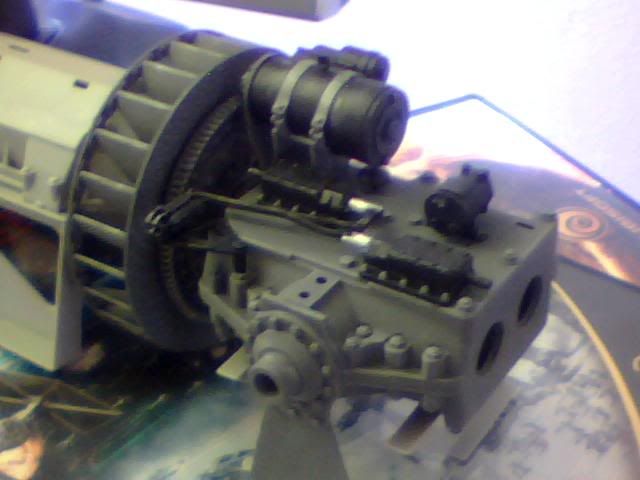
I wanted to get a feel for how the whole engine and drivetrain would look today so I sprayed up one of the engine sprues in the dark grey to form me a base. I've now assembled a lot more of it than I had previously (cylinder heads and fuel pump too now) and it's actually much taller than I'd thought which is a good thing. It becomes immediately obvious that keeping everything the same tone of grey will look crap so I'm now in the process of trawling the interweb for images of how these engines look in the T34s they were made for. First off here's what it looks like mocked up in the flat grey (not even got highlights here yet)
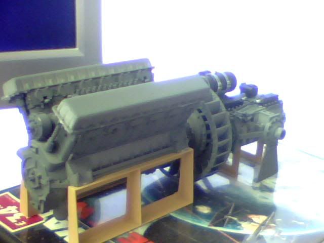
Note the altered engine mounts which now add a little colour to this dreary assembly. Here's a quick pic of what they used to look like, clearly no good for the prominent positions they'll be taking in my tank...
And here's the difference between the old and new brackets. I figure it's a simple construction made of angled metal. The engineer needs access to as much of the engine as possible after all so can't have big slabs blocking the sides...
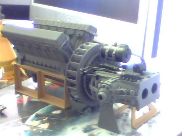
Anyway back to what shall be called 'colour diversity' A lot of images I've found so far show T34s with red valve and rocker covers so there's a possibility to add some variation there but I don't want red... I wondered if maybe I could use the same colour as the hull and such (the sandy colour) but I don't think that'd look much better than metal and there's no logic behind why it would be that colour either. The engine would be imported to the tank factory so wouldn't share anything with the final build.
The fuel pump running along the engine between the 2 cylinder banks is seen to be silver coloured in quite a lot of recon'd museum engines and that looks pretty good. It's accented with black components and the fuel lines are orange (which I'll add later with some wire) So that's a good place to break up the colours a little at any rate...
Ancilliaries like the generator won't follow the same plain colour scheme, being more like the starter in contrast to the gearbox. The water pipes will be black and I'm sure a few other small components can be black or silver or whatever other interesting colour looks right! That still leaves a big chunk of dark grey in the middle though with the engine block and both heads a flat grey colour. I wonder if the heads would look good in bare metal, so a dulled down silver with a little staining and rusting. That would also put another colour between the grey block and coloured tops if I go down that road.
On top of what's shown in the above pics there'll be intake and exhaust pipes too. I think the intake will be bare metal and exhaust will be flat black with some rusting and burning due to the heat. I'll add more detail wherever I can (and thankfully the kit is very giving!) but it's really the large bodies of colour I'm most concerned about. I don't want it to end up looking plain but I don't want to make it too busy either.
Advice as always would be appreciated...
Note the altered engine mounts which now add a little colour to this dreary assembly. Here's a quick pic of what they used to look like, clearly no good for the prominent positions they'll be taking in my tank...
And here's the difference between the old and new brackets. I figure it's a simple construction made of angled metal. The engineer needs access to as much of the engine as possible after all so can't have big slabs blocking the sides...
Anyway back to what shall be called 'colour diversity'
The fuel pump running along the engine between the 2 cylinder banks is seen to be silver coloured in quite a lot of recon'd museum engines and that looks pretty good. It's accented with black components and the fuel lines are orange (which I'll add later with some wire) So that's a good place to break up the colours a little at any rate...
Ancilliaries like the generator won't follow the same plain colour scheme, being more like the starter in contrast to the gearbox. The water pipes will be black and I'm sure a few other small components can be black or silver or whatever other interesting colour looks right! That still leaves a big chunk of dark grey in the middle though with the engine block and both heads a flat grey colour. I wonder if the heads would look good in bare metal, so a dulled down silver with a little staining and rusting. That would also put another colour between the grey block and coloured tops if I go down that road.
On top of what's shown in the above pics there'll be intake and exhaust pipes too. I think the intake will be bare metal and exhaust will be flat black with some rusting and burning due to the heat. I'll add more detail wherever I can (and thankfully the kit is very giving!) but it's really the large bodies of colour I'm most concerned about. I don't want it to end up looking plain but I don't want to make it too busy either.
Advice as always would be appreciated...
Re: Scratchbuilding C&Cs Mammoth Tank
This is an excellent build and speedy as well. Doesn't seem that long ago when you were buying the styrene. Great stuff.
Re: Scratchbuilding C&Cs Mammoth Tank
haha thanks Dylan, it is going pretty well considering my total lack of funding and a 3 week gap right near the beginning :p I guess if I'm honest though I've only done the easy stuff so far. Not that it WAS all that easy but getting the hardware working right will no doubt be a lot more time consuming! I really want to get hold of this wire so I can get the tracks out of the way. It's a big long boring job but getting it done will be great!
Re: Scratchbuilding C&Cs Mammoth Tank
Hi,
It's satisfying though in the end and it can be a bit difficult to get motivated to the boring stuff, but once that bits done wa hey. Just come in form the workshop and England are 34-3 in the cricket. Go back out I think .....
It's satisfying though in the end and it can be a bit difficult to get motivated to the boring stuff, but once that bits done wa hey. Just come in form the workshop and England are 34-3 in the cricket. Go back out I think .....
Re: Scratchbuilding C&Cs Mammoth Tank
Haha yeah don't be jinxing it! I agree though, motivation can sometimes be tremendous and other times rather lacking. For me it's down to how difficult a job's likely to be as well as how boring! I put off the rear track guards for days because I'd just done 2 of them and didn't want to repeat the process twice more. It looks so great now I can see it with all 4 though so it's always worth pushing! On my way to the bank now to see how much money I have post-billage and then I'll be getting hold of the wire for my tracks and maybe some flooring for the interior if I can find and afford something suitable!
