Wow, please guys, comments one at a time, sheesh...
Ok I don't know where everyone's gone and maybe I'm talking to myself but as long as I'm still working on this project I'm going to keep the worklog going too. So here for anyone out there who's watching from the shadows (come out of there dammit!) is what I got up to yesterday...
I was talking to someone about what I'd been doing and explaining how to date my proudest achievement had been the tracks. Partly because it took quite a bit of work, partly because it's the only thing that looks 'finished' and partly because it actually worked out the way I planned it! Anyway, looking back over old images made me want to carry on with them as I still have 3 more tracks to go sadly... I decided to set to work on the second track and also to pick up where I'd left off with regards to assembling my drive sprockets.
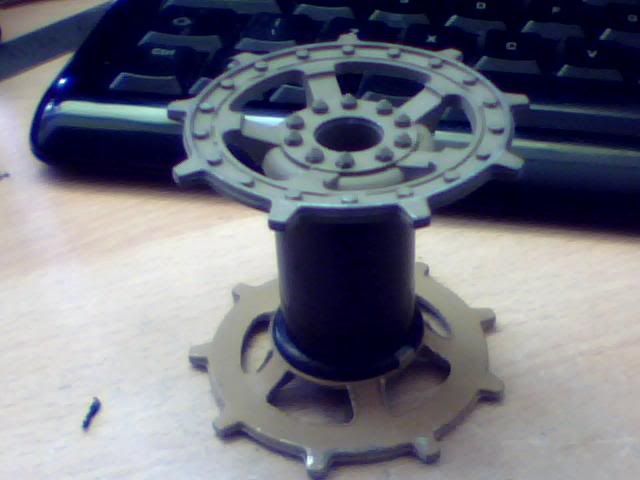
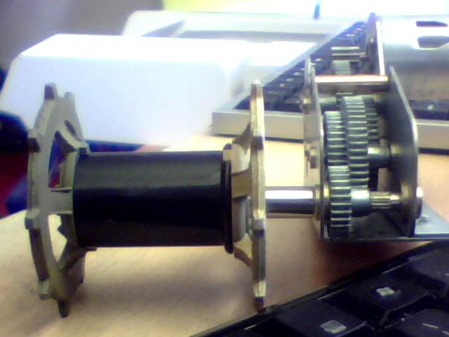
I don't know if I shared the drive arrangement previously but it just so turns out that someone bought a cheap car park playset for my son which he promptly destroyed, leaving me with some nice tubular parts for use in this build! I cut them in half and keyed one flanged end so it locates snugly with one of the sprocket parts I'm using (the drive wheels use 2 faces from my stock but no back) The other end is free and floaty but as this is the drive transfer anyway the whole thing will need major reinforcing at a later date. Here is the assembly as it currently stands...
Now I've been pondering how to further reinforce this and I'm left with quite a lot of options by the original manufacturers which is nice. I also have to figure out how to attach it to the motor however and that's rather more difficult as it'll be a pretty heavy assembly when finished supporting a LOT of heavy track and pulling a lot of stress... I think I'll need to dismantle the gearboxes and have some custom parts made here which can perform both jobs but we'll see...
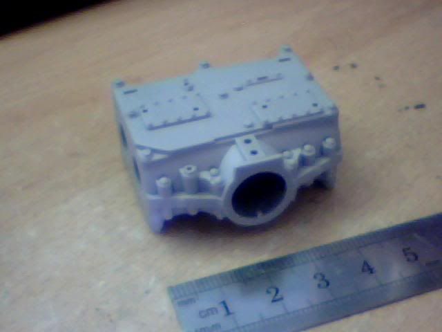
First things first, the loose end of the drive sprocket needs securing. The following image shows that the sprocket faces have these circular indentations on either side which go almost all the way through. They provide a perfect location for a reinforcing bar to pass through the black plastic sleeve and then right through the sprocket to prevent movement on one axis. Movement on the other axis is then prevented by the location of the locating lugs so with just this simple fix that end becomes permanently located.
I think it'll want a bit more than that to reinforce the central part of the assembly which is just plastic however... So my current thoughts are to replace the output shaft of the gearbox with a single piece of metal bar which can pass right through to the outer end of the drive sprocket and then have the short piece of bar pass through that as well. That would give me a watertight assembly I think as there would be no weak points (that I can think of!) Anyway, I'd already got one of these black plastic collars cut before yesterday but I've now done all four which took a surprisingly long time (getting the right length to mate the teeth to the track was a bit tricky!) Here is the piece of track I've already made with 2 full metal sprockets at each end and 3 of the home-made drive sprockets between them!
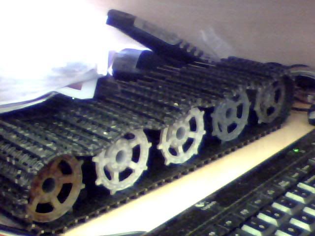
I can't help but think it actually looks pretty cool already

In the final build, only 2 of these wheels will be visible on each track though, the third hidden within the armour...
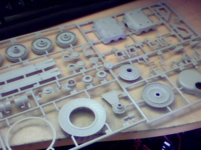
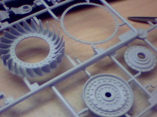
Anyway that's only part one of my dilemmas from yesterday. The next one arose when I realised that the two types of sprockets I have are actually slightly different sizes (I really could've checked earlier but I'd still have had to deal with it at some point!) This first image shows both types beside each other made into 'show' sprockets (ie. not used for drive...) and the one on the right is the new type I haven't started working with yet and it's slightly too big...
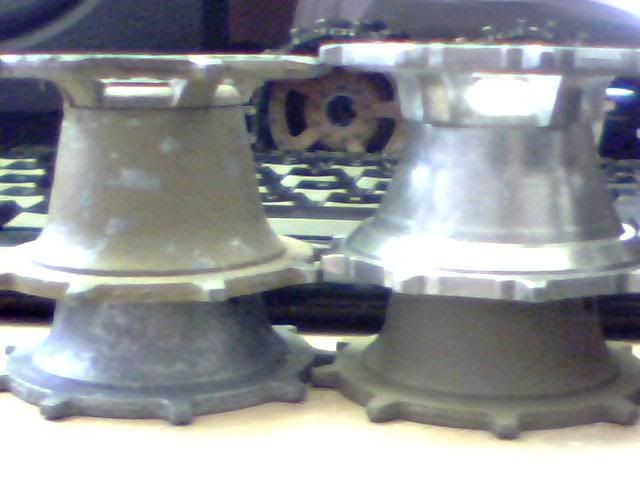
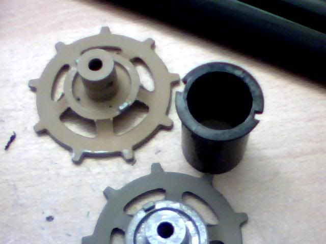
Now both types of sprocket have identical dimensions when assembled so the problem arises from my stacking them up like this as they seperate into 2 different pieces when compared to the ones I've been working with so far. Here are some piccys to illustrate the differences, the original is always on the left.
Split is lower on the new parts so bottom part is smaller;
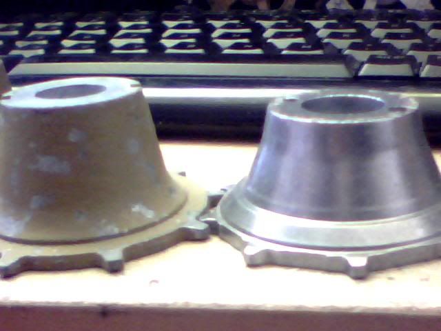
Top part is considerably altered but overall height is identical;
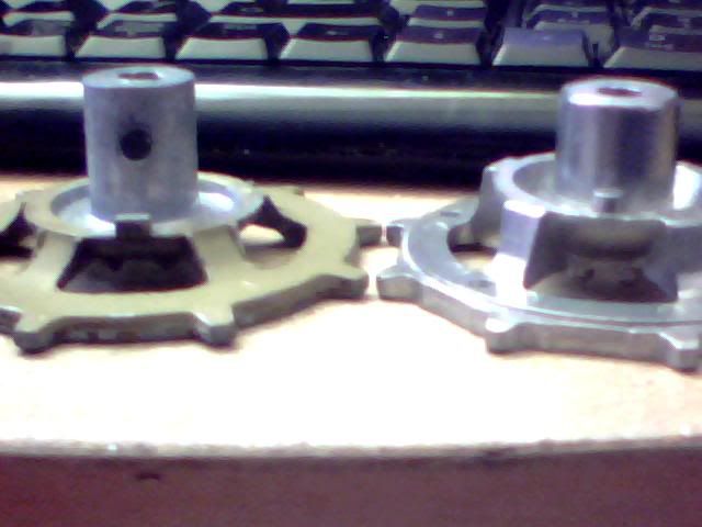
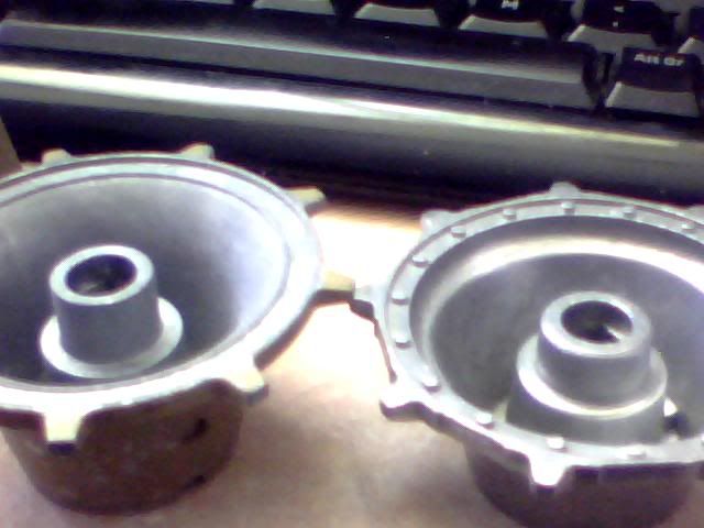
Underside very similar but new part has lower outer collar (stepped part inside) which causes it to sit higher when stacked;
Now the problem this causes should be fairly obvious, even if it appears quite slight. It does of course casu the lowest of the three sprockets to sit too far away from the other two, therefore pushing outwards on the track and struggling to locate. If there's one thing I've learnt doing this it's that 1mm matters as much in track building as it does in engine tuning
Thankfully there's a very simple solution to this so it's not really a problem. This solution is to close the 1mm gap by removing 1mm of metal, seriously, that simple! Because I don't want to ruin any of these parts (even though I have no intention of breaking this model up when finished I may upgrade tracks one day who knows!) I'll take the necessary material out of the inside of the bottom sprcket (the inside of the old set on which the new set is stacked) Don't worry, it's impossible to understand what I mean without pics and I don't have any as I haven't done it yet! Anyway, point is this will allow the new sprockets to sit an extra 1mm
inside the old bottom ones and therefore close the gap. It also leaves the old ones relatively unscathed and fully reuseable as intended in the future if necessary!
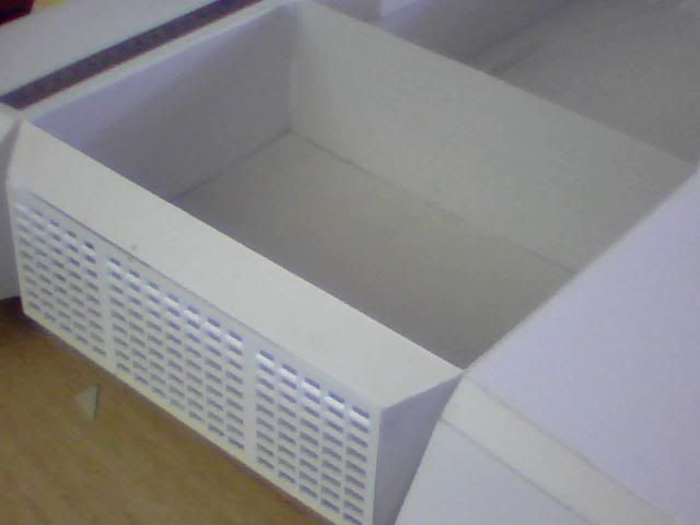
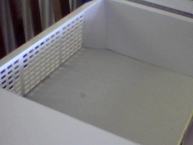
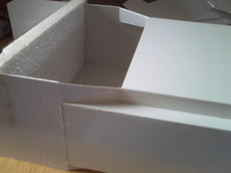
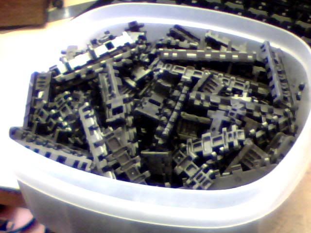
On top of my little brainstorming sessions I also spent a little time dismantling the next 148 links of track which needs to be cut'n'shut to form the second of four tracks. Here is my box of goodies which I'm thinking I'll put off for now until I can source some 1mm bar to cut my own track pins from. They simply MUST be one piece connectors and I'm not willing to cut up 300 of the King Tiger ones I have as a temporary solution! So if anyone knows where I can get some 1mm rod or bar (any metal is fine) then please let me know ASAP! Here is the track it's needed for, oh and I need about 22meters of the stuff for all four tracks please! Yeah seriously, 74 links at 74mm wide across four tracks. You do the maths...
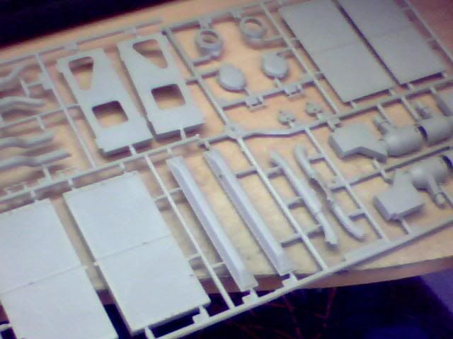
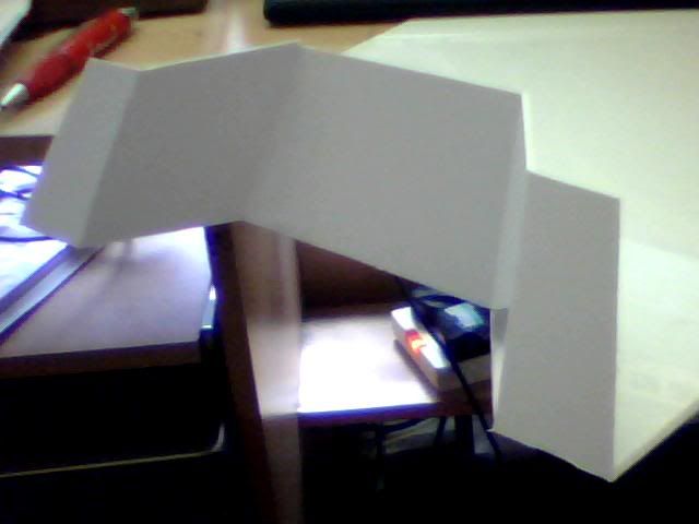
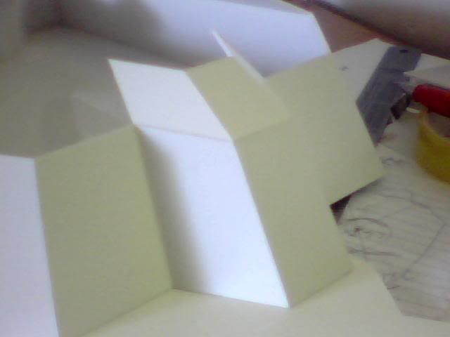
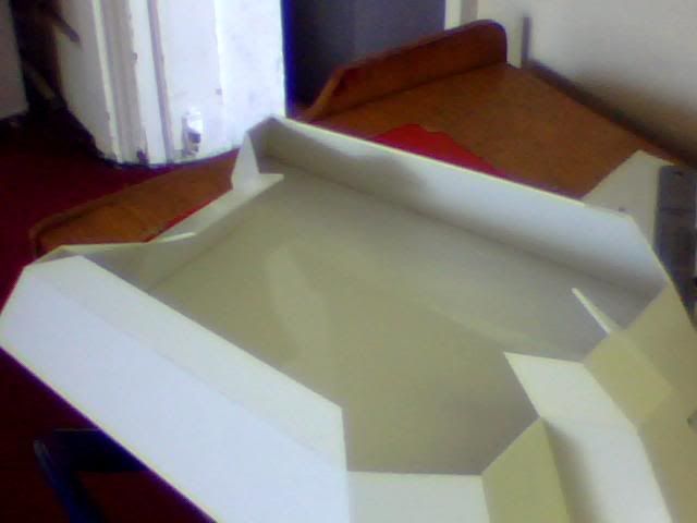
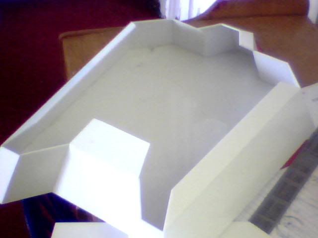
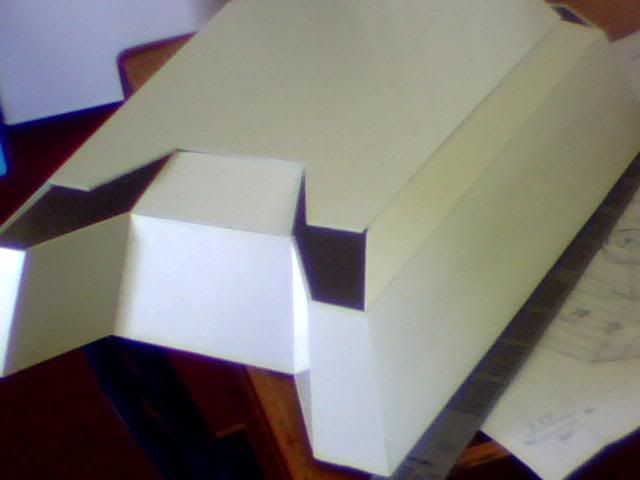
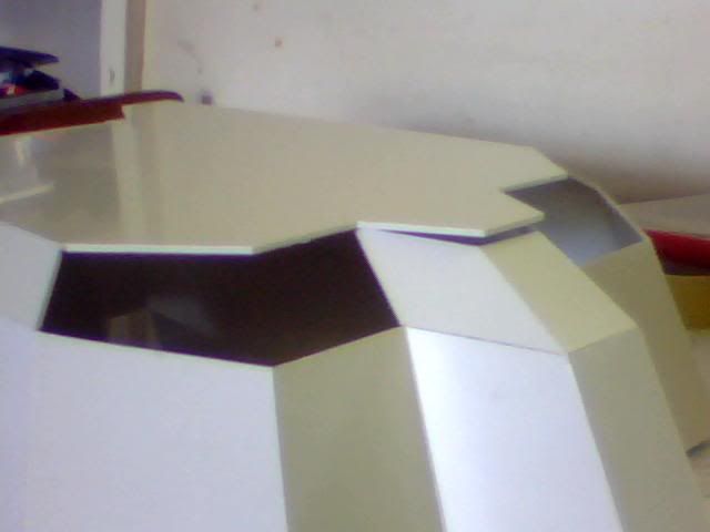
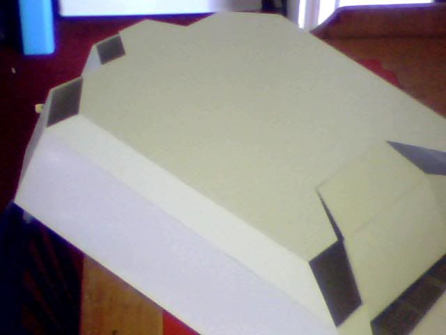
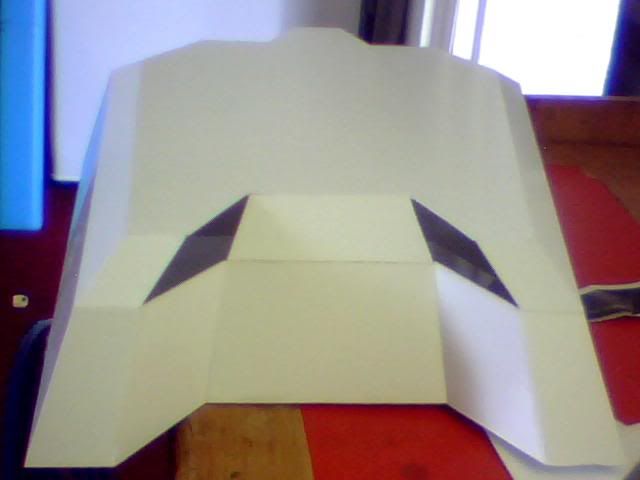
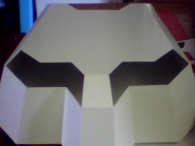
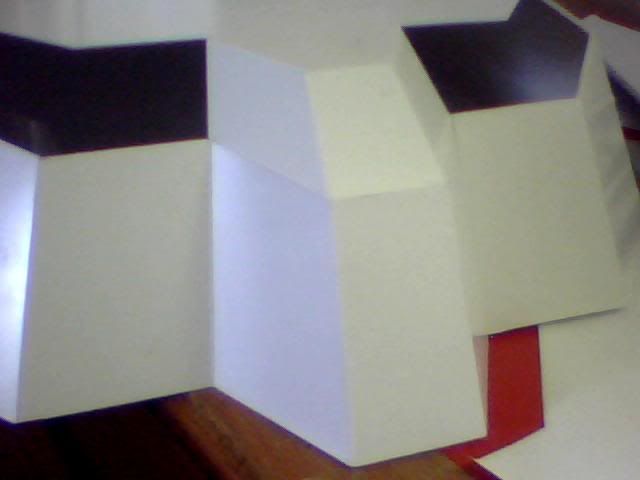
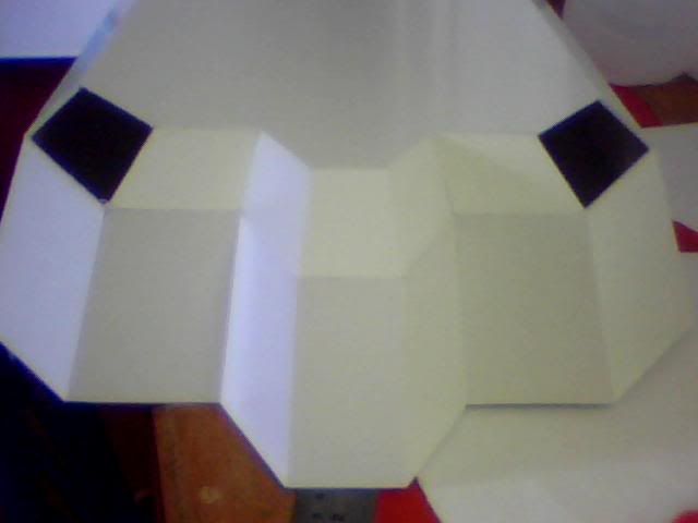
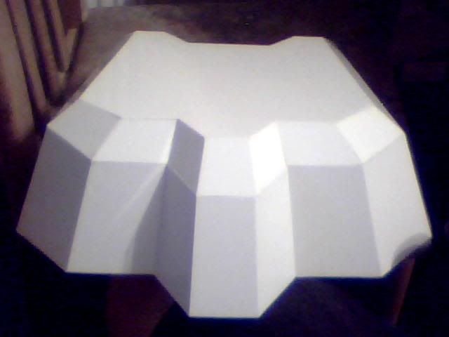
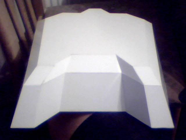
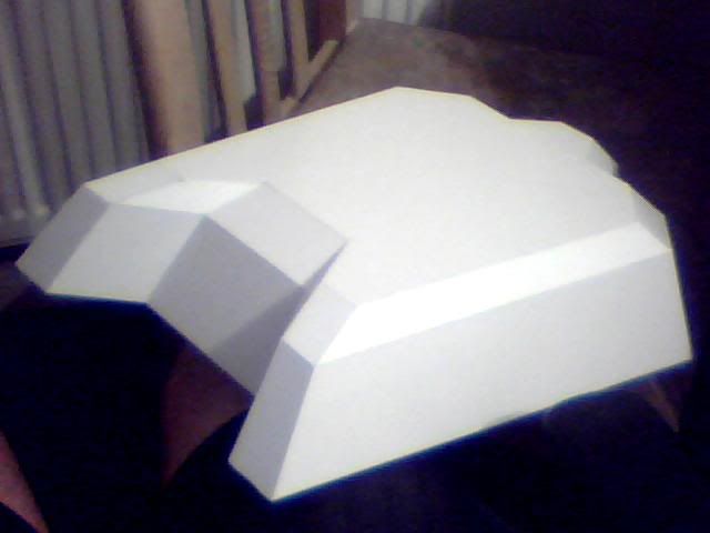
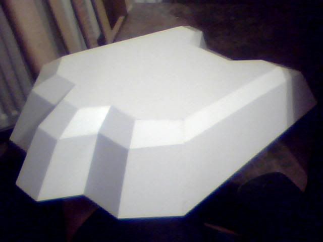
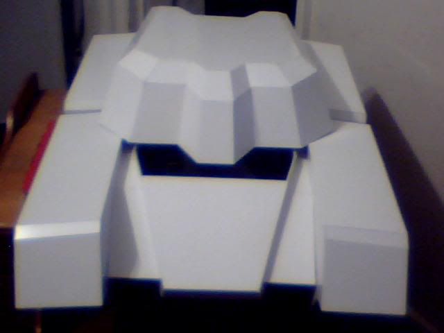
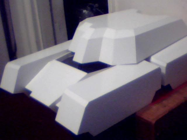
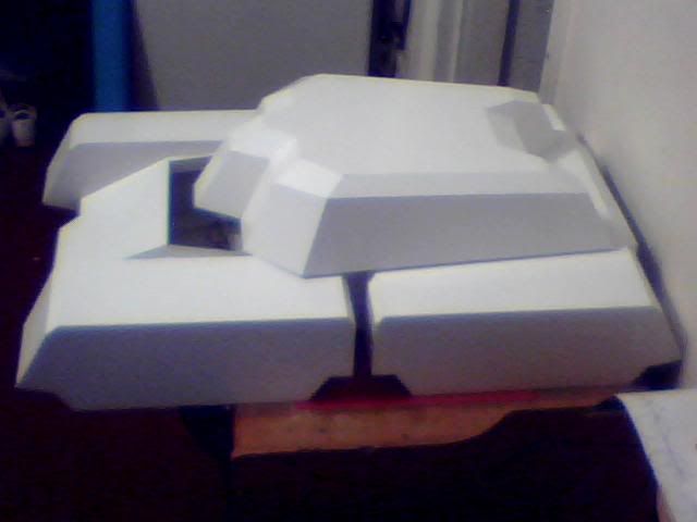
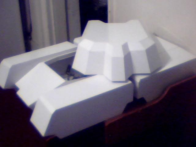
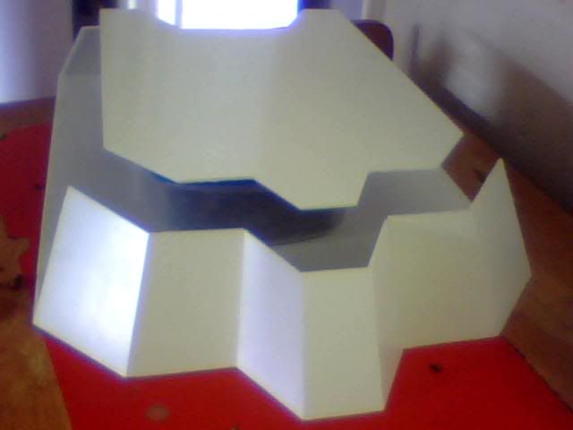
I've also done a little more work on the turret but my god is it giving me grief with all these horrible angles! I cut out the top part to give myself an idea of how the last few pieces need to fit together and while the front looks fien (can probably use my templates there) the back is horrendous and may well be altered slightly. Just don't tell anyone alright?! This is roughly where the top fits anyway but it'll be slanted back slightly so as to be higher at the front and tapered down towards the back. I'm only missing the two side pieces now which need recutting, grr biggest material wastage to date, and the one row of smaller pieces to connect the top to the bottom. Looking on the bright side I can probably use my bad side pieces to provide most of that material so all is not lost. I've actually been really good at controlling offcuts so far and have a very small amount of useable pieces left but a grand total of 3 intact sheets left over! So it's only taken me 6 so far and almost all the big pieces are done, just need to recut the hull top which I kinda bodged ages ago :p
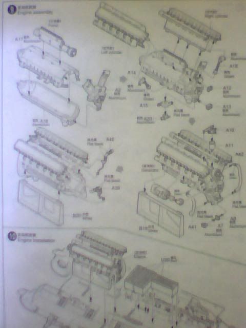
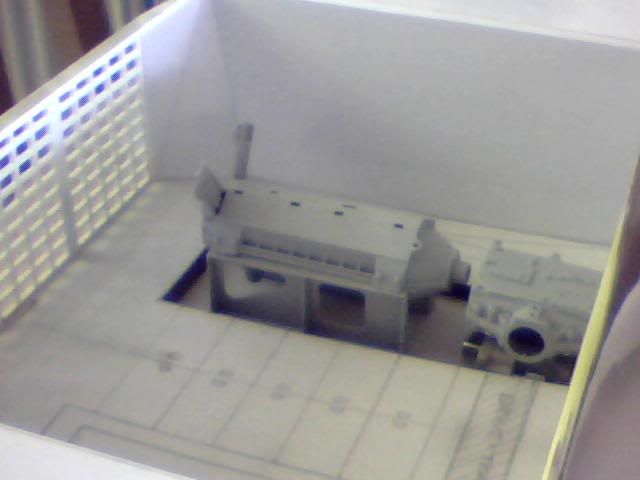
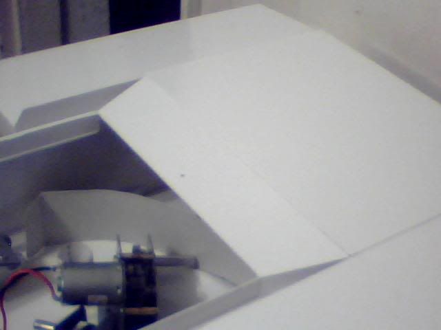
The final piece of discussion for today has already been mentioned and that's driving the tracks. This time though it's about the motor, not the sprockets... It's rapidly approaching the point at which I need to install the hardware into this beast and that means I need to figure out how and where for everything that needs fitting. There is amble room so that's not a problem and never will be! The 'unique' drive configuration is looking to be a little odd however as the drive wheels are located too high in the model to allow standard gearbox location. Here's my solution...
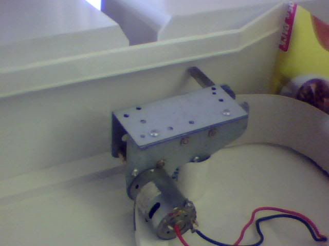
Yep, it's upside down! Bear in mind I have to be careful here as I have 4 motors and I have to keep the direction of rotation in check as well as which is left and right for control purposes! What I've done here though is simply taken a right hand gearbox and spun it through 180 degrees so it won't bother the rest of the hardware at all. I'll do the same with the left one (this is the rear track shown above) and just repeat it on the front with the second pair of motors... Each 'pair' will go to it's own board and then both will receive signal from the same controller in order to work both pairs simultaneously. Or at least that's the plan... I'm currently lacking a battery, crystals and a controller but everything else is already in place for movement. I still need turret hardware if anyone has spares.
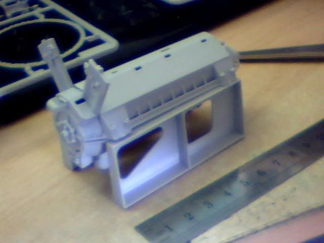
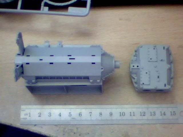
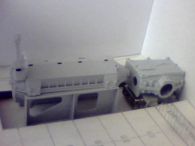
Anyway back to the physical process of transferring drive from the motor to the sprocket, I took a few images to illustrate the shortcomings I noted earlier. Here is a shot of where the motor will be in relation to the drive sprocket when everything is assembled.
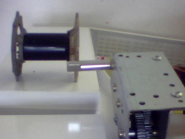
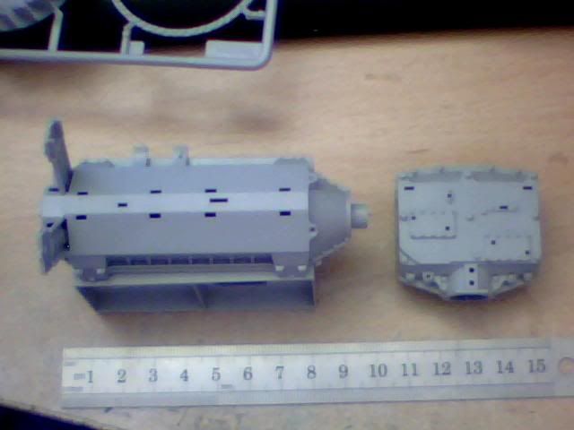
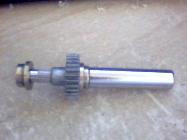
And here's where it WANTS to be in order to make physical contact with the itside of that first part of the sprocket...
So you can see there's about a 10mm gap there that I need to fill but just adding an extension onto the end of the current shaft will introduce a massive weakness into the system so I'm in favour of replacing it with a custom made part. I've just dismantled (very carefully!) one of my gearboxes to remove the final drvie shaft for some measurements and to try and figure out what I can do and how I can do it. I just knocked the gear off the shaft a bit and I see the whole assembly is made from one piece of turned rod. That means I'll need to have someone with a workshop make these things for me

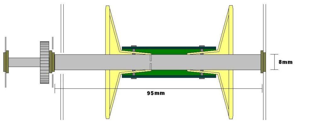
Anyway time for some rough estimates... Actually, forget rough estimates, I just sacrificed a small portion of my day throwing this together and actually it explains my thoughts rather well. Seems quite logical too so could quite easily be done by someone with a lathe or similar. Let me know if you want to help me!
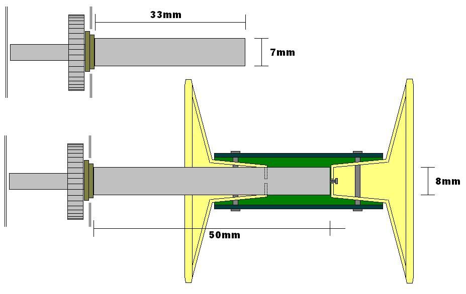
It needs to have a total length of about 75mm and a width of 8mm at the fattest point. I'll want a threaded hole in the outermost end which can be used to directly secure and centre the outer sprocket to the shaft and the first 25mm needs to have a width of 5mm so my bearing and gear can be fitted to it. That's it though, it's really that simple!
All it needs is a piece of metal rod to those specifications and a few modifications to drive my mammoth tank (well four pieces obviously) The bearing and gear willfit onto the narrow end which will then be able to be refitted to the gearbox. The outer end will fit first through the centre of one of the sprocket faces (which must be windened to allow for this) and then through the black plastic collar (in green here) and finally butt up against the inside face of the outer sprocket which will be bolted into the shaft. 2 rods will then be passed through the plastic collar, metal sprockets and drive shaft to ensure the entire assembly is completely solid.
Problem solved! Now who wants to make them for me? Please? Consider it an unofficial sponsorship deal lol
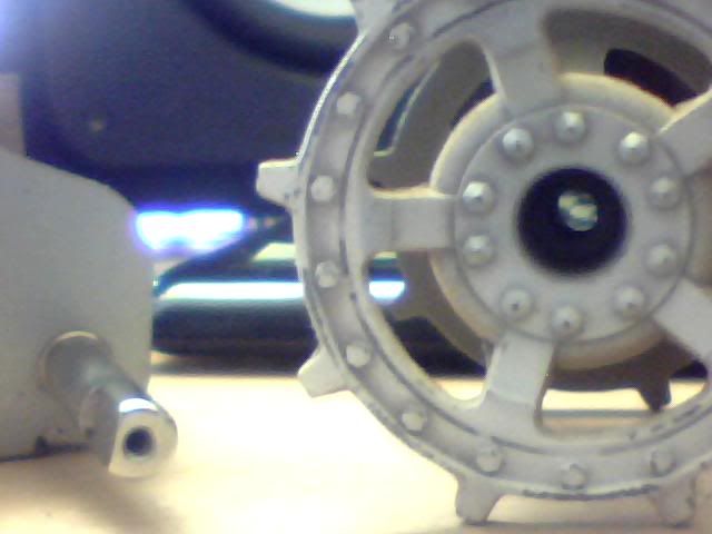
Anyway to finish up here's an image I should've posted earlier but it does go some way to show the part of these sprockets which will take both the bolt and the enlarging for the shaft.
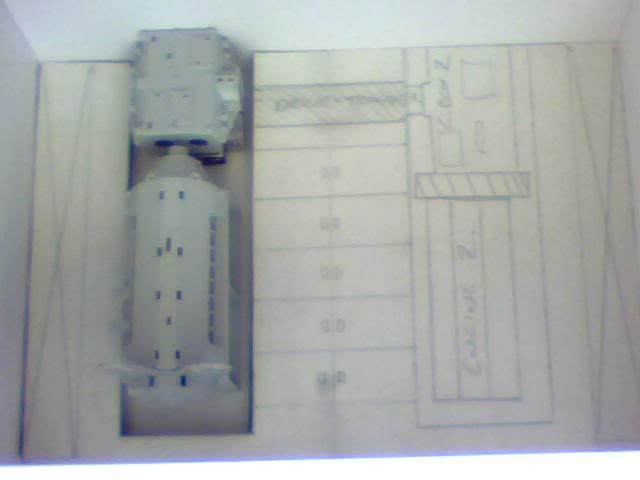
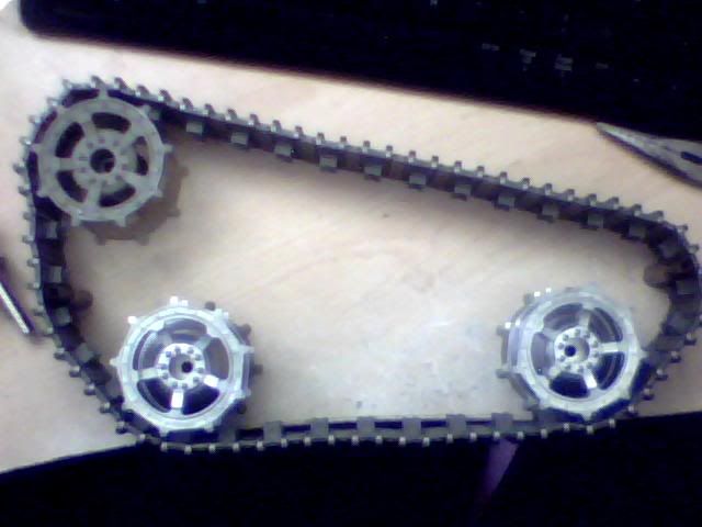
And finally, here is the track formation I've decided on but it's not proportionate... The top left wheel is the drive sprocket avec le tube plastiqe while the other two are full metal assemblies. The right side of the image is the outer edge of each track (ie the front of the front and the back of the back) while the drive sprockets will all be located centrally at the innermost corner of the assemblies. The two standy-uppy things on the left and right are actually spent blanks from my military days but are there to represent the two further points of contact I need to create to finish off this setup. I've pretty much decided I'll just run a metal bar from one side of the track housing to the other and then fit rollers on it for the track to pass over. Not going to bother with a tensioner if I can avoid it but we'll see. At the bottom there will be 4 bogey wheels between the two large metal ones which I'm planning to construct as two cantilevered double bogeys. And yes I'm aware that probably isn't correct terminology as it sounds like a golfing term but what are you going to do hey?!
So from here on out what do I need... Right.
I need some barrels making for me, 400mm long EXTERNALLY and then whatever else internally (it'll have a firing mechanism fitted). They're 120mm cannons so I guess a 6mm bore isn't too far off (bb size) but the last few inches could probably do with being 7 or 8mm to stop them looking so weedy on such a gigantic tank. The external diameter can be anything up to 30mm at the turret with a taper along the whole length to around 15-20mm at the business end.
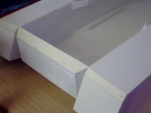
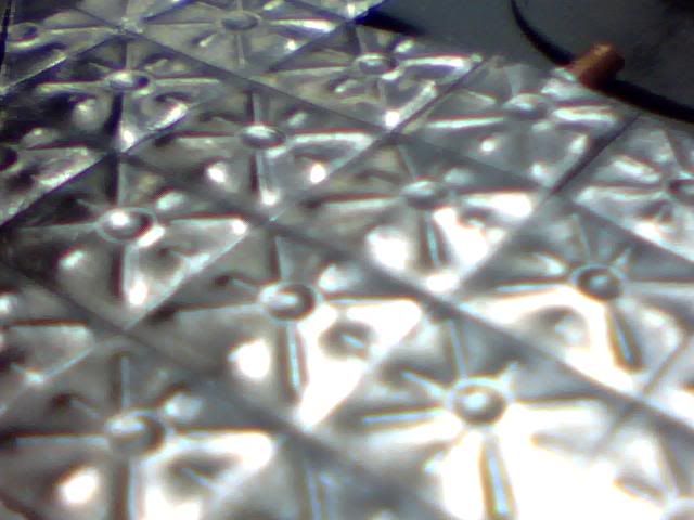
I'm also still looking for a suitable material for the floor in the engineering bay so anyone with advice on this sort of material in 1/16 please let me know your thoughts!

On further searching I just found this stuff which could be easily replicated with an old grill tray and some car grille material... Might do as a second choice...

I'm in the market for the turret gear I'll be needing too which is one motor for turning and lifting but two for firing...
Also still after a battery or two and one controller with two crystals that'll respond to it in unison!
As for progress... Well I need to re-cut the side pieces for the turret, re-cut the large top piece for the hull (which needs to be removable) cut a final small piece to finish the hull and individually craft the last 14 pieces to attach the turret top. I then need to cut the hole for the turret both in it's own base and in the hull top but thet'll wait till I have the motor for rotation for obvious reasons! Once the turret is finished it'll still be needing it's armament fitting which is not only the twin cannons but also 2 Tusk missile pods which I'll probably kitbash from some airfix planes or something (just a plasticard box with 6 rockets in it!) Then I need to detail the engine bay, reinforce the joins between the hull and the track pieces, brace the main compartment for the hardware, fit the hardware, test the hardware, fabricate new driveshafts, finish the last 3 tracks, alter the sprocket height, get hold of 21meters of 1mm metal rod and cut it into 300 pieces, scratchbuild 16 bogey wheels, deal with suspension, fit the wheels, mount the tracks, detail the armour plating, detail everything else then it might be about done...
Hmm...