The Clark board that I ordered from HAYA arrived today - this board has been pre-loaded with the correct Rolls Royce engine sound for the Centurion so I need to prepare the tank (and myself) in readiness to fit it.
I have no experience of electronics and I have never fitted-out a tank with all the electrical "gubbins" that is needed to make it drive, sound good, and have lights and muzzle flash........so this could be very interesting!
To try and install everything so that it works (and without blowing anything up) I will be seeking advice as I go and sharing this advice on here - just in case there is anyone else reading this that has as little knowledge about this mystical process as myself!
.....fingers crossed then..........
Amateur Build. HAYA Centurion KIT
HAYA Centurion KIT. Prepare for the Electrics!
Never too old to learn........
HAYA Centurion KIT. Out With The BB Mechanism.
I have chosen to have a "muzzle flash" in the gun barrel and so I need to find somewhere to thread the LED and the wires that power it up inside the barrel.
Fortunately I was able to ask Andrew at HAYA about this and he advised me to empty all the gears and springs (etc) out of the BB firing unit as I was not going to use any of it, and it would give me an ideal place for the wire and flash unit to enter the barrel.
I took the two halves of the BB firing unit apart and was quite surprised when a spring flew past my ear! I have never looked inside one of these BB units before, but I should have realised that there would be a reasonable sized spring inside it to catapult the BB out of the barrel when needed.
Everything came apart very easily and after I had wiped all (most) of the gear grease out of the unit, the two empty halves went back together easily enough.
Andrew advised that a 5mm hole could be drilled in the end of the unit to give a good entry point for the gun flash bulb and wires, and that it could also be used for the gun smoke tubing - if I should decide to add a smoking barrel feature at a later date.
I took the advice to drill a 2 mm hole first and then followed it up with the 5mm drill afterwards. This was a nice easy job that only took a minute or so to complete with the recoil servo still mounted (I had previously fitted it and glued the mount to the side of the BB unit)!
I think I may have done all I can to put-off and delay the scary bit - but next I need to delve into the "unknown" and start to give the electrical bits a "good coat of looking at"
- Attachments
-
- Empty BB unit rebuilt with Access Hole drilled - ready to be cleaned-up
- C1081BE1-CF85-486E-A439-06859522ED59.jpeg (616.81 KiB) Viewed 566 times
-
- Keep these parts but not the black Bell Crank (not needed).
- 2858339E-05D8-47DF-9F78-AB23891E2D80.jpeg (978.1 KiB) Viewed 569 times
-
- None of these parts are needed
- F6B82A12-5029-4FF1-B966-3FECE4A4BEB9.jpeg (1.14 MiB) Viewed 569 times
Last edited by zooma on Fri Oct 11, 2024 7:27 pm, edited 5 times in total.
Never too old to learn........
Amateur Build. HAYA. Electrics - Simple Stuff First.
Having removed the two front lamp covers from the glacis plate (I glued mine on by mistake!), the surface was cleaned-up and painted. The cyno de-bonder worked OK, but it was as thin as water and difficult to stop it from flowing over the plastic where it was not wanted!
The de-bonder left a white stain wherever it touched and in places where I was not quick enough to remove it, it actually left some mild burn marks on the plastic surface - so this stuff needs handling with care to avoid any preventable damage that may need correcting!
.....being a typical "bloke" - I avoided reading the instructions (!) and proceeded to drip the de-bonder onto the areas that needed to be un-stuck, and as soon as it touched these areas it decided it would rather explore any other part of the glacis plate - at an alarming speed!
Apparently I should have applied the fluid to a suitable cloth and rubbed it firmly into the area to be de-bonded - applying more fluid to the cloth as needed!
.......moving on - the two legs of the front light bulbs could now be threaded into the to pairs of holes that are pre-drilled ready to accept them.
My electrical knowledge has just been boosted (many times over) by Andrew who advised me that the long legs are + (positive) and the short legs are - (negative) .
Never too old to learn........
-
Herr Dr. Professor
- Major
- Posts: 6228
- Joined: Mon Apr 22, 2019 10:48 pm
- Location: Southern Wisconsin USA
Re: Amateur Build. HAYA Centurion KIT
"[T]he long legs are + (positive) and the short legs are - (negative)." This is such a simple matter. Yet I have not found such a straightforward answer despite searching. I wonder if this is true for all LEDs.

Re: Amateur Build. HAYA Centurion KIT
Should be. Nice part about LEDs is they are diodes which only allow current in one direction. Hooking it up wrong will not harm the LED. Overvolting them does produce a nice pop and a nasty smell.Herr Dr. Professor wrote: ↑Fri Oct 11, 2024 6:29 pm "[T]he long legs are + (positive) and the short legs are - (negative)." This is such a simple matter. Yet I have not found such a straightforward answer despite searching. I wonder if this is true for all LEDs.
Derek
Too many project builds to list...
Too many project builds to list...
HAYA Centurion KIT. Another Delaying Tactic?
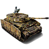
Another thing that I think I should do before fitting any electrical parts is to get some paint on the turret.
At the moment the bottom and central sections of the turret are still in the original loud plastic moulding colour of Kermit Green and the replacement Mk5 turret top came painted in Deep Bronze Green - so no part of the turret is painted in the Olive Drab that this tank will be finished in.
I will get these parts painted before fitting any more electrics..............
- Attachments
-
- Two Shades of Green - but neither are Olive Drab.
- 1A49492F-DFB1-4B20-BE5C-E2DB468B06E5.jpeg (785.13 KiB) Viewed 556 times
Never too old to learn........
-
ongbenghui
- Private
- Posts: 99
- Joined: Sun Jun 18, 2023 6:43 pm
Re: Amateur Build. HAYA Centurion KIT
Yeah... pin packaging. and a small flat spot on the - Negative terminal. The same applied for 2 pins IR emitter and receiver too.Herr Dr. Professor wrote: ↑Fri Oct 11, 2024 6:29 pm "[T]he long legs are + (positive) and the short legs are - (negative)." This is such a simple matter. Yet I have not found such a straightforward answer despite searching. I wonder if this is true for all LEDs.
T-1 3/4 packaging for 5mm
T-1 packaging for 3 mm
https://en.wikipedia.org/wiki/Light-emitting_diode
HAYA Centurion KIT. Vision Block(?)
I have sprayed the turret all over with Tamiya TS-5 Olive Drab, so it is now looking a little more "uniform" (no Kermit Green) so the small detail parts that fit on top of the turret stand-out like a sore thumb - because they are still Kermit Green coloured !
........but one of them is missing......
I think it is called a "vision block" ? It fits on top of the "brick" shaped block in front of the rotating cupola and it will have a locating pin on its underside to fit into the hole on the top surface of this "brick".
........but one of them is missing......
I think it is called a "vision block" ? It fits on top of the "brick" shaped block in front of the rotating cupola and it will have a locating pin on its underside to fit into the hole on the top surface of this "brick".
- Attachments
-
- Spot the missing part.....
- 33544CE0-A2BC-4938-B996-A378E63B9BFA.jpeg (674.3 KiB) Viewed 508 times
Never too old to learn........
-
jarndice
- Colonel
- Posts: 8497
- Joined: Mon Sep 03, 2012 11:27 am
- Location: the mountains of hertfordshire
Re: Amateur Build. HAYA Centurion KIT
You are probably right but I just wondered if the hole was for the Turret MG mount, Just a thought 
I think I am about to upset someone 
-
Herr Dr. Professor
- Major
- Posts: 6228
- Joined: Mon Apr 22, 2019 10:48 pm
- Location: Southern Wisconsin USA
Re: Amateur Build. HAYA Centurion KIT
zooma: I keep all those nice little gears, springs, etc., that you show in the photo. I keep thinking that someday I will find them useful. Hence, my modeling area is also a junkyard.
"Hooking it up wrong will not harm the LED." Thank you, tankme and ongbenghui: I certainly know about the need to make sure LEDs have the correct (generally lower) voltage, but I was not sure about current direction.
"Hooking it up wrong will not harm the LED." Thank you, tankme and ongbenghui: I certainly know about the need to make sure LEDs have the correct (generally lower) voltage, but I was not sure about current direction.
