
Derek
Make one 1/16 sd.kdz.234/2 PUMA
Re: Make one 1/16 sd.kdz.234/2 PUMA
Well I just purchased the IS-3 files and I think I've got all the ones on Thingiverse. Now I just need the time to print and build them. 
Derek
Derek
Derek
Too many project builds to list...
Too many project builds to list...

Re: Make one 1/16 sd.kdz.234/2 PUMA
- IMG_20230315_185710.jpg (1.77 MiB) Viewed 1690 times
- IMG_20230315_185651.jpg (2.24 MiB) Viewed 1690 times
- IMG_20230315_185645.jpg (1.7 MiB) Viewed 1690 times
Fortunately, all the electronic equipment has been sent. I tested it and found no problem
Re: Make one 1/16 sd.kdz.234/2 PUMA
- IMG_20230319_000142.jpg (1.91 MiB) Viewed 1658 times
- IMG_20230319_000132.jpg (2.16 MiB) Viewed 1658 times
- IMG_20230319_000121.jpg (1.93 MiB) Viewed 1658 times
- IMG_20230319_000113.jpg (1.96 MiB) Viewed 1658 times
- IMG_20230319_000104.jpg (1.97 MiB) Viewed 1658 times
- IMG_20230317_155436.jpg (1.61 MiB) Viewed 1658 times
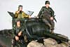
You can see in the picture two sets of linkage steering mechanisms, as well as an unfinished smoke system.
There are still some parts that are not in place yet. I believe I will be able to complete them soon
Re: Make one 1/16 sd.kdz.234/2 PUMA
According to my calculation, the weight of my PUMA fully loaded (including batteries and various electronic systems) is 1.2-1.4KG. In fact, I believe that 1/16 RC tanks should not be too heavy, and lighter weight can ensure lower costs. Moreover, due to the lighter load of the vehicle, reliability will also be greatly improved.
Re: Make one 1/16 sd.kdz.234/2 PUMA
- IMG_20230319_212018.jpg (2.07 MiB) Viewed 1612 times
- IMG_20230319_213823.jpg (1.94 MiB) Viewed 1612 times
- IMG_20230319_213902.jpg (2.08 MiB) Viewed 1612 times
Re: Make one 1/16 sd.kdz.234/2 PUMA
This is a really nice project.
Derek
Too many project builds to list...
Too many project builds to list...

Re: Make one 1/16 sd.kdz.234/2 PUMA
I am really impressed with the project. I'd call it a scratch build just with CAD and a printer instead of card and glue.
"Don't believe everything you see on the internet" - George S. Patton
Eric
Eric
-
Herr Dr. Professor
- Major
- Posts: 6126
- Joined: Mon Apr 22, 2019 10:48 pm
- Location: Southern Wisconsin USA
Re: Make one 1/16 sd.kdz.234/2 PUMA
Another fine quality of this project is the neatness of the design, the fitments, even the printing.
-
Will01Capri

- 2nd Lieutenant
- Posts: 2709
- Joined: Tue Jul 18, 2017 5:34 pm
- Location: South Scotland
Re: Make one 1/16 sd.kdz.234/2 PUMA
Looks really very good, excellent work
Would love to see some running videos aswell
Would love to see some running videos aswell
HL camo E' Tiger
HL L' Tiger
M26 Pershing WW2 project
Tam K'Tiger project
HL Walker Bulldog project?
HL Panzer IV Munitionsschlepper für Karl-Gerät
HL Sherman project?
1/24 Leopard 2 Custom mod
2 many trucks to list!
HL L' Tiger
M26 Pershing WW2 project
Tam K'Tiger project
HL Walker Bulldog project?
HL Panzer IV Munitionsschlepper für Karl-Gerät
HL Sherman project?
1/24 Leopard 2 Custom mod
2 many trucks to list!
Re: Make one 1/16 sd.kdz.234/2 PUMA
- IMG_20230324_004708.jpg (109.31 KiB) Viewed 1521 times
- IMG_20230324_004719.jpg (69.32 KiB) Viewed 1521 times
- IMG_20230324_004722.jpg (77.1 KiB) Viewed 1521 times
- IMG_20230324_004731.jpg (85.53 KiB) Viewed 1521 times
- IMG_20230324_004742.jpg (108.57 KiB) Viewed 1521 times
- IMG_20230324_004750.jpg (76.54 KiB) Viewed 1521 times
- IMG_20230324_004817.jpg (135.44 KiB) Viewed 1521 times
- IMG_20230324_004825.jpg (81.8 KiB) Viewed 1521 times
- IMG_20230324_004848.jpg (124.13 KiB) Viewed 1521 times
- IMG_20230324_004940.jpg (141.23 KiB) Viewed 1521 times
I powered on and tested that the suspension and steering parts worked well. However, due to the low voltage, the power of the motor is weak, and the driving speed on flat ground is very slow. Therefore, I purchased a new 3S lithium battery, a new electronic governor, and a step-down module. Since the main board can only use 7.2 volts, I first need to connect the electrical regulator and step-down module responsible for the main motor in parallel. This way, the system responsible for advancing has a voltage of 12V, while the rest of the system is still 7.2V
