M1A1HA, 9/18/23 update. Delay of Game, two week penalty!

User avatar
BarryC
2nd Lieutenant
Posts: 2491
Joined: Sun Jan 03, 2016 11:43 am
Location: Savannah, GA. USA

Re: M1A1HA, 7/31 Update, More "Devilish" details.

Post by BarryC »

Thanks guys!

Sometimes it does feel a little crazy. :crazy:

Barry
"Details make perfection, and perfection is not a detail."
Leonardo Da Vinci
User avatar
BarryC
2nd Lieutenant
Posts: 2491
Joined: Sun Jan 03, 2016 11:43 am
Location: Savannah, GA. USA

Re: M1A1HA, 7/31 Update, More "Devilish" details.

Post by BarryC »

Hi Folks,

After 2 weeks of trying to get back into the swing I think I’m back at it. I’ve moved my focus back to the engine deck. There are still lots of small details to add. So, I started by “planting” bolts on the NBC panels then on to the bolts securing the main engine access cover. I also drilled locations for other but have not “planted” them yet. I am using Master Club gray resin Bolts with and without Washers.

Image

There are several “L” shaped angles that are used to secure a rubber “wiper” to the rear deck beneath the turret. I used brass angle, bar stock and more of the latex material from “Kinky Engineering”. Once I got them made I placed the turret base on to see how it all looked. Well it did not look that great, too large a gap between the turret and the hull. I had noted it earlier but thought I could live with it but NO!

Image

Image

Image

So, I’ve spent the last two days lowering the turret. I figured it needed to come down about .100” but that would place the turret gear ring into contact with the sponson extensions on the lower hull. After much thought I decided I could lower it .080” and get a much-improved look and still have .020/.030” clearance on the moving parts inside the tank.

Image

Image

Lowering the turret required removing the turret mount ring/hole from the upper hull. Then reattaching it .080” lower. This took quite a while as I need to remove it without losing too much material from the saw cut. I replaced the lost diameter by gluing .015” styrene strip to the cut edge. I attached a .060” mounting flange cut to the inside face of the hull giving me a structurally sound mounting surface to reattach the turret ring. I reattached the turret ring using 0-80 nylon screws. I may epoxy it as well once I am happy with the fit and function. All this necessitated removing corresponding material from the lower turret piece circular flange, ring gear mounting posts and the ring gear circular flange. This was needed to create the proper spacing between the ring gear and the lower turret. A lot of work but it turned out good and the turret to hull space looks much better.

Image

Image

Image

I have also installed the Handles and Locking tabs for the storage bin on the right side of the hull. I used Schumo handles from ETO Armor, they look great. The challenge was the hinges for the cover as they do not actually hinge. Due to the close fit of the turret the cover there is no room for the cover to hinge open and allow access to the storage area no matter the positioning of the turret. The cover has tabs of sorts that fits into the “U” channel which secures the cover on the inside. It’s a removable cover as opposed to a hinged cover.

Image

TTFN
Barry
"Details make perfection, and perfection is not a detail."
Leonardo Da Vinci
User avatar
BarryC
2nd Lieutenant
Posts: 2491
Joined: Sun Jan 03, 2016 11:43 am
Location: Savannah, GA. USA

Re: M1A1HA, 9/14 Update, Handles, Hinge Pins and Bolts

Post by BarryC »

Time for another update.

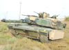
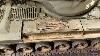
Details, details, and more details. I have been working to complete all the detail work on the rear deck of the upper hull. I remember Herman saying one of the modelers here said that the Abrams was “festoon” with handles and that’s a fact. There are 16 handles 14 of which must be hand formed from brass rod/wire.

Handles:
5 of the handles are .028” brass rod. 5 of them have two #80-.0145” holes drilled through them for retainer drive pins. Those 5 also have two .12mm washers and a small spring formed from .012” brass wire. These act both as handles and locks for access doors/panels.

Image

9 are formed from the same .028” rod and are mounted with a .125” length of aluminum tube epoxied to the deck. 8 are for lifting access doors/panels and 1 is the forward hoisting point for removing the large access cover for engine removal/replacement.

Image

Image

The remaining two are the handle/locks for the storage box and are made by Schumo for the M26 Pershing.

Image

Hinge Pins:
There are 19 hinge pins made from .020” brass rivets with a .12mm head filed flat. 17 have a #80-.0145” hole drilled through each for cotter keys. Cotter Keys are made from .006” brass wire, oh yes they are great fun to make!

Image

The remaining two are Ball Lock (PIP) pins which can be quickly removed by hand.

Image

Hold Down Arms:
Each of the 8 hold down arms has a Hex Head Pivot Bolt. I made these by taking a .07mm brass bolt and rounding the head. I still must drill a small hole in the head to simulate the hex key opening.

Image

Hold Down Bolts:
There are 22 bolts that secure the FOD/Debris Air Intake Screens. Thankfully they are straight forward brass bolts with washers. The are 25 bolts that secure the NBC access panels as well as another 56 that for various other access panels ranging from .05mm to 1.6mm. These are all Master Club resin casting with and without washers.

Image

Image

Image

Fueling Cover Lock Handle Retainers:
Each of the lock handles has a securing mount with a spring tension retainer that secures the handle in the locked position. I fabricated them from brass bar and thin brass shim stock. Each is mounted with two .08mm brass bolts. The shim stock is formed in such a way as to have enough spring tension to keep the handle in the locked position. They are two more to be made for the forward fueling covers.

Image

Image

Over Pressurization Vent:
I formed this using .125” brass tubing. I clamped and soldered one end closed then shaped it as seen. I took a thing piece of .125” shrink tubing cut to approx. .060” to form the lip of the rubber end cap where it is secured with a KA Models, 1/12-1/20 scale, automotive hose clamp.

Image

Image

Image

Next up:
I started moving forward along the hull and decided it was time to tackle the retainer pins used on the mounting pins for the skirt panels. Here’s a first look at a couple I’ve made using a brass bolt file to a rectangular shape with #76-.020” holes drilled approx. .020” deep into each “short” side to accept a .0625” ID retainer ring formed from .016” piano wire.

Image

TAFN
Barry
Last edited by BarryC on Fri Sep 14, 2018 8:55 pm, edited 1 time in total.
"Details make perfection, and perfection is not a detail."
Leonardo Da Vinci
User avatar
Soeren
Warrant Officer 2nd Class
Posts: 1356
Joined: Sat Oct 22, 2016 3:27 pm

Re: M1A1HA, 9/14 Update, Handles, Hinge Pins and Bolts

Post by Soeren »

Ok, the hoseclamp was a premade scale model piece?
User avatar
BarryC
2nd Lieutenant
Posts: 2491
Joined: Sun Jan 03, 2016 11:43 am
Location: Savannah, GA. USA

Re: M1A1HA, 9/14 Update, Handles, Hinge Pins and Bolts

Post by BarryC »

Soeren wrote:Ok, the hoseclamp was a premade scale model piece?
Yes as described, it is by KA Models. I did rework the fastener used for tightening with a piece of brass tubing and a brass bolt.

Barry
"Details make perfection, and perfection is not a detail."
Leonardo Da Vinci
User avatar
Soeren
Warrant Officer 2nd Class
Posts: 1356
Joined: Sat Oct 22, 2016 3:27 pm

Re: M1A1HA, 9/14 Update, Handles, Hinge Pins and Bolts

Post by Soeren »

Those are some fantastic details added. Great you have these pictures, as most of this will be less obvious when you eventually get around to paint this.
User avatar
Model Builder 4
2nd Lieutenant
Posts: 2425
Joined: Sun Jul 26, 2015 3:46 pm
Location: South Wales valleys
Contact:

Re: M1A1HA, 9/14 Update, Handles, Hinge Pins and Bolts

Post by Model Builder 4 »

The level of detail is just outstanding Barry, this piece will surely end up in a military museum :thumbup:

Cheers, Lee.
Me ? Addicted ? Never !! :crazy:
User avatar
square4
Lance Corporal
Posts: 205
Joined: Thu Jun 21, 2018 11:45 am
Location: Southport

Re: M1A1HA, 9/14 Update, Handles, Hinge Pins and Bolts

Post by square4 »

Can't add anything to whats already been said, its just superb work. :clap:
I never finish anyth
User avatar
BarryC
2nd Lieutenant
Posts: 2491
Joined: Sun Jan 03, 2016 11:43 am
Location: Savannah, GA. USA

Re: M1A1HA, 9/14 Update, Handles, Hinge Pins and Bolts

Post by BarryC »

Thanks guys! :D

With most task figured out I hope to finish up the upper hull over the next week or so. The one task I still have to work out is the Headlight Brush Guards but I've got a good idea, I :think: ?

Cheers,
Barry
"Details make perfection, and perfection is not a detail."
Leonardo Da Vinci
User avatar
BarryC
2nd Lieutenant
Posts: 2491
Joined: Sun Jan 03, 2016 11:43 am
Location: Savannah, GA. USA

Re: M1A1HA, 9/14 Update, Handles, Hinge Pins and Bolts

Post by BarryC »

Son of a gun-ner wrote:Barry seems to find more and more to detail the closer he gets to painting, I'm sure he's using delay tactics ;)
Oops you've caught me Mick, I guess the jig is up. :O

Barry
"Details make perfection, and perfection is not a detail."
Leonardo Da Vinci
Post Reply

Return to “Abrams”