HENNTEC IDLER QUESTION

If you have a tank query and you can't find the answer anywhere else, post here. (TIP - Check for answers in FAQ, use the 'search' facility or even check this board before posting here).
Forum rules
If your question is electronics related please post it in one of the relevant boards here: viewforum.php?f=31
Post Reply
SCHWEREPANZER
Sergeant
Posts: 593
Joined: Thu Jan 08, 2015 1:40 am

HENNTEC IDLER QUESTION

Post by SCHWEREPANZER »

Hi All,

Embarrassed to ask what seems so obvious, but here goes. I want to install a Henntec No. 11 Tiger I idler set up on a Chris Ludwig Panther II polystyrene kit. I'm pre-fitting all the running gear parts, but have run into a theoretical roadblock, not really being of an engineering bent of mind. I realize that the Henntec is probably overkill for what will be a static model (anathema to many here I know, but please don't shoot the messenger). I've searched here in the forum and elsewhere and found easy to understand (even for me) installation instructions. But, having the pieces in hand, I'm still confounded by the workings of the hub-attached part.

This:
20180430_172923 (450x800).jpg
20180430_172923 (450x800).jpg (95.14 KiB) Viewed 1319 times
My question is this: Once loosening the hub set screw (the one on the right in the picture), which I assume (rightly or wrongly) allows the hub to loosen the small shaft running through to the idler wheel lug, shouldn't I be able to turn the shaft within the hub mechanism? Otherwise, how could the idler hub be moveable since it's attached to the hull side with the small attaching screw. As it is, I cannot turn the shaft with the hub even with the set screw removed.

I know the answer resides within the august body which resides herein. :D
sassgrunt
Staff Sergeant
Posts: 751
Joined: Wed Oct 29, 2008 9:08 am
Location: Hawaii, USA

Re: HENNTEC IDLER QUESTION

Post by sassgrunt »

Hey Schwerepanzer. From my own experience with these, (and I am a fan of them, as they are so much more robust than the stock setups), they are meant to allow you to rotate the idler to obtain the track tension you want, and then to lock it down, (there is no automatic moveable tension once you lock it down). From your photo, I believe the inner hub is inside out. The smaller diameter of the hub is what you drill out the hull to accept, and the hub is installed from the inside of the hull. The hull is drilled so that the small screw-and-nut holds the hub in position, (since the lockdown grub screw is on the inside of the hull, you'd want to drill the hull for that small screw so that the grub screw always faces upward - where you can get at it with the hex wrench). If you look at the photo you posted, the inner hub (the way it sits right now), should go on the right side of the hull. That way the small screw can go forward of it, because you may have to cut/grind off some of the rear of the large flange of the hub to fit the rear wall of the hull, (on the Panther II, there is probably little room between the idler and the rear wall). I would use the idler arm on the right side as well; although the set screw for the idler axle would then be on the underside of the arm....but that is also where the set screws for the roadwheel arms are located.
If I have only served to COMPLETELY confuse you; I hope that maybe someone can translate all this more simply. -Mike
sassgrunt
Staff Sergeant
Posts: 751
Joined: Wed Oct 29, 2008 9:08 am
Location: Hawaii, USA

Re: HENNTEC IDLER QUESTION

Post by sassgrunt »

Well, maybe I've been doing it wrong. If you take the hub and install it with the orientation that is showing in your photo, one of two things will result - either you install it from the outside of the hull; resulting in a large unsightly flange, (and it also has interference from the raised 'hub' surround that Tamiya molded onto the outside of the hull - unless you cut that away), or you install it from the inside of the hull, and then that raised 'hub' covers up the grub screw lockdown so you can't adjust it. Even on other hulls than Tamiya, the thickness of the hull alone can cause difficulty getting at that grub screw.
I've had my best luck installing it from the inside, with the flange and lockdown screw on the inside of the hull.
sassgrunt
Staff Sergeant
Posts: 751
Joined: Wed Oct 29, 2008 9:08 am
Location: Hawaii, USA

Re: HENNTEC IDLER QUESTION

Post by sassgrunt »

Nope, I didn't take it as a correction, Mick - only as several people trying to out-guess the lack of proper instructions. I haven't tried it, but it may be possible to install it from the inside in the orientation your photo shows, and drill an access hole that matches the lockdown grub screw in that raised part that Tamiya molded in. Not sure if the thickness of the hull, (and remember, there's a metal inner tub, too), would allow this.
SCHWEREPANZER
Sergeant
Posts: 593
Joined: Thu Jan 08, 2015 1:40 am

Re: HENNTEC IDLER QUESTION

Post by SCHWEREPANZER »

Thanks Gents,

Mr. Son's picture is of the Henntec unit I have. The picture shows how the system as it would be placed on the tank. That is, with the black bosses which accept the idler wheel through the hole in the bottom of the cam shaped boss itself obviously on the outside of the hull and the small axle fitted in the brass bar inside. The idea is to allow the idler to be adjusted by loosening the set screw, moving the cam idler boss forward or backward to adjust the track, and then tightening the set screw which locks down the small axle, all from outside the tank.

The question is: when loosening the set screw the one on the right in my picture), shouldn't you simply be able to turn the small metal axle rod (that sits inside the hollow brass rod) with your fingers? Or put another way, with the set screw loose, shouldn't the external idler be moveable simply by moving it with a finger? The small screws with tiny washer and nut on the top of Mr. Son's picture are for securing the assembly to the tank. The hole for this has to be drilled through the lower hull, the small screw inserted and then secured by the small washer and hex nut. Thus, the whole assembly is rigid when attached and secured by the small screw and nut. The external parts (the black bosses) therefore have to be able to move forward or backward around the small axle to adjust the track tension. Right? When you think you have the correct tension on the track, you tighten down the set screw. Problem is, I cannot move the small axle even when the set screw is removed from the boss. Where am I going wrong?
User avatar
Guido Henn
Lance Corporal
Posts: 212
Joined: Mon Jan 27, 2014 6:01 pm
Contact:

Re: HENNTEC IDLER QUESTION

Post by Guido Henn »

Hello Ralph,

i did not understand what the problem is,but perhaps a manual in english can help.
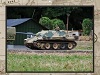
011


Step 1. Remove the idler wheels and the two nearest road wheels on each side next to the idlers. Remove the hull rear plate. 


Step 2. Using a cut off wheel or small saw, remove the stock Heng Long idler mount as per the photo.


Step 3: To determine the location of the new 13 mm hole needed to mount the HennTec idler system, use the HennTec idler arm provided in the kit. Put the mounting shaft of the idler arm in the existing Heng Long idler hole, rotate the idler arm up to exactly 12:00 o'clock, in other words straight up, mark the new hole location using the idler axle hole in the idler arm, and make a 13 mm hole in this position. 


Step 4: Prepare the mount area inside the hull by removing part of the molded in ridge on both sides behind the idler mount system area as per the photo.


Step 5: Place the HennTec idler mount in the new hole and using the mounting flange as a template mark the hull for the two new holes needed to bolt the system to the hull. Drill the two 3 mm holes in each side and install the two mounts inside the hull, being careful to align them correctly. Install the two screws for each side from the outside using a washer under each screw head and a washer under each nut. Use blue loctite on the 4 nuts. Any excess screw length can be cut off as needed. 


Step 6:  Place the brass tube between the two mounts and carefully install the two idler arms from each side. The tube is cut to the correct length as delivered. 


Step 7: Install the idler wheels to the new idler arms. Usually the idler wheel axle will have to be shortened by about 5 mm for correct fit in to the HennTec system.


Step 8: Washers are provided to go behind the idler wheels if they have to be adjusted out slightly for proper track alignment. 


Step 9: Install the tracks and adjust for proper tension.


with kind regards,Guido :wave:
SCHWEREPANZER
Sergeant
Posts: 593
Joined: Thu Jan 08, 2015 1:40 am

Re: HENNTEC IDLER QUESTION

Post by SCHWEREPANZER »

Hey Mike and Mick,

Eureka! The problem is solved. It just took a little (actually a lot of) elbow grease. With the part (first picture) in hand, it seemed there was only one way for the system to operate and that was that when the set screw was loose you had to be able to somehow turn the idler cam which houses one end of the small axle seen in the top photo. Otherwise there was no way to physically adjust the idler wheel (which goes into the small hole on the bottom of the cam) forward or rearward because the entire mechanism was held in place in the hull by the tiny screw and hex nut that holds it all in place on the tank (top screw in the picture). So, figuring that brute force might be required, and with the set screw fully loose and holding the axle with one set of pliers and the cam with another set, I twisted in opposite directions. Voila,the cam broke loose from its very tight hold on the housing of the adjuster. The cam now turns with ease and is locked in the desired position by tightening the set screw. All's well that ends well.

Mike, as for whether the adjusting mechanism is inside or outside the tank, the adjuster (top photo) would be situated on the left side of the hull rear. The cam would be on the outside of the hull, but largely hidden except for the set screw by the width of the tracks. The small axle seen in the picture then fits into the hollow brass tube inside the hull and makes up the complete axle when the other adjuster is inserted on the right side in the same manner.

One of life's small victories! Thanks Mike and Mick for your input and help. Somehow it all makes sense now. Whew. :crazy: :lolno:
SCHWEREPANZER
Sergeant
Posts: 593
Joined: Thu Jan 08, 2015 1:40 am

Re: HENNTEC IDLER QUESTION

Post by SCHWEREPANZER »

Hi Guido,

Sorry! We must have typing away at the same time as I missed your great installation instructions beforehand.

My question was slightly different, but we're all on the same page now. Many thanks for your help. I know your instructions in English will be a big help to many here. :wave:

Viele GruBe,

Ralph
Post Reply

Return to “General Questions”