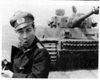
- All systems go - the Tiger ready for the final battle....jpg (36.75 KiB) Viewed 7219 times
Back On The Road Again...
Well, It's been a while. How many times have I said that?
I suppose I could blame the job. I can definitely blame the family (sorry guys). Lacking a 'manshed' (they're called a 'shoffice' round here) I have to compete for room with what else goes on in this kitchen. [Update - we now have a shed!]
Not just cakes, I hasten to add (although there have been plenty of those for recent birthdays and school 'cake days') - but also some
serious model making. Since my two boys discovered the sweet taste of medals at Euromilitaire and IPMS last year (a gold and two bronzes between them) I have started to feel like the diorama equivalent of a Hollywood film producer (without the
schmoozing at Cannes I hasten to add). I bring on the Polyfilla, the paints, the airbrush, the old Verlinden ruined buildings and Tamiya kits still unbuilt from my childhood (which I sell them at the prices still on the box) - and they let loose with their wild imaginations.
It's great, believe me, except who has to
clean the airbrush, find the right shade of
dunkelgelb - not to mention that piece of plastic which has just bounced away along the floor provoking tears of rage from my 9 year old son...
Look, I'm not complaining, right?!
Actually, I'm also conveniently avoiding a far more mundane truth. And maybe I
am complaining just a little. Not about my long-suffering wife, or the boys - but about you lot. Didn't anyone notice my cry for help? Actually
lister fiend did - thanks buddy. It was headed
Taigen Recoil SOS.
It was an embarrassing problem, I have to admit. But men of my age (46) have to face up to these things from time to time. How should I put this? Er... my recoil wasn't working. OK it worked
sometimes. But not when it needed to work, OK? I had this problem for some time. I tried to sort it out but nothing seemed to make it right. So what did I do?
Well, I figured the problem had to be either my recoil unit - or my tank. I had a spare (new) Taigen unit so I tried that - no difference. So I took apart my son's HL Panther and rigged up the recoil to that. And it worked! As did the old one. Hmm...
So it had to be the tank. I looked and looked at my HL Tiger's upper hull and bottom and what did I find? I loose bloody wire, that's what!
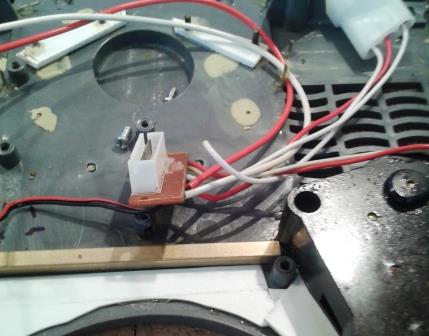
- The pesky loose wire which had meant my recoil unit worked intermittently for the last few months....jpg (32.78 KiB) Viewed 7219 times
My Tiger is ancient. An old RX15 model no less. And although I have replaced just about all of it, the upper hull has the original wiring. As those who have read this thread will know, I have tested this part to its limits: rewiring the headlight(s), the MG and the link to the turret. I had even moved back the eight-point socket which connects (almost) everything to the lower hull. In all of this I had never actually checked the wiring to the socket itself.
And therein lies a lesson. As I said way, way above, I am a virtual dunce when it comes to electronics, but I had always believed that one should 'follow that wire'. I didn't and the result was that I downed tools because I couldn't face doing even more detail on this Tiger knowing that I would have to keep turning it inside out trying to fix a problem I simply couldn't understand.
So, I fixed the problem by rewiring the 8-point socket and the recoil hasn't failed since. It’s great!
So what’s new?
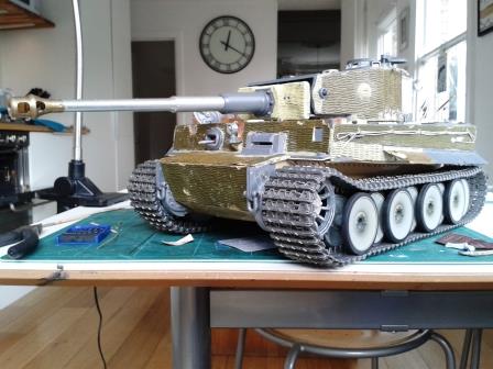
Well for a start the Tiger is back on the kitchen table. My eldest son, who was 8 when I started on ‘his’ tank, is excited again when the gun flashes and springs back before gliding elegantly back to its starting position (his kits don’t move) – and so am I. Now I can get back to what I love – what that wily old fox Belgian Francois Verlinden (remember him?) called ‘super-detailing’.
Barrel sleeve grub nuts
Great title, eh?
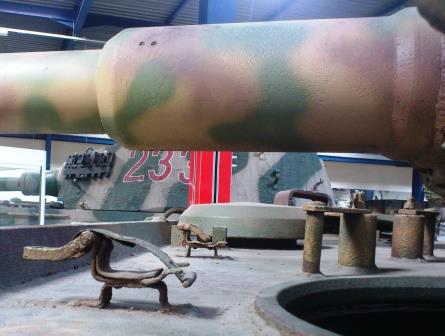
On the barrel sleeve (the bit attached to the mantlet) there were pairs of recessed grub nuts in the ten and two o’clock position (and possibly more beneath the barrel, but these can’t be seen). They are small, you can’t see them in most contemporary photos and they won’t keep you awake at night if you miss them – but they are there all the same.
I decided to wrap some Tamiya masking tape round the barrel sleeve (this is great, low-tack tape) so I could use a pen to draw the locations without the glare from the plastic. Having done this (by eye) I drilled the holes right through.
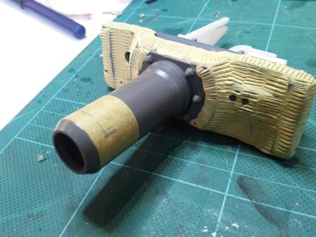
- Tamiya masking tape around the barrel made it easier to mark the location of the screws.jpg (32.15 KiB) Viewed 7219 times
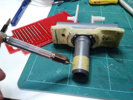
- The screw holes were then made with a fine drill.jpg (32.6 KiB) Viewed 7219 times
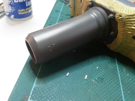
- Lastly the screws themselves were inserted using short lengths of plastic rod - slightly recessed like the originals.jpg (25.81 KiB) Viewed 7219 times
Short pieces of plastic rod were then inserted into the holes with liquid glue and slightly recessed to give the appropriate look. David Parker (of AFV Modeller fame - mentioned above) actually slotted the screw heads before he did this, but for me this is going too far!
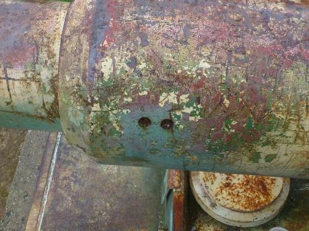
- Close up of the grub nut holes on the Vimoutiers Tiger.jpg (43.89 KiB) Viewed 6789 times
- The grub nuts on the barrel of the Saumur Tiger and other interesting details.jpg (31.02 KiB) Viewed 6789 times