Thanks Barry,
RiskyR wrote: ↑Wed Jan 04, 2023 6:37 pm
The attention to detail is absolutely amazing. What makes it even better is that everything works as well! Superb!

Thanks, yes, this build was stressful, i never know exactly how its going to turn out. Potential mistakes can be made at every construction steps. I do have a lot of experience with building AFV with interiors (four M-113, Marder 1A1, BMP-1) but the rotating basket is always a challenge, and the limited space left for the electronics is also very restricted. Thankfully, the Bradley is a large vehicle. The satisfaction was high when i saw that turret basket rotating...
I am in the final stages of construction
Next are the side skirts.
As seen in the Sabot book on M2A3, the side skirts are covered with attachment points for crew and soldiers personal equipment. There are 4 types of attachments (1 to 4 points). I used the graph below for instructions as to which ones go where. But i have a feeling it is up to the crew to decide which ones they want to put on their tanks and at what location.

- M3A3 Bradley US Cavalry Fighting Vehicle - RC 1/16 Build
- Capture.JPG (176.38 KiB) Viewed 944 times
The kit provides more than enough attachments of each types for any configuration. Below is the sprue with the 4 points. A few are defective but it does not matter because about only half are used.

- M3A3 Bradley US Cavalry Fighting Vehicle - RC 1/16 Build
- Capture0.JPG (233.76 KiB) Viewed 944 times
I decided to attach them with M1 x 4 and M1 x 6 brass bolts with washers. I had hundreds of these bolts on inventory when i started the build and it used all of them, i just barely had enough.

- M3A3 Bradley US Cavalry Fighting Vehicle - RC 1/16 Build
- Capture1.JPG (310.16 KiB) Viewed 944 times
The attachments on the bottom row we given a 6mm long bolt because they are the ones holding the skirts against the upper hull. I small hole was drilled all the way through the upper hull cover in order for the bolts to screw into the hull and keep the skirts solidly in place. If needed, the skirts are removable. Not sure what kind of glue could have been used to glue the 3D printed skirts against the hull but i determined i did not have any glue that could have done the job. There is something about 3D SLA part that sometimes is impossible to glue, no matter how much or how long you take.

- M3A3 Bradley US Cavalry Fighting Vehicle - RC 1/16 Build
- Capture2.JPG (71.52 KiB) Viewed 944 times
Of course, any one using hex brass bolts need the screwdriver that goes with each bolt head size. Knupfer of Germany is my preferred seller.

- M3A3 Bradley US Cavalry Fighting Vehicle - RC 1/16 Build
- Capture3.JPG (204.88 KiB) Viewed 944 times
The completed side skirts are installed. The Combat Identification Panel (CIP) is hanged there just for display purposes. They are not installed yet.
The model is very heavy, currently at 9.5 pounds fully loaded. Its not just the metal tracks, all that extra armor adds up like the real thing. I am noticing the suspension is having a hard time despite augmenting the size of the torsion bars on 3 rows. I will have to change the torsion bar on the remaining two middle rows of wheels, and maybe give more torques on the others. Looks like the model could be 3mm too low right now. In any cases, the torsion bars that came with the kit were way too weak, even without any mods.

- M3A3 Bradley US Cavalry Fighting Vehicle - RC 1/16 Build
- Capture4.JPG (158.67 KiB) Viewed 944 times
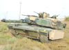
The vehicle construction is mostly completed. Here is a walking around with some close ups, notice it is dusty. And i am noticing i missed one attachment at the bottom left.

- M3A3 Bradley US Cavalry Fighting Vehicle - RC 1/16 Build
- Capture5.JPG (141.05 KiB) Viewed 944 times

- M3A3 Bradley US Cavalry Fighting Vehicle - RC 1/16 Build
- Capture6.JPG (141.62 KiB) Viewed 944 times

- M3A3 Bradley US Cavalry Fighting Vehicle - RC 1/16 Build
- Capture6b.JPG (111.37 KiB) Viewed 944 times

- M3A3 Bradley US Cavalry Fighting Vehicle - RC 1/16 Build
- Capture7.JPG (182.57 KiB) Viewed 944 times
Continuing on following post