Continuing with part 2.
These are the part that were prepared for the mount, all scratch. Some more small details will be added later at the end of the build so that they do not get damaged during manipulation.
 Viewed 4205 times")
- M-113 Tow missile mounting
It is important to figure out a system where the TOW launcher will be solidly in place, while still allowing the roof of the vehicle to be raised. This section is glued to the floor and central pole.
 Viewed 4205 times")
- M-113 Tow missile mounting
What I interpreted as an anchor mechanism is reproduced on the floor. This area is quite vague in all references so I kept it to a minimum.
 Viewed 4205 times")
- M-113 Tow missile mounting
The mount can be raised and lowered but won't make much use of it, it is mostly for the look.
 Viewed 4205 times")
- M-113 Tow missile mounting
This is the gunners platform, fixed at that level.
 Viewed 4205 times")
- M-113 Tow missile mounting
The complex plate at the top of the pole was split in half so that the front section is glued to the rails and central pole, the other half is glued to the roof and it keep the central pole solidly locked in sandwich. When the vehicle will move, the heavier resin launcher will not force against the base of the pole. The roof is removable of course and the height of the missile luncher can be adjusted. Removing the roof involves a careful raising and turning of the roof around the missile launcher within the top latch, without touching it.
 Viewed 4205 times")
- M-113 Tow missile mounting
Rear view of the mount and gunners platform. At one point, I will place the wiring, one set going to the control box on the left, one set going to the battery on the right.
 Viewed 4205 times")
- M-113 Tow missile mounting
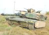
View of the exterior of the M-113A2 with TOW launcher installed, likely a rare sight in 1/16 scale RC, with detailed interior.
 Viewed 4205 times")
- M-113 Tow missile mounting
 Viewed 4205 times")
- M-113 Tow missile mounting
 Viewed 4205 times")
- M-113 Tow missile mounting
Next step is the TOW missile rack on the right, and the buildup of the TOW missile inventory.
Regards, Louis