Page 1 of 2

ELmod IR Battle Wiring

Posted: Thu Mar 15, 2018 2:38 pm
by Yojo
Hi All,

I am currently working with a few ELmods (three in total),

I have managed to get everything working fine and functional, but I am stuck with the IR Battle connection, I know you can buy an adaptor from ELmod for all popular systems, but as I am a dab hand with a soldering iron and wiring I thought I would just make my own and all would be fine.

What I'm struggling with is getting the pin-outs right as ELmod uses 5 pins and doesn't really give me the orientation for pin 1 on any diagrams I have access too, what I know so far is,

ELmod pin-outs

1 - VCC
2 - TX_IR
3 - GND
4 - RX_TSOP
5 - LED

Clark Pin-outs

Apple pin-outs
1 - TBU +
2 - TBU SIG
3 - TBU -
4 - TBU FLASH LED -
5 - TBU FLASH LED +


IR Emitter pin-outs
1 - IR LED +
2 - IR LED -


So working from these pin-outs, ELmod are using a shared + on pin 1, so I have wired as below.

1 - VCC - (1 - TBU +)( 5 - TBU FLASH LED +)(1 - IR LED +)
2 - TX_IR - (2 - IR LED -)
3 - GND - (3 - TBU -)
4 - RX_TSOP - (2 - TBU SIG)
5 - LED - (4 - TBU FLASH LED -)

Does this look correct? am I missing something? or am I just being over cautious?

Any input welcome
Cheers All
Re: ELmod IR Battle Wiring

Posted: Thu Mar 15, 2018 7:07 pm
by wibblywobbly
This is what I have in my trusty pile of scribbled scrap paper, which seems to match yours precisely. :thumbup:

1. Vcc/IR LED+/Hit LED+
2. IR LED-
3.GND
4. Out (SIG)
5. Hit LED-

Re: ELmod IR Battle Wiring

Posted: Sun May 13, 2018 5:35 pm
by minimivic
Doing a little work to add an IR battle system today and I'm getting a little stuck.

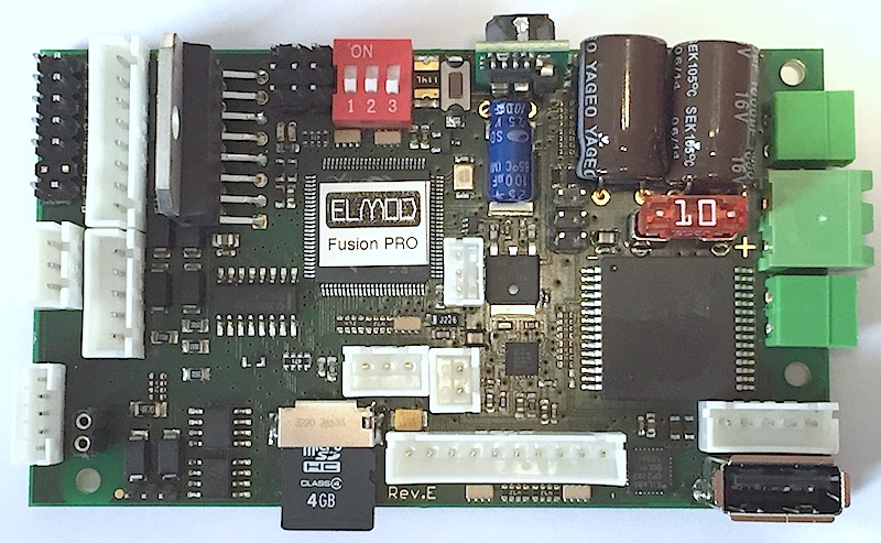
I have elmod revision e board Image
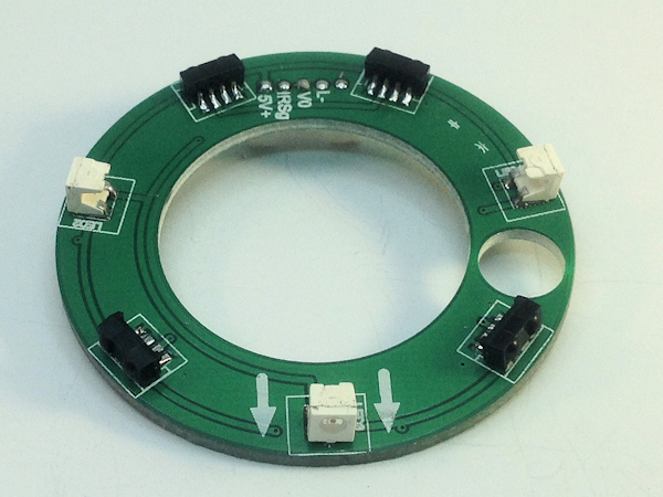
and a Tiger ring Image

On the elmod the ir battle connector is the 5 pin white block lower left of the picture, now Pin 1 should be the top pin as pictured and pin 5 the lower pin closest to the outside ( i think)

Now according to the above and me
1. Vcc/IR LED+/Hit LED+ Tiger ring 5v+
2. IR LED- Tiger ring N/C
3.GND Tiger ring Vo
4. Out (SIG) Tiger ring IRsig
5. Hit LED- Tiger ring L-

Then i guess for the IR emitter I use the 5V+ and the IR LED-

Can someone check my logic,

Thanks

Re: ELmod IR Battle Wiring

Posted: Sun May 13, 2018 6:30 pm
by wibblywobbly
You got it, pins 1 & 2, the emitter shares the circuit, so the Elmod only uses the 5 pin plug, rather than having a separate 2 pin plug for the emitter.

Yojo description:

1 - VCC - (1 - TBU +)( 5 - TBU FLASH LED +)(1 - IR LED +)
2 - TX_IR - (2 - IR LED -)
3 - GND - (3 - TBU -)
4 - RX_TSOP - (2 - TBU SIG)
5 - LED - (4 - TBU FLASH LED -)

Which is:

IR emitter (+) is pin 1.
Hit led (+) is pin 1
Sensor VCC is pin 1.

IR emitter (-) is pin 2.

Sensor GND is pin 3.
Sensor SIG is pin 4.

Hit led (-) is pin 5.

You can't blow anything up, an led only works if the +/- are the right way around, it doesn't blow if it is the wrong polarity.
The sensors seem to be immune to damage, I used to get them wired wrong all the time without any issues.

Re: ELmod IR Battle Wiring

Posted: Sun May 13, 2018 6:52 pm
by minimivic
Shame it doesn’t work though.
Need to try again.

Re: ELmod IR Battle Wiring

Posted: Sun May 13, 2018 6:57 pm
by wibblywobbly
You can check the IR emitter with a phone camera, just fire the gun with the lens pointed at the led, you can't see IR with a naked eye, but you will see it on the camera screen.

Which parts of the system aren't working?

Re: ELmod IR Battle Wiring

Posted: Sun May 13, 2018 8:22 pm
by minimivic
I haven’t connected an emitter yet, haven’t got a spare here at the moment.
I tried the test function in the pc software and dip switch to see if I got hit led working, but nothing happens.i tried a few remotes.

Re: ELmod IR Battle Wiring

Posted: Sun May 13, 2018 8:26 pm
by wibblywobbly
I only just noticed that the sensors have 4 legs instead of three? I have never seen those before. Did the ring come with a circuit diagram telling what the pins are?

Re: ELmod IR Battle Wiring

Posted: Sun May 13, 2018 9:02 pm
by minimivic
when I meter the Tiger ring out:
5v+ connects to one side of LED and one of the middle pins on the Sensor
IRsig connects to the other one of the middle pins on the Sensor
V0 connects to both the outer pins on the sensor
L- connects to the other side of the LED
the 5th pin goes nowhere N/C

Re: ELmod IR Battle Wiring

Posted: Sun May 13, 2018 10:34 pm
by wibblywobbly
Assuming that you have the same colours on your 5 pin Elmod plug.

Red
Sensor VCC 5v (Marked as 5v on turret ring)
IR Emitter + (Long Leg)
Hit LED + (Long Leg)

Blue (Marked as L - on turret ring)
IR Emitter -(Short Leg)

Black
Sensor V0 GND (Marked as V0 on turret ring)

Green
Sensor SIG (Marked as IR SIG on turret ring)

Yellow
Hit LED - (Short Leg)