Converting a 'Static' Kit to RC...
Posted: Sun Dec 08, 2013 3:02 pm
I am Finally getting around to converting an HM Armed Forces 'Tank' that is a purely push along Static childs toy into an RC version for my 5 year old son.... I bought the model from 'Rocketman' much too long ago ( sorry about the delay  )...So all the credit goes to him for the turret.
.
)...So all the credit goes to him for the turret.
.
I came to the usual problem of 'mounting the motors' in the hull.........?...... I am a great fan of using metal bolts to secure the drive train to these models...so I then ran into the problem of how to locate the mounting holes in the correct place in the hull. Yes you can try to hold the motors in the right place and try to mark the holes but it is a bit unreliable and some of the holes are very difficult to reach through the gears.
.
So this is my method and it seems to work.
.
If you have a scanner to go with your computer, then you have a photocopy facility. So enlarge the holes that you want to use in the mounting plate of the gearbox and then carefully place it on the glass...and make a photocopy of it.
Cut the copy out to exactly the size of the mounting plate..... ( If needed, get an 'adult' to help you with the sharp scissors ) Turn it the printed side up and use a 'Punch' to take out the mounting holes.
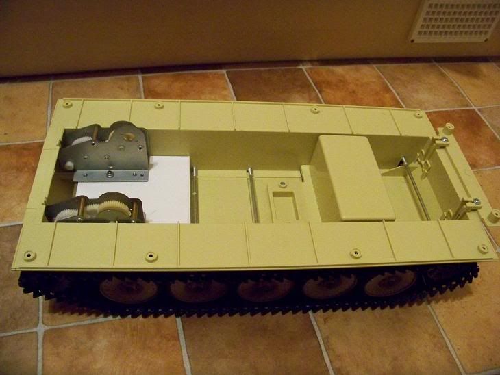
Carefully manoeuvre the gear box into the correct position on the hull floor trying to hold the paper template underneath it .(bearing in mind that the sprocket must end up in the centre line of the road wheels)
) Turn it the printed side up and use a 'Punch' to take out the mounting holes.
Carefully manoeuvre the gear box into the correct position on the hull floor trying to hold the paper template underneath it .(bearing in mind that the sprocket must end up in the centre line of the road wheels)
Once the gear box is in the right place the 'template' can be gently moved about with a screwdriver until the mounting holes line up perfectly between the gearbox mount and the template. Add a couple of drops of super glue to leading edge of the paper template and once dry remove the gearbox.
With any luck you should now be left with the template in the correct position. Use a soldering iron to 'melt' holes in the hull floor, this way you do not need to risk touching the template and it moving after all you hard work.
In THEORY....once the holes are drilled out...the gearbox should now fit in the correct place as per the 'Plan' 
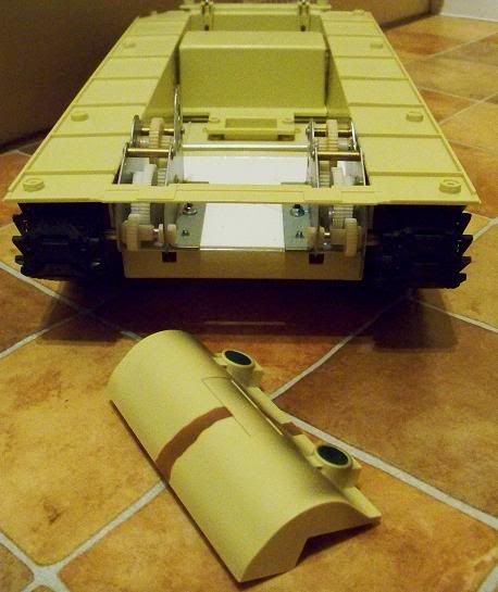
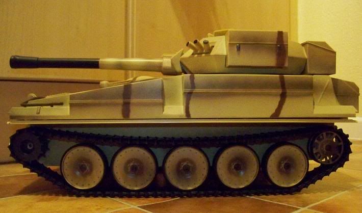
- All credit goes to Rocketman for the turret.....Only the 'plastic screwdriver' end is mine to approximate gun barrel length...
I came to the usual problem of 'mounting the motors' in the hull.........?...... I am a great fan of using metal bolts to secure the drive train to these models...so I then ran into the problem of how to locate the mounting holes in the correct place in the hull. Yes you can try to hold the motors in the right place and try to mark the holes but it is a bit unreliable and some of the holes are very difficult to reach through the gears.
.
So this is my method and it seems to work.
.
If you have a scanner to go with your computer, then you have a photocopy facility. So enlarge the holes that you want to use in the mounting plate of the gearbox and then carefully place it on the glass...and make a photocopy of it.
Cut the copy out to exactly the size of the mounting plate..... ( If needed, get an 'adult' to help you with the sharp scissors
- Photocopy of the bottom of the gearbox mounting plate.
- This is the 'photocopy' on the floor and the 'real' gearbox resting on its motor....They are of course the same size...
Once the gear box is in the right place the 'template' can be gently moved about with a screwdriver until the mounting holes line up perfectly between the gearbox mount and the template. Add a couple of drops of super glue to leading edge of the paper template and once dry remove the gearbox.
- I did not actually 'use' the bottom right hole that is marked in this photo