Scratchbuilding C&Cs Mammoth Tank


Re: Scratchbuilding C&Cs Mammoth Tank
It depends what Mammoth tank you are building I suppose, the true Mammoth tank from GDi would have probably followed American design and construction principles.
The Soviet part you are mentioning is from a parallel universe, a complete mess of a game, Red Alert.
If you look at the the other vehicles used by the GDi at the time, M113's, MLRS, Hummers, Abrams and Chinooks you will be looking at around about mid 90's.
Difficult about the main guns, could always scale them down slightly, 120mm ID with a thicker barrel. Perhaps they have large propellant charges that made this necessary? Two 120mm main guns with that length of barrel would provide some fearsome kick. Most of the larger calibre weapons tended to come from land based arty rather than naval.
It is never just "one" tank!
Re: Scratchbuilding C&Cs Mammoth Tank
Wow Blake, what's that picture of? And who made them? That's so close to the end result I want I'd really love to see more pics if there are any!
Re. the rest, maybe generators and motors may be a good idea? If they provide a better power:weight ratio then it certainly makes sense so I'll throw that into the pot while I continue to cook me a Mammoth pie
As for the origin of the Mammoth, where did you get that info from LMN? I'm looking now to try and find where I have it down as being a Soviet project but I'm not really finding very much history at all! Based on what I have found you may be right as it seems to be a GDI development in the original game.
Just found the following on origins of the mammoth in both games;
That indicates that it was a Western development after all which is very odd. Of course as LMN says, Red Alert is set in an alternate timeline when Hitler is killed before rising to power and Russia instead becomes the enemy of the West so perhaps I'm only remembering the history from that game?
Let's crunch some dates and get to the bottom of this... The first Command & Conquer game 'Tiberian Dawn' is set between 1999 and 2002 and in this timeline, Russia becomes allied with the West towards the end of WW2 (we won't mention the cold war :p)
In contrast, Red Alert is set in the 1950's and as quoted above, Stalin personally orders it's development to commence at this time under Soviet engineers.
To me that says everything. In a world where Hitler was never in power and Russia didn't face the crushing losses of WW2, Stalin possesses a far stronger nation than he does in the 'real-life' timeline of Command and Conquer (that parallels our own until the 90's) In the 50's he decides Europe is ripe for the taking with the Eastern states as weak as always, Germany weakened by infighting following Hitler's 'disappearance' and France as always being cheese-eating surrender-monkeys Russia mobilises for the Great World War II and invades the West, developing a vast array of new super-weapons including the superheavy Mammoth Tank.
Alternatively... In a 'normal' timeline Stalin's plans for conquest of the West are cut short when Hitler's own plans for domination begin to unfold. Plans for weapons such as the Mammoth tank remain dormant while Russia and Germany battle relentlessly on the Eastern front causing massive amounts of both financial and personnel losses to the USSR. At this point, the C&C timeline begins to differ from our own as the Global Defence Initiative is born (the GDI are the good guys!)
Correct me if you think I'm wrong but all of the above is based on official timelines and origin Wikis! Everything that isn't in quotemarks is in my own words so feel free to challenge it
I also found a few nice little exerpts from various sources this morning while writing this response. Checkthis out;
I've come to a decision regarding this and I need to crunch some numbers that I currently can't find to determine once and for all how large this gun may have been. The Medium tank in this game is equivalent to an Abrams and therefore the damage dealt by that main cannon is also comparable to the Abrams. Now considering that a single shot from the mammoth deals considerably more damage than a single shot from the medium tank we can deduce that they are NOT the same calibre weapon. Sadly I can't find damage statistics of either one right now (though I did find the Medium tank's yesterday) Both vehicles took part in the games 'Renegade' and the original 'Tiberian Dawn' so my mission for today is to put this calibre thing to bed once and for all!
Wish me luck
EDIT : Forgot to link a few images I found that are great comparison shots I've only just found! I hope I'm not too far off with my measurements :p

And a little model!!!

Re. the rest, maybe generators and motors may be a good idea? If they provide a better power:weight ratio then it certainly makes sense so I'll throw that into the pot while I continue to cook me a Mammoth pie
As for the origin of the Mammoth, where did you get that info from LMN? I'm looking now to try and find where I have it down as being a Soviet project but I'm not really finding very much history at all! Based on what I have found you may be right as it seems to be a GDI development in the original game.
Just found the following on origins of the mammoth in both games;
During the First Tiberium War the Brotherhood of Nod discovered a GDI facility near Mzuzu, Tanzania helping to develop the Mammoth tank.
That indicates that it was a Western development after all which is very odd. Of course as LMN says, Red Alert is set in an alternate timeline when Hitler is killed before rising to power and Russia instead becomes the enemy of the West so perhaps I'm only remembering the history from that game?
So now we see that the Russians develop it in the timeline where Hitler is no longer a threat...Acting on the orders of Joseph Stalin, Soviet engineers created the Mammoth Tank, the heaviest tank ever produced in that conflict.
Let's crunch some dates and get to the bottom of this... The first Command & Conquer game 'Tiberian Dawn' is set between 1999 and 2002 and in this timeline, Russia becomes allied with the West towards the end of WW2 (we won't mention the cold war :p)
In contrast, Red Alert is set in the 1950's and as quoted above, Stalin personally orders it's development to commence at this time under Soviet engineers.
To me that says everything. In a world where Hitler was never in power and Russia didn't face the crushing losses of WW2, Stalin possesses a far stronger nation than he does in the 'real-life' timeline of Command and Conquer (that parallels our own until the 90's) In the 50's he decides Europe is ripe for the taking with the Eastern states as weak as always, Germany weakened by infighting following Hitler's 'disappearance' and France as always being cheese-eating surrender-monkeys
Alternatively... In a 'normal' timeline Stalin's plans for conquest of the West are cut short when Hitler's own plans for domination begin to unfold. Plans for weapons such as the Mammoth tank remain dormant while Russia and Germany battle relentlessly on the Eastern front causing massive amounts of both financial and personnel losses to the USSR. At this point, the C&C timeline begins to differ from our own as the Global Defence Initiative is born (the GDI are the good guys!)
As a member of the Allied forces at the time when the GDI was formed, we must assume that all nations contributed funding, personnel and technology to the cause. As Russia had little to offer in the way of the former 2 options, the Mammoth project and other unfinished plans were thrown into the pot and GDI acquired the early plans for this beast. With little funding and no immediate requirement for the completion of the Mammoth tank, GDI forces continued to operate as a covert strike force for the next 40 years with no need for super-heavy or even heavy units. As situations in the world changed so did GDI;The concept of the organization had first been proposed within the United Nations Security Council by representatives of Allied countries amidst the 20th century's Second Great War,[2][3] and was in the aftermath of that conflict jointly established by unspecified numbers of the Council's members as a specialized, peace enforcing unit with a mandate to operate worldwide.
And so in 1995 development of many new weapons systems commenced and by 1999 (the First Tiberium War or TWI) the Mammoth tank was in the final stages of development. Hostile intervention prevented the tank from reaching the battlefield for some time but eventually the monster was unleashed on the enemies of GDI in the hands of the good guysThe organization was restructured and was brought out of the shadows, in order to make it capable of tackling the threats of the modern ages openly as well as directly. In accordance with the United Nations Global Defense Act (UNGDA), the United Nations' Global Defense Initiative (UNGDI) was founded at the date of October 12th 1995. The proposal stated the following:
"The Global Defense Initiative was founded to enforce the United Nations Global Defense Act and uphold the ideals as outlined in the United Nations Charter."[1
Correct me if you think I'm wrong but all of the above is based on official timelines and origin Wikis! Everything that isn't in quotemarks is in my own words so feel free to challenge it
I also found a few nice little exerpts from various sources this morning while writing this response. Checkthis out;
The tank was kept in working condition by an engineering crew inside, allowing it to repair to 50% of its strength.
The only thing that continues to frustrate me is the calibre of these cannons as EVERY official source states that they're lousy 120mm cannons. I'm sticking by the fact that no self respecting super-heavy battle tank would use such miniscule weaponry... And also the fact that the ingame 3D model has barrel sizes FAR in excess of this size (that's the size that the 11" is based off in fact)An atomic generator powers the enormous vehicle.[3] Mammoths are also equipped to independently carry out limited battlefield repairs.
I've come to a decision regarding this and I need to crunch some numbers that I currently can't find to determine once and for all how large this gun may have been. The Medium tank in this game is equivalent to an Abrams and therefore the damage dealt by that main cannon is also comparable to the Abrams. Now considering that a single shot from the mammoth deals considerably more damage than a single shot from the medium tank we can deduce that they are NOT the same calibre weapon. Sadly I can't find damage statistics of either one right now (though I did find the Medium tank's yesterday) Both vehicles took part in the games 'Renegade' and the original 'Tiberian Dawn' so my mission for today is to put this calibre thing to bed once and for all!
Wish me luck
EDIT : Forgot to link a few images I found that are great comparison shots I've only just found! I hope I'm not too far off with my measurements :p
And a little model!!!
Re: Scratchbuilding C&Cs Mammoth Tank
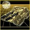
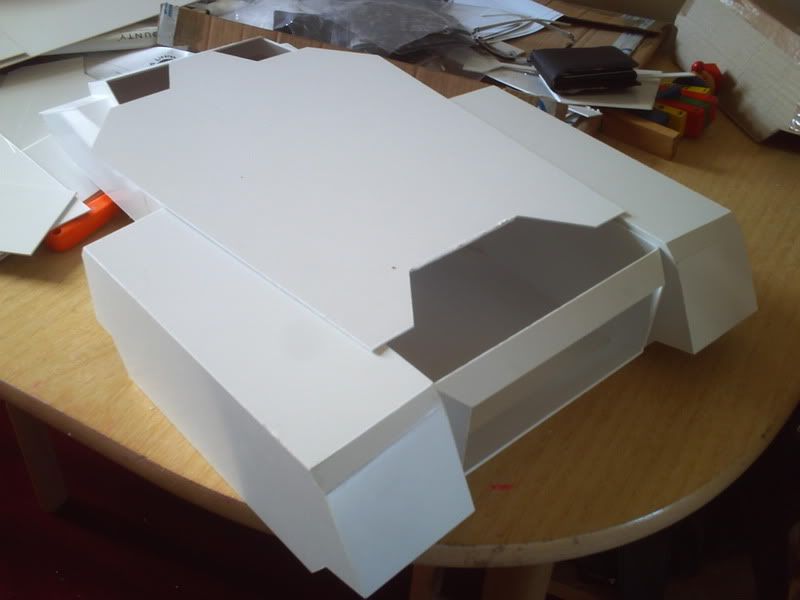
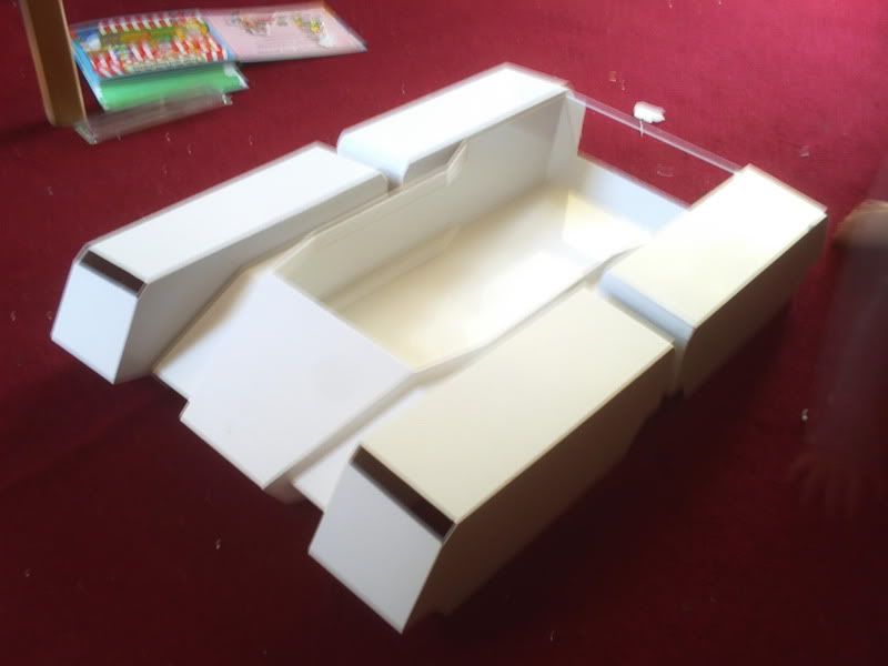
Not much of a post today and I'm still behind where I wanted to be but only slightly now I'm happy to say! I now have 2 tracks finished and all 6 of the big pieces cut for the other 2. That leaves 8 more smaller bits to finish off all 4 nut I'll probably get that done tomorrow now. Anyway here are a few pics from various angles with 2 finished pieces, gives the best idea of size and shape so far.
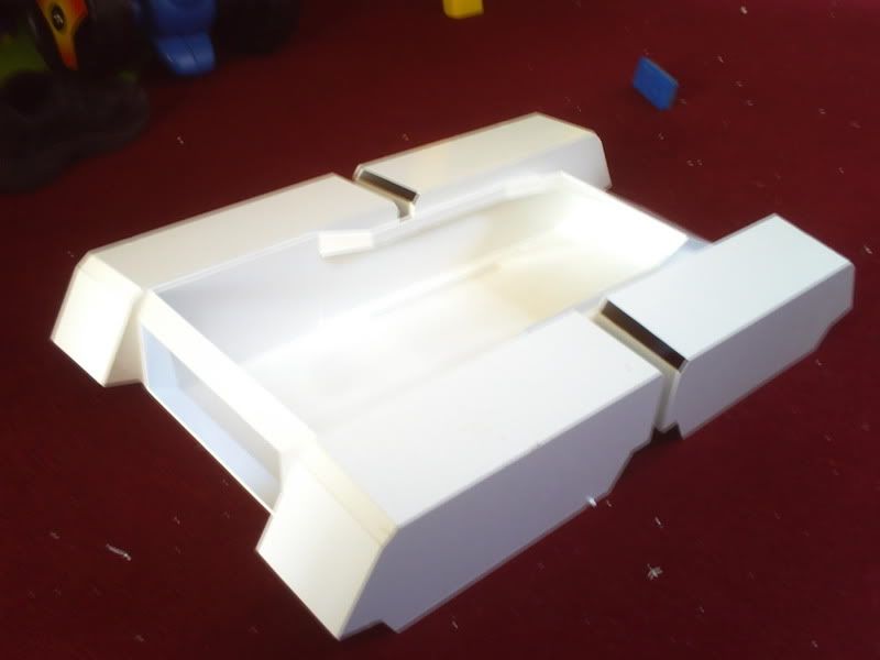
And a last shot of the nice little mesh I managed to get for the rear grill (which went in the post today) I got it from a £1 kitchen sieve and it should do the job nicely. Under the mesh are the big pieces of the two tracks that still need building.
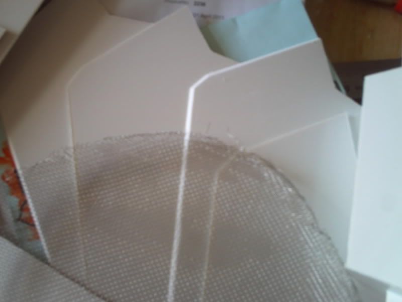
Will update again when I've got the grill in and all 4 tracks finished so it'll depend on the mail! My next pondering involves whether I should permanently attach the tracks to the hull (ie. glue 'em on) or whether there would be any benefit to keeping them removable by using screws or bolts or whatever... Can't remember why I first starting pondering this but I can't think of any viable reason not to permanently attach them as of right now
And a last shot of the nice little mesh I managed to get for the rear grill (which went in the post today
Will update again when I've got the grill in and all 4 tracks finished so it'll depend on the mail! My next pondering involves whether I should permanently attach the tracks to the hull (ie. glue 'em on) or whether there would be any benefit to keeping them removable by using screws or bolts or whatever... Can't remember why I first starting pondering this but I can't think of any viable reason not to permanently attach them as of right now
Re: Scratchbuilding C&Cs Mammoth Tank
Premature posting today as my grill hasn't arrived (not surprised as it's coming some distance!) but I have pretty much finished all 4 tracks! Still waiting on another box of parts before I decide on a solution for the track itself but for now at least I almost have the first layer of armour together!
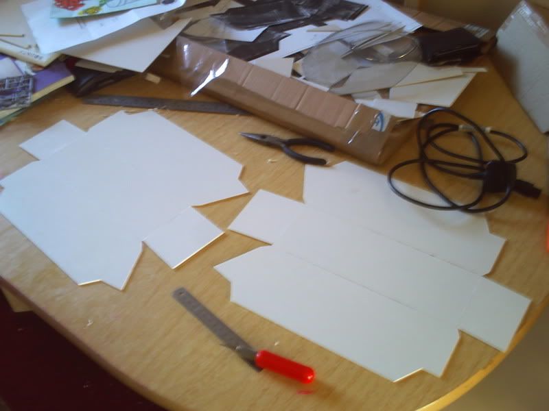
For the 2 I've done today I decided to cut the 4 smaller pieces (per side) separately as none of the ones I've done so far have been perfect fits when cut before assembly. For that reason, the small pieces are currently missing but regardless I'm still pretty chuffed with the grand scale of this thing now it can be seen in all it's glory!
The only thing missing now is a little height from the tracks (probably less than an inch) and the full length of the cannons which will add about 20-30cm onto the overall length of the vehicle. I have no idea how high the turret will be but it's not too tall thankfully as noone wants to be riding in an easy target, no matter how thick the armour is...
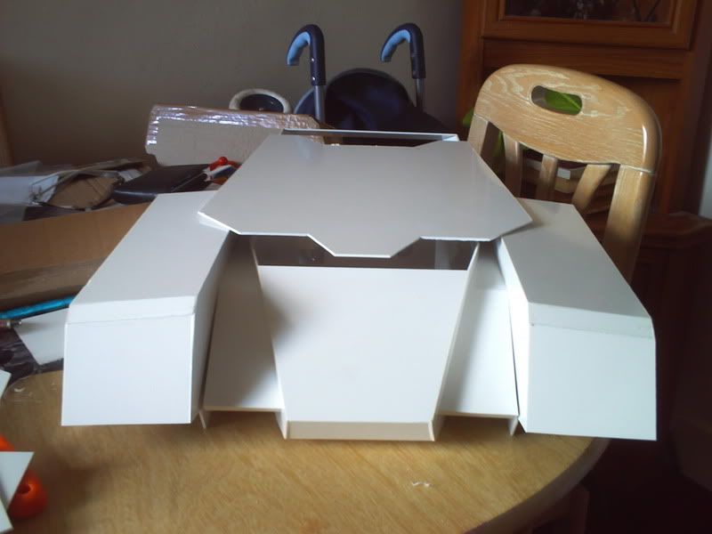
So here are the pieces pre-assembly - you'll be pleased to note there aren't many images today as the process has been seen already!
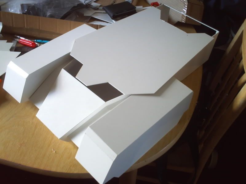
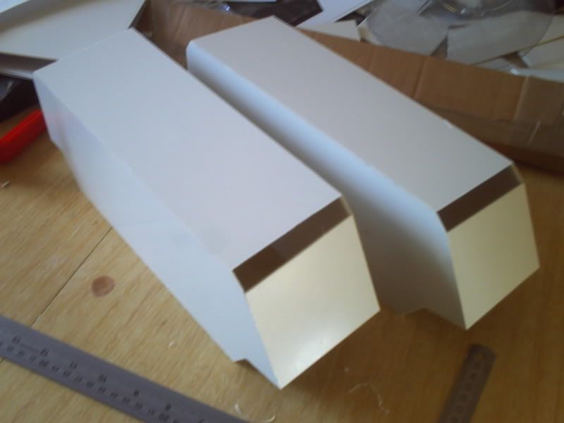
And post assembly
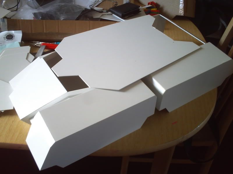
Now some shots of it all together (but not fixed) It no longer fits on the small desk where it was living and the table is covered with rubbish so it went on the floor for these shots!
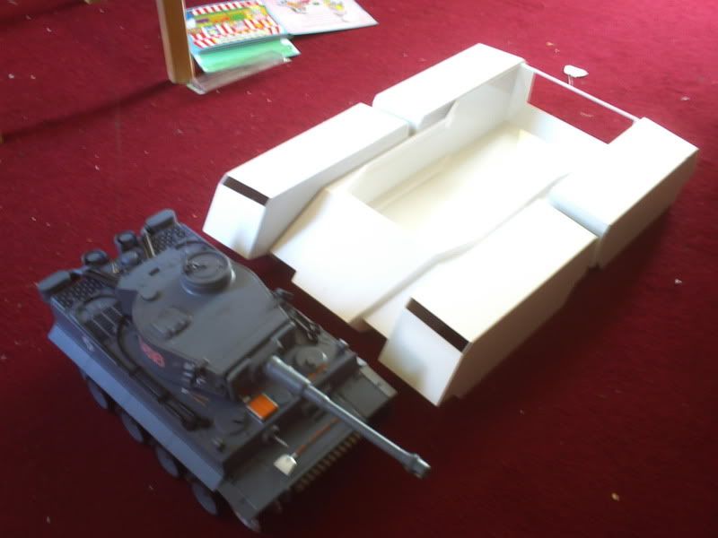
And finally some comparison shots to put it back into perspective. Here it is about to crush my poor little Tiger tank - though sadly the extensive track armour would prevent such a manoeuvre...
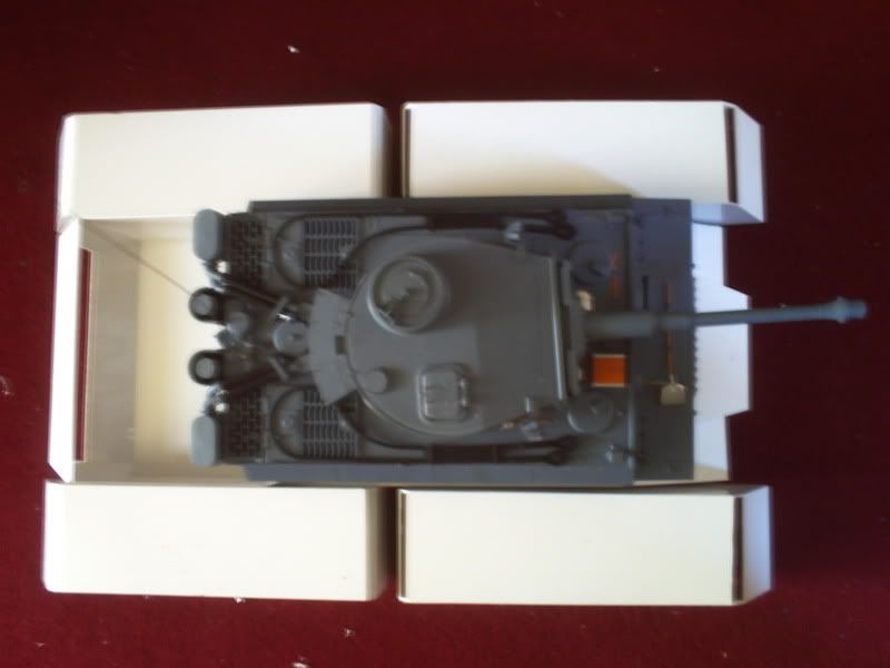
And here's another one with a makeshift turret, it seems to have swallowed something!
I just need to finish off the last 4 small pieces now which I'll probably do at the same time as the grill (depending on how long it takes to arrive) I'm now back to the original problem of how to allow access inside the tank once everything is finished but I have to cut the top pieces at some point so will do that soon as well. That means it's time to start thinking about how much weight will be in the turret and how I can support it and allow full rotation (360 would be nice!)
For the 2 I've done today I decided to cut the 4 smaller pieces (per side) separately as none of the ones I've done so far have been perfect fits when cut before assembly. For that reason, the small pieces are currently missing but regardless I'm still pretty chuffed with the grand scale of this thing now it can be seen in all it's glory!
The only thing missing now is a little height from the tracks (probably less than an inch) and the full length of the cannons which will add about 20-30cm onto the overall length of the vehicle. I have no idea how high the turret will be but it's not too tall thankfully as noone wants to be riding in an easy target, no matter how thick the armour is...
So here are the pieces pre-assembly - you'll be pleased to note there aren't many images today as the process has been seen already!
And post assembly
Now some shots of it all together (but not fixed) It no longer fits on the small desk where it was living and the table is covered with rubbish so it went on the floor for these shots!
And finally some comparison shots to put it back into perspective. Here it is about to crush my poor little Tiger tank - though sadly the extensive track armour would prevent such a manoeuvre...
And here's another one with a makeshift turret, it seems to have swallowed something!
I just need to finish off the last 4 small pieces now which I'll probably do at the same time as the grill (depending on how long it takes to arrive) I'm now back to the original problem of how to allow access inside the tank once everything is finished but I have to cut the top pieces at some point so will do that soon as well. That means it's time to start thinking about how much weight will be in the turret and how I can support it and allow full rotation (360 would be nice!)
-
[ICE]monkey

- 2nd Lieutenant
- Posts: 2669
- Joined: Wed Sep 10, 2008 5:58 pm
- Location: pluckley ,ashford ,kent
Re: Scratchbuilding C&Cs Mammoth Tank
looing good , shes going to be a big girl
cliff
cliff
-
blimp

- Sergeant
- Posts: 738
- Joined: Sat Dec 11, 2010 12:29 am
- Location: Watford , NW Londonistan . U.K.
Re: Scratchbuilding C&Cs Mammoth Tank
Looking good Munty ! - Hold the weight down to less than a ton and you can try keeping the old RX 18 set up with 2 gearboxes ( simpler and much cheapness  ) - but for 4 working tracks , remember - it will need new esc's + another radio setup , as the increased current draw of the extra motors is bound to fry H/L's boards .
 I'm going away and have a lay down now . . . .
- - You can always put 4 gearboxes in , but disable 2 by taking out a shaft/gear - this will give you free idling 'bogies' - allowing you to try front or rear track set ups , to see how it handles and steers . It'll also leave you with an instant 'up grade' option if you want it .
to the bouncy room ! Yay !
Re: Scratchbuilding C&Cs Mammoth Tank
Haha thqanks guys, yes it is going to be biiig! It's odd as I'm still nervous to see the final result due to a few points at which she's looked way out of proportion. I'm confident it'll be fine as I'm scaling up a model that is perfectly fine in it's original form and I know I've done the maths right. Even so it's always a challenge being the first to do something I think :p
Blimp, please treat me as an RC noob! I have very little idea about how the systems even work, let alone what I'm going to need to do when it comes to making my own! I'd like to end up with all four tracks powered but to be honest that'll probably make it WAY too fast compared to the speed it should actually be able to realistically reach... As for steering, I guess the dimensions and sheer surface area of the tracks will make a complete turn about the origin a fairly difficult or impossible task but that would be an ideal solution really. You can't build a tank this size (in real life) without providing it with some way to maneouvre in tight spaces. This beast would need to turn on the spot quite frequently I imagine, even if it's just to speed up training time of the main guns as it's notoriously sluggish as far as tanks go...
Anyway I have 2 gearboxes on their way to me now but I couldn't tell you what they are until I have them in front of me. I got them with a big bundle of tracks so I'll be able to give some more info on that when it all arrives.
I cut one of the 3 top pieces of the hull this evening and think I've decided on a method of fixing but I don't have the materials yet. I'll post up my thoughts another day but my back hurts from too much PC tonight so this is me taking a break
Thanks for following this build guys, I assure you I'll make it worth the wait
Re: Scratchbuilding C&Cs Mammoth Tank
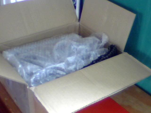
Time for another update sooner than I'd expected! Still no sign of the grill so not got new pics of the build today but I do have some images of my other delivery which is AWESOME by the way! The shipping on this stuff was horrendous but the joy of going through it all is like Xmas at Easter so it was worth it I guess!
Anyway I managed to find a guy with a whole bunch of tracks, wheels, gearboxes, you name it, but sadly right on the other side of the world... As I said, it's been crazy expensive but serious value for money (if only I had more of the latter, haven't even paid for these parts yet :s) Here is the haul I just signed for this morning and it's seriously a hell of a lot more than I was expecting! Prepare to be amazed at my new collection...
Big box! Though there's nothing here to compare it to so you have to take my word for it. You'll soon see how much was in it anyway
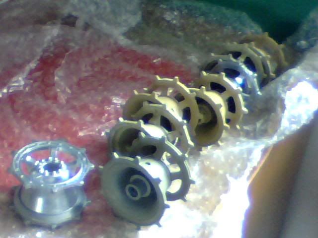
First thing to come out of it was a bunch of drive wheels, 8 of them to be precise! They're all metal which I wasn't expecting so they're heavier than I'd thought they would be but look very nice nonetheless! I later found another roll of these so I now have 18 matching drive wheels! That's 4 per track but it does at least give me more freedom on where to introduce the final drive to the track.
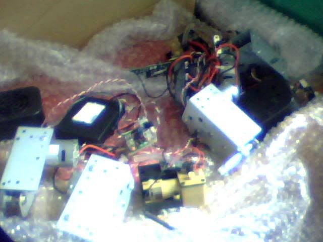
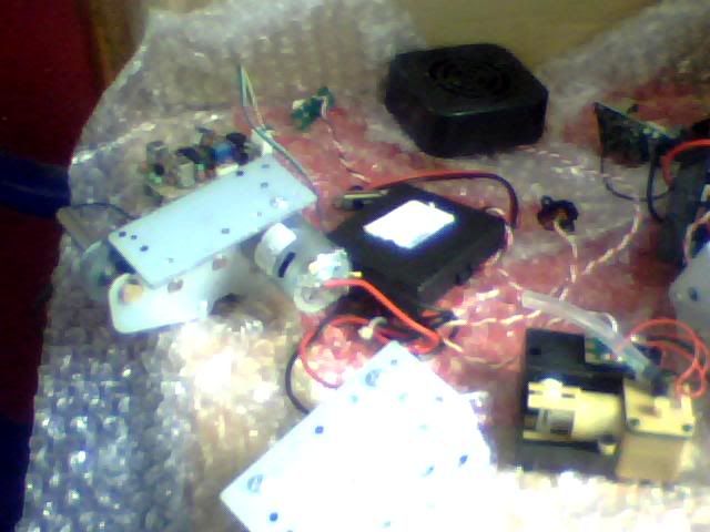
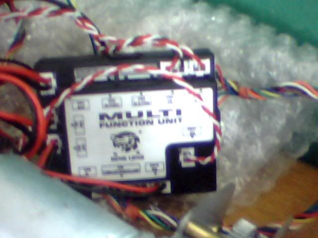
Now here's a massive pile of electronics, most of which I wasn't expecting and nearly all of which I can't describe! I believe there is smoke and sound there along with 4 gearboxes and some other bits and bobs. Please look at the images and tell me if you can make it out!
Here's one set pretty straightened out;
And a shot of a Heng Long bit that I now have 2 of in the other bundle;
Here's where it gets crazy mad though... I always said that making this project RC was my ultimate goal but either way it would need tracks. Here they are...
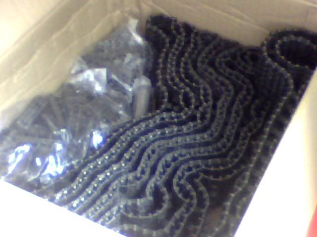
I now have 8 of these tracks which I believe are from a King Tiger? Here is one next to my puny normal Tiger track...
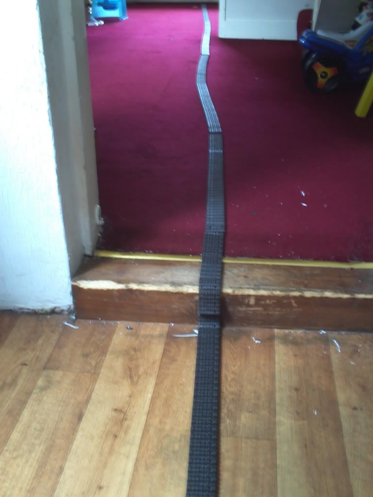
I wanted to give an idea of just how much track I now have so I laid it end to end and it reaches from the sitting room right through to the kitchen! I also have 2 bags of individual track segments and another bag of spare pins!
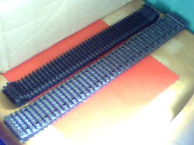
I already knew this was about 50mm wide track so I was absolutely certain it would look to narrow on the Mammoth but I took a look anyway. This is a single track from the King and it's about 40mm short of filling the full width of the armour.
I then laid another one half over it to show what I think looks like a good width. It's about 70-75mm and the space is just shy of 90mm wide.
So I've been sitting pondering what to do with this stuff and playing with some of the spare links to see what would be involved in widening the track. As it turns out, quite a lot! I figured out that each 73cm length comprises of 296 separate links. Now obviously to widen each piece I'll need two sections to make one, giving a total of almost 600 links per track. Over four tracks that would mean sitting down and nodifying almost 2,400 links to make the tracks as wide as I would like them!
Now I already know I have well over that as each of the 8 complete tracks I have is about 18 links longer than they need to be for the Mammoth but do I really want to spend that much time adding a mere 15mm to my track widths? Well... No... But I do want this to look right and it's going to need wider tracks for that to be true. So I've been experimenting and I came up with the below result as an initial prototype.
This is a fairly quick try at a very early solution and is still a bit narrow for my liking at just 67mm. The below image shows how it would look in place and I reckon there's at least another 8-10 mm to be had out of that.
Of course, I've already stumbled upon how difficult this would be and there are many more problems than just the obvious ones of time and labour. Of course strength is going to be an issue as essentially I'm just sticking an extra bit of track on the end of the original (though it's not that simple, I'm actually cutting one end off 2 pieces then joining them seamlessly in the middle) The pins are now ALL too short so I'd need to cut almost 300 new ones from the right gauge of wire, although next to 2,400 links that doesn't sound like too big a job!
The upside of needing the new pins is that the links would regain a lot of their strength once these are in place. It would ensure that there is no twisting or bending of the links and so help preserve the artificial join. Anotehr problem though is that I'll be left with a massive overhang of track on either the inside or outside of the drive wheel. These are approximately 35mm wide and if they were fitted with 70mm track there would be almost 25mm of new track that was basically attached to one side of the original piece.
Another problem which is purely cosmetic does result in the introduction of a third hole in each link (apologies if there's an official name!) This is obviously caused by the additional track being made from pieces that already have the holes in but it looks a bit crappy as it's clearly unnecessary so why is it there?
Thankfully... Writing this last piece has just given me a mini brainwave... What if that third hole was being used? Remember me saying I have twice as many drive wheels as I need? And I wanted the track about 70-75mm wide? Problem solved...
I think it may work with the right attention given to it. The narrow shaft between the outer rims would need widening to at least the diameter of the inner face there (with the bolts on) or it looks way too girlie to work in a real-life situation, other than that though it may have legs. Total track width is almost bang on 75 mm and it would help keep some strength in the construction by having that outer rim for support and a longer wire with the join more towards the centre of each link.
I may have a play later and try making up a few links for that setup, see how it looks/if it works! Let me know what you think, and don't worry I know it's very wierd so I'm not expecting anyone to tell me it's beautiful :p If there are any other ideas as to how I can make this work please let me know
EDIT : Turns out by using this method I can stagger the cuts every other link which will further improve rigidity. These links have male and female links as opposed to uniform ones so I can set the joins in different places on each type which might be nice
AND AGAIN : Made up a few links and it looks pretty good. It'll never be prefect though and will of course take me a million years to do the whole thing like this... So that begs the question, what do we know about molding parts? Any small companies in the world who could make me up 2 molds and crank out a few hundred of these puppies? Or better yet is there a way I can do it myself?
Anyway I managed to find a guy with a whole bunch of tracks, wheels, gearboxes, you name it, but sadly right on the other side of the world... As I said, it's been crazy expensive but serious value for money (if only I had more of the latter, haven't even paid for these parts yet :s) Here is the haul I just signed for this morning and it's seriously a hell of a lot more than I was expecting! Prepare to be amazed at my new collection...
Big box! Though there's nothing here to compare it to so you have to take my word for it. You'll soon see how much was in it anyway
First thing to come out of it was a bunch of drive wheels, 8 of them to be precise! They're all metal which I wasn't expecting so they're heavier than I'd thought they would be but look very nice nonetheless! I later found another roll of these so I now have 18 matching drive wheels! That's 4 per track but it does at least give me more freedom on where to introduce the final drive to the track.
Now here's a massive pile of electronics, most of which I wasn't expecting and nearly all of which I can't describe! I believe there is smoke and sound there along with 4 gearboxes and some other bits and bobs. Please look at the images and tell me if you can make it out!
Here's one set pretty straightened out;
And a shot of a Heng Long bit that I now have 2 of in the other bundle;
Here's where it gets crazy mad though... I always said that making this project RC was my ultimate goal but either way it would need tracks. Here they are...
I now have 8 of these tracks which I believe are from a King Tiger? Here is one next to my puny normal Tiger track...
I wanted to give an idea of just how much track I now have so I laid it end to end and it reaches from the sitting room right through to the kitchen! I also have 2 bags of individual track segments and another bag of spare pins!
I already knew this was about 50mm wide track so I was absolutely certain it would look to narrow on the Mammoth but I took a look anyway. This is a single track from the King and it's about 40mm short of filling the full width of the armour.
I then laid another one half over it to show what I think looks like a good width. It's about 70-75mm and the space is just shy of 90mm wide.
So I've been sitting pondering what to do with this stuff and playing with some of the spare links to see what would be involved in widening the track. As it turns out, quite a lot! I figured out that each 73cm length comprises of 296 separate links. Now obviously to widen each piece I'll need two sections to make one, giving a total of almost 600 links per track. Over four tracks that would mean sitting down and nodifying almost 2,400 links to make the tracks as wide as I would like them!
Now I already know I have well over that as each of the 8 complete tracks I have is about 18 links longer than they need to be for the Mammoth but do I really want to spend that much time adding a mere 15mm to my track widths? Well... No... But I do want this to look right and it's going to need wider tracks for that to be true. So I've been experimenting and I came up with the below result as an initial prototype.
This is a fairly quick try at a very early solution and is still a bit narrow for my liking at just 67mm. The below image shows how it would look in place and I reckon there's at least another 8-10 mm to be had out of that.
Of course, I've already stumbled upon how difficult this would be and there are many more problems than just the obvious ones of time and labour. Of course strength is going to be an issue as essentially I'm just sticking an extra bit of track on the end of the original (though it's not that simple, I'm actually cutting one end off 2 pieces then joining them seamlessly in the middle) The pins are now ALL too short so I'd need to cut almost 300 new ones from the right gauge of wire, although next to 2,400 links that doesn't sound like too big a job!
The upside of needing the new pins is that the links would regain a lot of their strength once these are in place. It would ensure that there is no twisting or bending of the links and so help preserve the artificial join. Anotehr problem though is that I'll be left with a massive overhang of track on either the inside or outside of the drive wheel. These are approximately 35mm wide and if they were fitted with 70mm track there would be almost 25mm of new track that was basically attached to one side of the original piece.
Another problem which is purely cosmetic does result in the introduction of a third hole in each link (apologies if there's an official name!) This is obviously caused by the additional track being made from pieces that already have the holes in but it looks a bit crappy as it's clearly unnecessary so why is it there?
Thankfully... Writing this last piece has just given me a mini brainwave... What if that third hole was being used? Remember me saying I have twice as many drive wheels as I need? And I wanted the track about 70-75mm wide? Problem solved...
I think it may work with the right attention given to it. The narrow shaft between the outer rims would need widening to at least the diameter of the inner face there (with the bolts on) or it looks way too girlie to work in a real-life situation, other than that though it may have legs. Total track width is almost bang on 75 mm and it would help keep some strength in the construction by having that outer rim for support and a longer wire with the join more towards the centre of each link.
I may have a play later and try making up a few links for that setup, see how it looks/if it works! Let me know what you think, and don't worry I know it's very wierd so I'm not expecting anyone to tell me it's beautiful :p If there are any other ideas as to how I can make this work please let me know
EDIT : Turns out by using this method I can stagger the cuts every other link which will further improve rigidity. These links have male and female links as opposed to uniform ones so I can set the joins in different places on each type which might be nice
AND AGAIN : Made up a few links and it looks pretty good. It'll never be prefect though and will of course take me a million years to do the whole thing like this... So that begs the question, what do we know about molding parts? Any small companies in the world who could make me up 2 molds and crank out a few hundred of these puppies? Or better yet is there a way I can do it myself?
Re: Scratchbuilding C&Cs Mammoth Tank
Success! As is often the way, a good night's sleep has given me some more thoughts which should make this possible and keep it pretty sturdy too. There are a load of images today but they were only taken with a webcam so they're smaller than usual. They show the changes I've made between yesterday's prototype and today's and also how far I've gone with the idea to enable a little bit of testing. Here they are anyway...
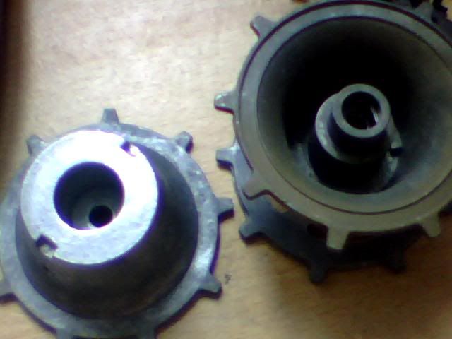
First brainwave I had was just dumb luck that I noticed something out of the corner of my eye whilst sat at this very computer and still in the process of waking up. My last update yesterday was how I thought of using a double wide drive wheel to engage the maximum amount of track possible but it would've needed some pretty major modifications to make it look sturdy.
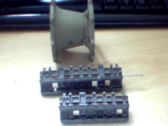
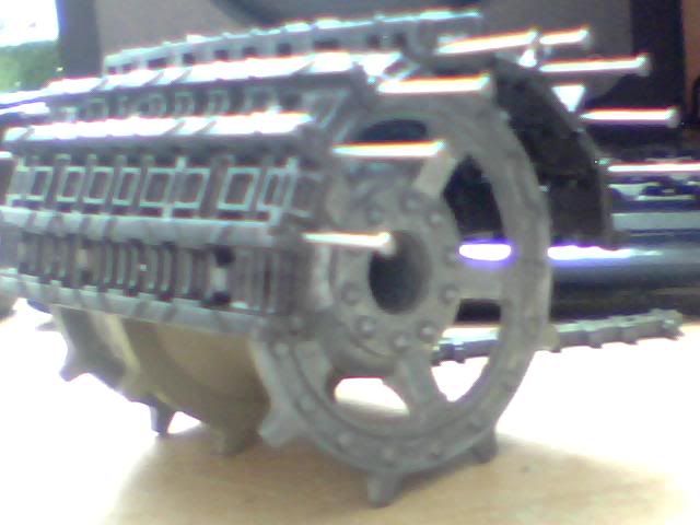
This morning I realised that I'd missed a trick but now I've caught up with myself here's the deal... Each of these drive wheels split in half, hence my ability to extend one full wheel with the face of another one. As I sat down this morning this trio of parts was sat staring me in the face and next to it was the unused rear of the second drive wheel I nicked the front off. Turns out you can very easily stack the rear parts of these drive wheels and they slot together perfectly with next to no movement! It also provides exactly the same additional distance between the 2nd and 3rd row of holes! Here's what I mean...
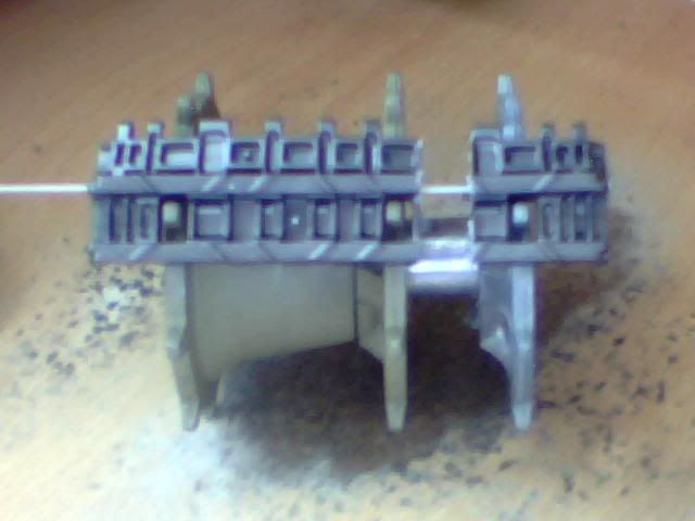
First the old arrangement which looked wierd and flimsy;
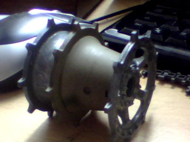
And now the new rugged arrangement which I think looks much more acceptable. In this configuration the central teeth will barely even be noticeable.
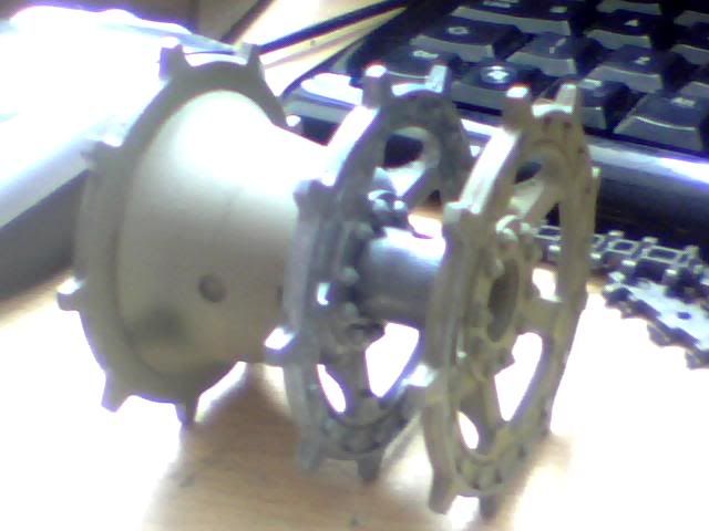
Here's a final image showing how perfectly suited these parts are to stacking.
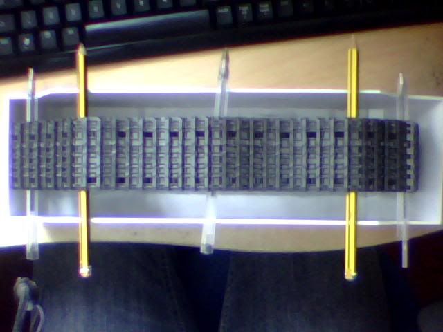
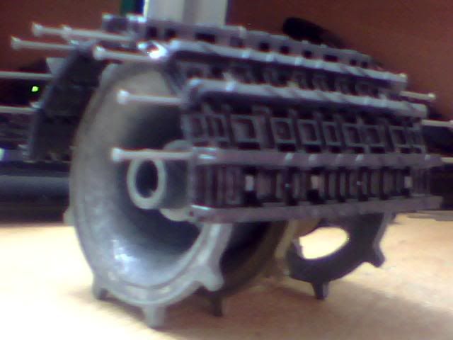
The drive wheel wasn't the only thing I changed as ultimately that's only an aesthetic improvement and my real concern is strength. To this end I decided to try and increase the number of contacts that the pins have as they pass through each link. I'm told that not all tracks have this issue but the sets I'm working with only have holes at either end of each piece rather than all the way through. That gives me 4 contacts for each link and I'd noticed that the pieces I'd made up yesterday (before these revisions) were holding a slight curve which didn't look good or bode well for strength. The following image shows how I've managed to get an extra point of contact into each link by moving the cut on every other piece to include an additional end hole. Now each pin has 5 contacts...
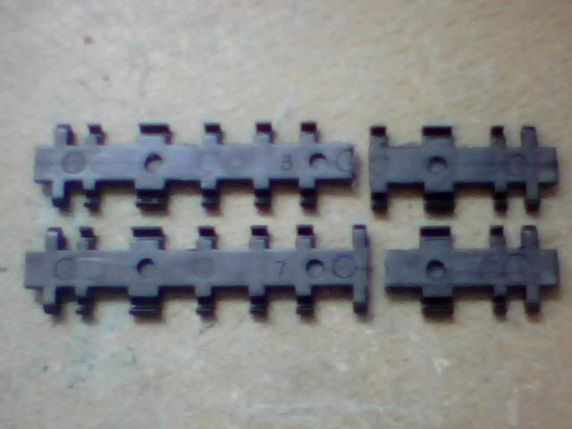
This next pic shows where the pins pass through holes and where it simply sits inside the track. It also shows how the cuts are staggered although you'll have to look closely. That's another improvement on yesterdays first prototype anyway and will increase strength in the same way staggered brickwork keeps a wall strong.
Here's the surface looking ok, the slight bow in the middle is a piece that I've cut at an angle so it's trying to bend outwards.
It's worth noting that I haven't used any kind of glue on these pieces today so the strength is all in the pins which are still only half the length they should be. That means I'm producing a prototype that will be significantly weaker than the final product if this is something I go ahead with. Consider it a worse case scenario... In the final design there will be full length pins to further protect from bending forces and some form of glue or heat applied to join the pieces of track to their newly introduced neighbours.
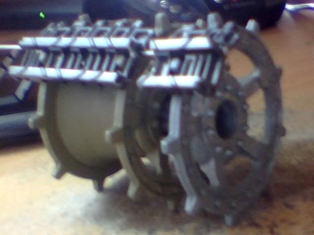
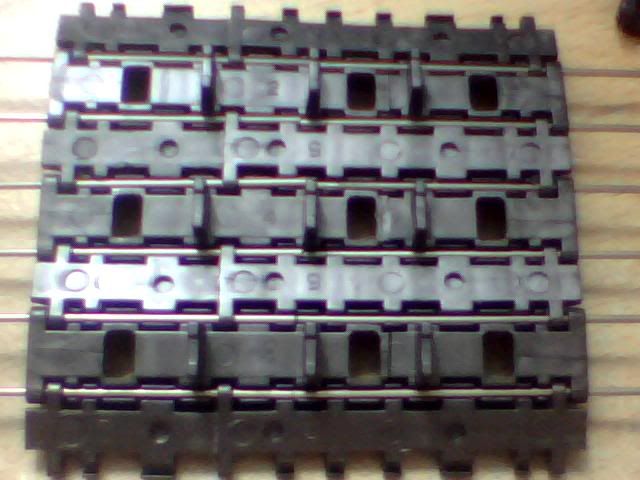
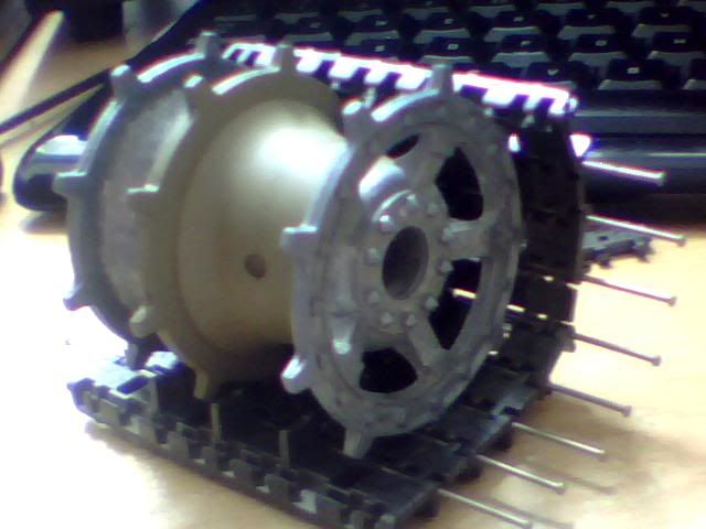
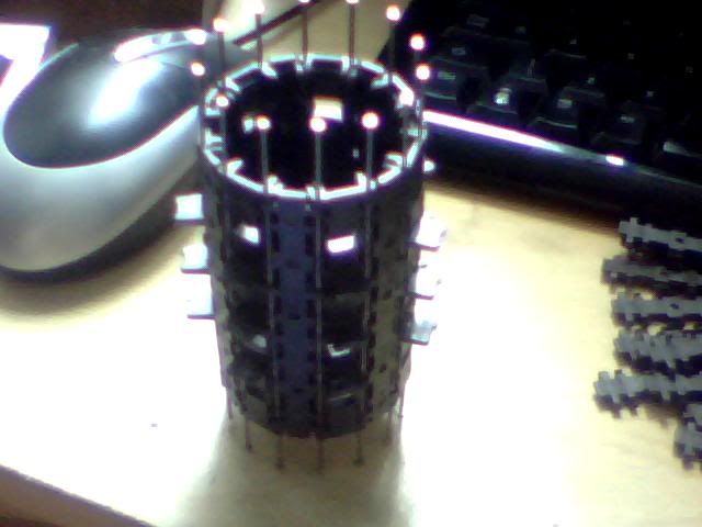
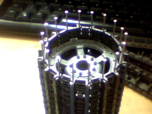
Here are some shots of 9 links and how they fit on the drive wheel. Again, the wheel is all loose fitted with no glue of other fastening to hold it together.
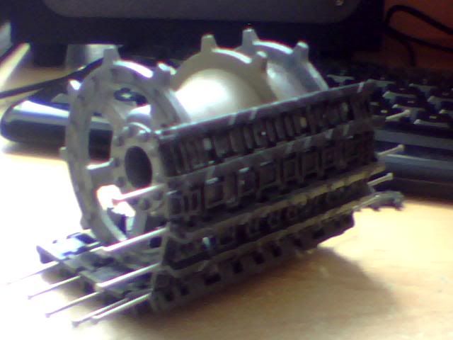
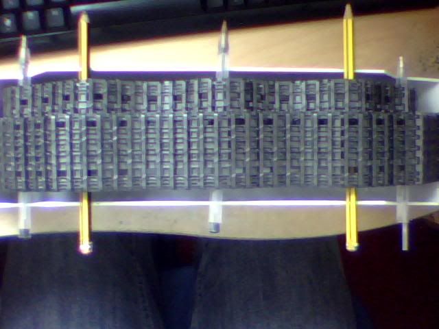
Finally a bunch of shots I took with it mock fitted inside the armour plating. Of course there will be much more detail added to that later but it gives a general idea of scale and size.
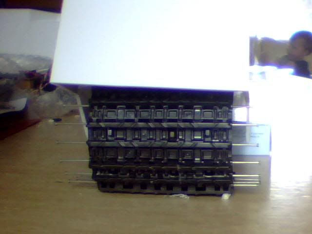
Noone will notice this but I have to say it anyway. For some reason I put that wheel in backwards as the final assembly will see it all reversed. The angle on top of the armour means everything will only go together one way! Here's a last shot of just the track for scale.
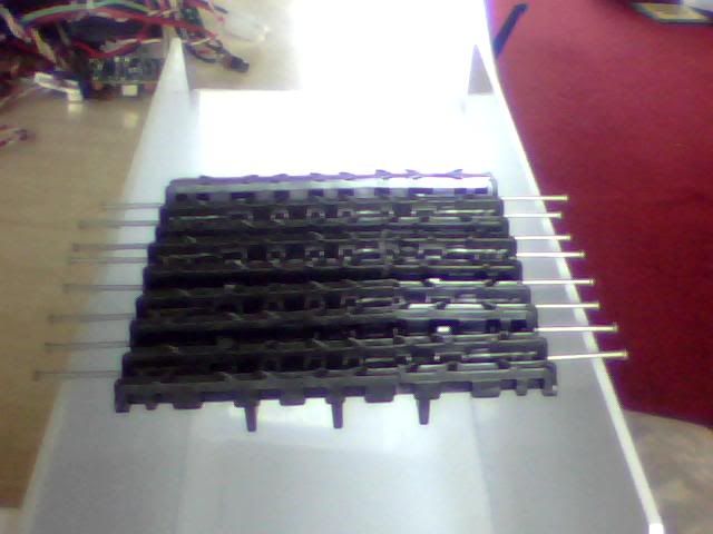
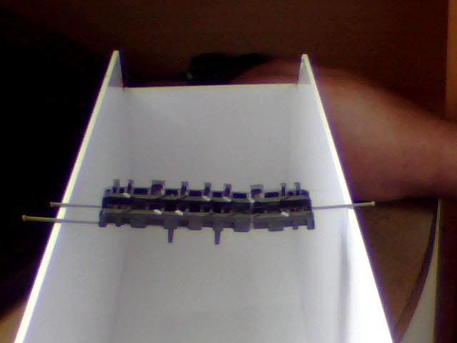
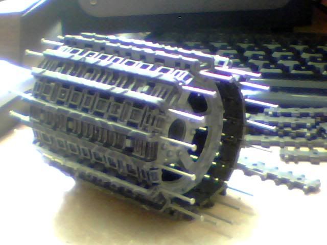
Here's a picture I took when I had 14 pieces made, just enough to wrap it around itself and see how strong it was coming out. In this very unnatural configuration it was easy to push the larger pieces outward (or inward in this setup) slightly but in the future all pressure will come from outside pushing in AND there will be glue as well so it doesn't worry me at this stage.
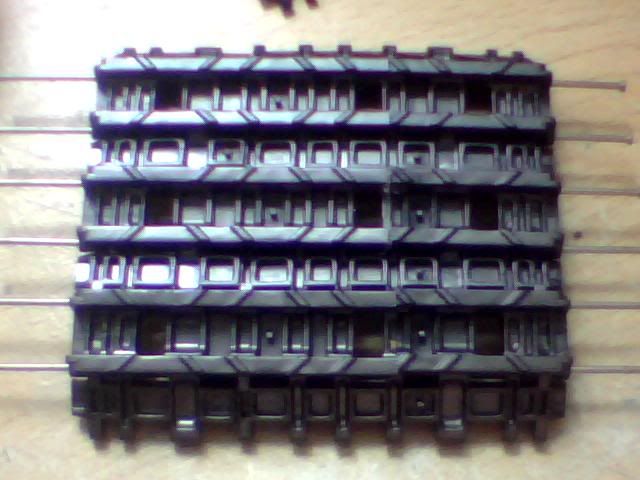
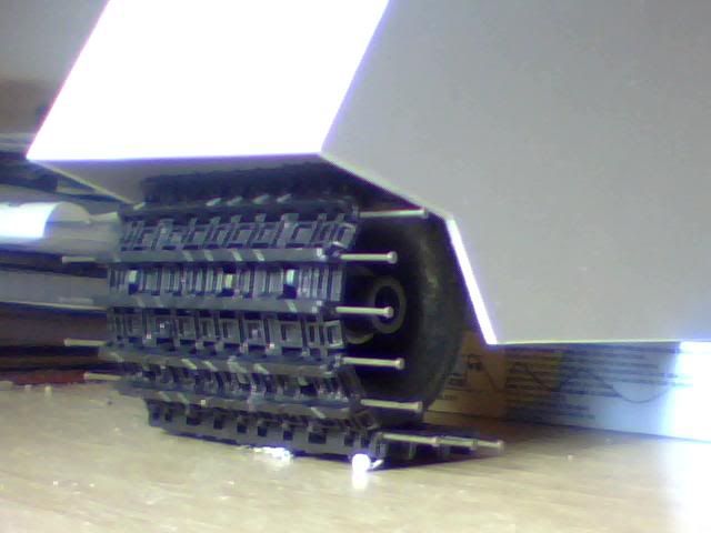
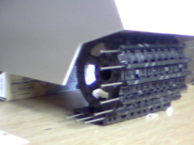
And finally, the last thing I've got round to doing so far. Again a very unnatural setup but I decided I'd make just enough pieces to wrap up the drive wheel so I could have a good look at it. I'm very pleased so far but here are some pics so you can judge too!
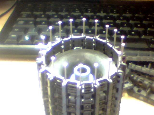
I had a play with this to see how happy I was with strength and rigidity and it's pretty good, I even gave it to my toddler for a while and it survived perfectly well after some kicking and rolling (thankfully no throwing!) around.
The next test for this configuration will be to make a small rig with 2 drive wheels and enough track to stretch between them. Ultimately, the drive wheels will provide plenty of strength to the track as it passes over and round them so the bigger issue is how this design behaves when it is either lying on the ground with no weight directly above it or hanging free at the top of the track between bogeys. I may do that today as I'm getting quite quick at this but we'll see! Still no sign of my grill yet which is a bit disappointing, I've got a package from the pacific ocean in less time than this one has been in the post... Still, the posties of the world don't work to my agenda I'm sure, or maybe there's some sort of conspiracy who knows!
For now I'll leave you with my next step which involves making a lot more links and setting up a simple 2-wheel system for some further testing. I also need some 1mm metal rod in order to replace the pin system I'm currently using as that does somewhat complicate matters. If anyone works somewhere they can borrow some from please let me know! Not sure where to go for it round here but will check the hardware stores when I'm out tomorrow or failing that I know a model shop that should sell all sizes of rod. Will be ruddy expensive though I think...
Feedback as always, does this look like a good plan or am I completely mad and will it fall apart the second I try to put power through the drive wheels or take it off road?
First brainwave I had was just dumb luck that I noticed something out of the corner of my eye whilst sat at this very computer and still in the process of waking up. My last update yesterday was how I thought of using a double wide drive wheel to engage the maximum amount of track possible but it would've needed some pretty major modifications to make it look sturdy.
This morning I realised that I'd missed a trick but now I've caught up with myself here's the deal... Each of these drive wheels split in half, hence my ability to extend one full wheel with the face of another one. As I sat down this morning this trio of parts was sat staring me in the face and next to it was the unused rear of the second drive wheel I nicked the front off. Turns out you can very easily stack the rear parts of these drive wheels and they slot together perfectly with next to no movement! It also provides exactly the same additional distance between the 2nd and 3rd row of holes! Here's what I mean...
First the old arrangement which looked wierd and flimsy;
And now the new rugged arrangement which I think looks much more acceptable. In this configuration the central teeth will barely even be noticeable.
Here's a final image showing how perfectly suited these parts are to stacking.
The drive wheel wasn't the only thing I changed as ultimately that's only an aesthetic improvement and my real concern is strength. To this end I decided to try and increase the number of contacts that the pins have as they pass through each link. I'm told that not all tracks have this issue but the sets I'm working with only have holes at either end of each piece rather than all the way through. That gives me 4 contacts for each link and I'd noticed that the pieces I'd made up yesterday (before these revisions) were holding a slight curve which didn't look good or bode well for strength. The following image shows how I've managed to get an extra point of contact into each link by moving the cut on every other piece to include an additional end hole. Now each pin has 5 contacts...
This next pic shows where the pins pass through holes and where it simply sits inside the track. It also shows how the cuts are staggered although you'll have to look closely. That's another improvement on yesterdays first prototype anyway and will increase strength in the same way staggered brickwork keeps a wall strong.
Here's the surface looking ok, the slight bow in the middle is a piece that I've cut at an angle so it's trying to bend outwards.
It's worth noting that I haven't used any kind of glue on these pieces today so the strength is all in the pins which are still only half the length they should be. That means I'm producing a prototype that will be significantly weaker than the final product if this is something I go ahead with. Consider it a worse case scenario... In the final design there will be full length pins to further protect from bending forces and some form of glue or heat applied to join the pieces of track to their newly introduced neighbours.
Here are some shots of 9 links and how they fit on the drive wheel. Again, the wheel is all loose fitted with no glue of other fastening to hold it together.
Finally a bunch of shots I took with it mock fitted inside the armour plating. Of course there will be much more detail added to that later but it gives a general idea of scale and size.
Noone will notice this but I have to say it anyway. For some reason I put that wheel in backwards as the final assembly will see it all reversed. The angle on top of the armour means everything will only go together one way! Here's a last shot of just the track for scale.
Here's a picture I took when I had 14 pieces made, just enough to wrap it around itself and see how strong it was coming out. In this very unnatural configuration it was easy to push the larger pieces outward (or inward in this setup) slightly but in the future all pressure will come from outside pushing in AND there will be glue as well so it doesn't worry me at this stage.
And finally, the last thing I've got round to doing so far. Again a very unnatural setup but I decided I'd make just enough pieces to wrap up the drive wheel so I could have a good look at it. I'm very pleased so far but here are some pics so you can judge too!
I had a play with this to see how happy I was with strength and rigidity and it's pretty good, I even gave it to my toddler for a while and it survived perfectly well after some kicking and rolling (thankfully no throwing!) around.
The next test for this configuration will be to make a small rig with 2 drive wheels and enough track to stretch between them. Ultimately, the drive wheels will provide plenty of strength to the track as it passes over and round them so the bigger issue is how this design behaves when it is either lying on the ground with no weight directly above it or hanging free at the top of the track between bogeys. I may do that today as I'm getting quite quick at this but we'll see! Still no sign of my grill yet which is a bit disappointing, I've got a package from the pacific ocean in less time than this one has been in the post... Still, the posties of the world don't work to my agenda I'm sure, or maybe there's some sort of conspiracy who knows!
For now I'll leave you with my next step which involves making a lot more links and setting up a simple 2-wheel system for some further testing. I also need some 1mm metal rod in order to replace the pin system I'm currently using as that does somewhat complicate matters. If anyone works somewhere they can borrow some from please let me know! Not sure where to go for it round here but will check the hardware stores when I'm out tomorrow or failing that I know a model shop that should sell all sizes of rod. Will be ruddy expensive though I think...
Feedback as always, does this look like a good plan or am I completely mad and will it fall apart the second I try to put power through the drive wheels or take it off road?
