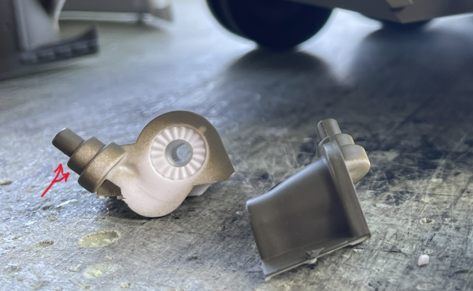
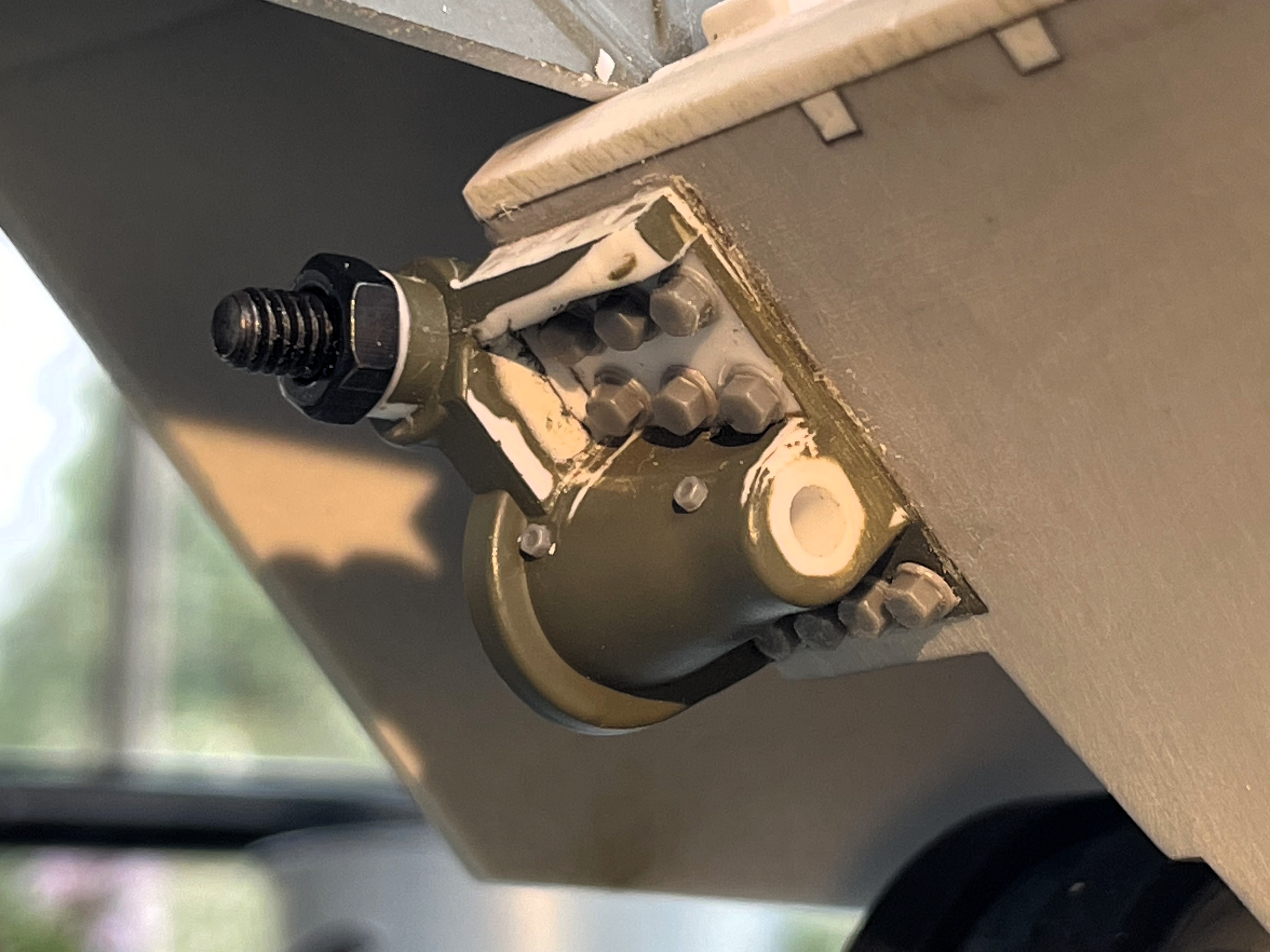
The Idler adjuster.
View of the real thing. We can see the large bolt heads, the large 6 attachment bolts in the middle, 2 oil points, the large bolt and nut on the right. There are also 4 attachment bolts at the bottom.
'

- 1/16 RC IDF Late Sho't Meteor Centurion with 105mm - build
- 12.JPG (1.68 MiB) Viewed 981 times
The TONGDE idler adjuster part is made of plastic. I would have liked to see it in metal but this is what we have. It's quite ugly but it can be easily improved, like the tip here of the main bolt and nut, shown as some blob. It can be replaced by a real metal bolt and nut.
- 1/16 RC IDF Late Sho't Meteor Centurion with 105mm - build
- 10a.png (438.43 KiB) Viewed 981 times
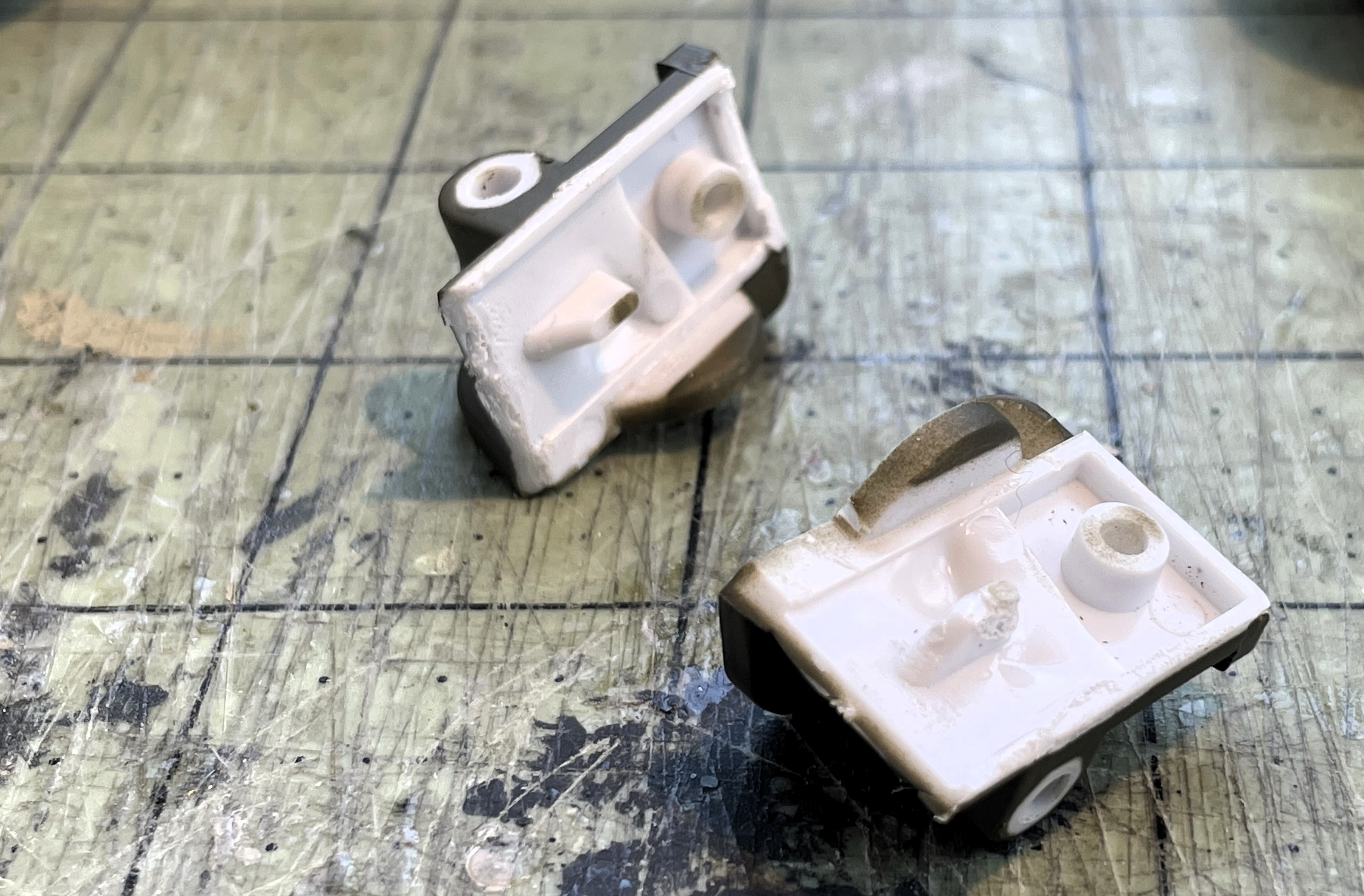
View underneath the adjusters, they seem weak for use as idler adjusters for metal suspension and tracks. I was able to pop out both of them from their sockets with a simple twist of a blade. They were holding by a couple of drops of glue.
- 1/16 RC IDF Late Sho't Meteor Centurion with 105mm - build
- 11.JPG (1.06 MiB) Viewed 981 times
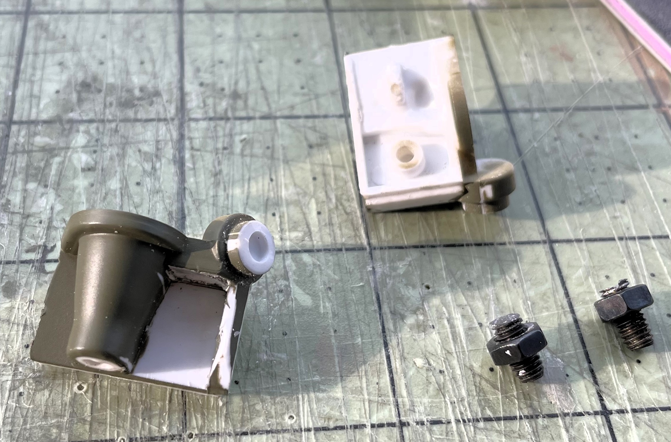
Cleaning up all the details, including the terrible 9 round bolt heads on the front, and the 4 on the top... But details can wait, my first concern is to install them solidly.
- 1/16 RC IDF Late Sho't Meteor Centurion with 105mm - build
- 13.JPG (709.52 KiB) Viewed 981 times
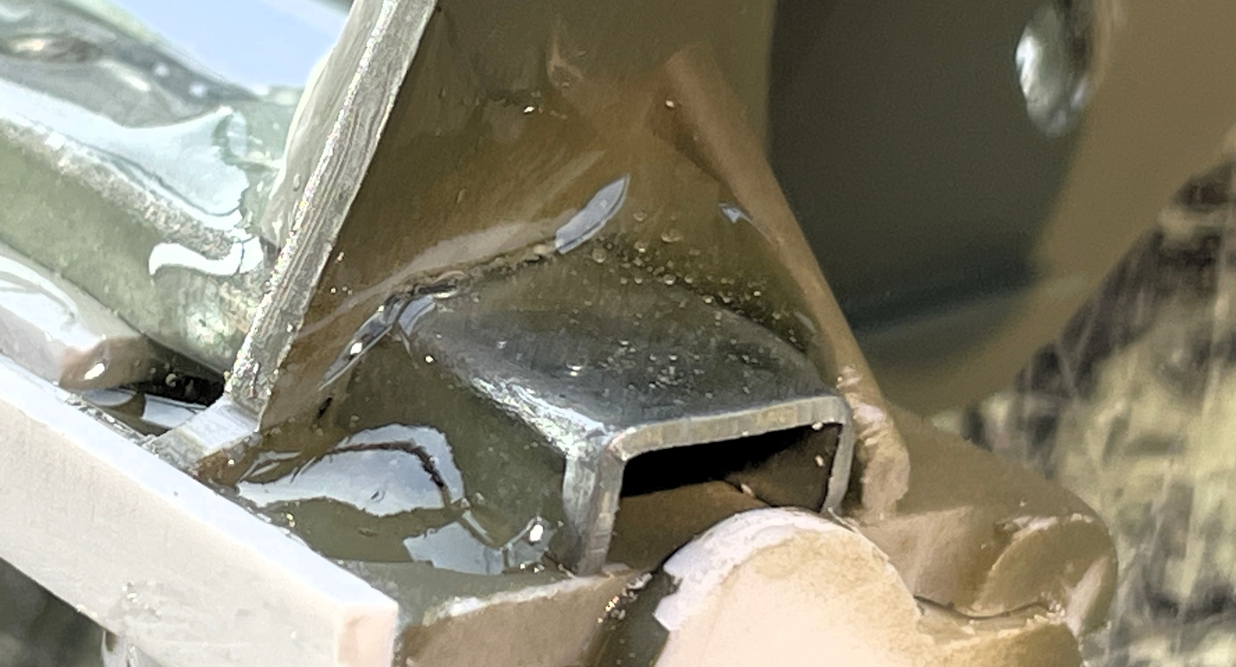
The idler adjusters are glued back on the hull, soaking in Epoxy glue underneath, but making sure to remove any overflow on the sides, and not getting near the hole for the Idlers shaft.
It's already better, at least it might break but it won't fall off...
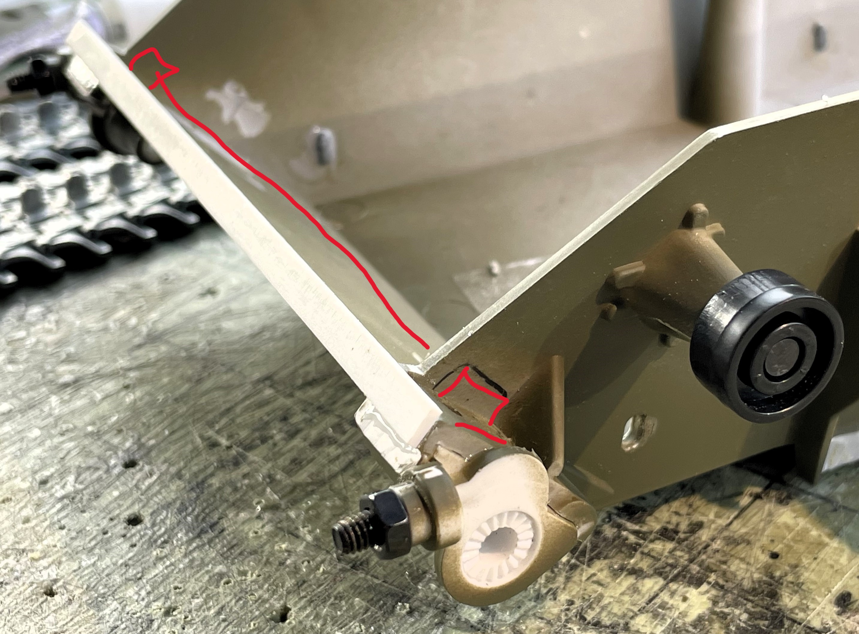
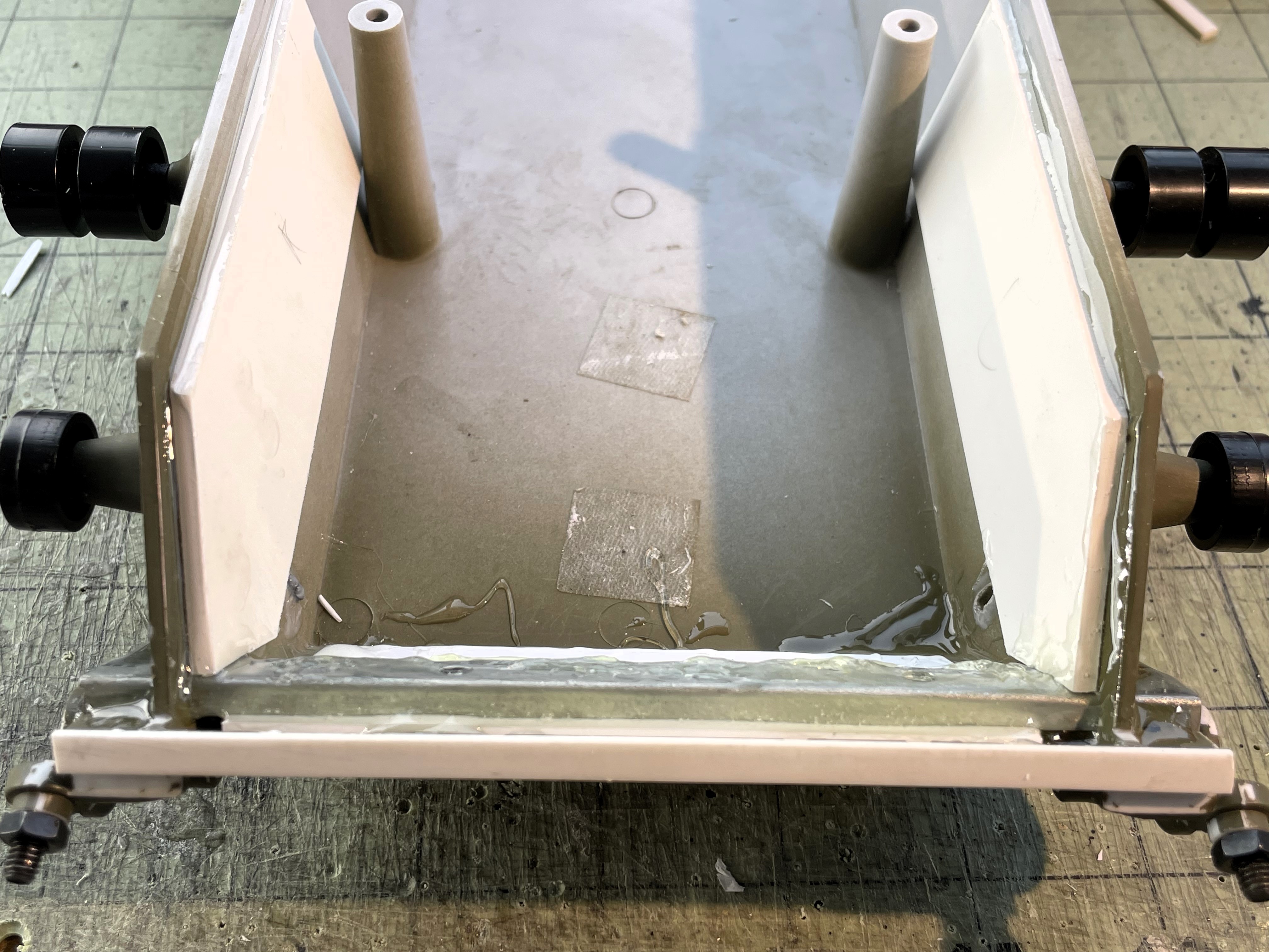
But i want to reinforce it with some metal plate somewhere to prevent the plastic of the front armor plate to bend at the corners with the adjusters, or distord. I have analysed a few options. Based on the material i have available, i determined that my best option is to slide a transversal metal beam end to end at the base of the armored plates behind the adjusters, proposed location in red. Its simple and it will not show.
- 1/16 RC IDF Late Sho't Meteor Centurion with 105mm - build
- 14.JPG (935.49 KiB) Viewed 981 times
I had this metal beam on inventory, a metal U beam. It's probably coming from some unused hardware for a furniture drawer purchased years ago. I keep everything that i think could be of use.
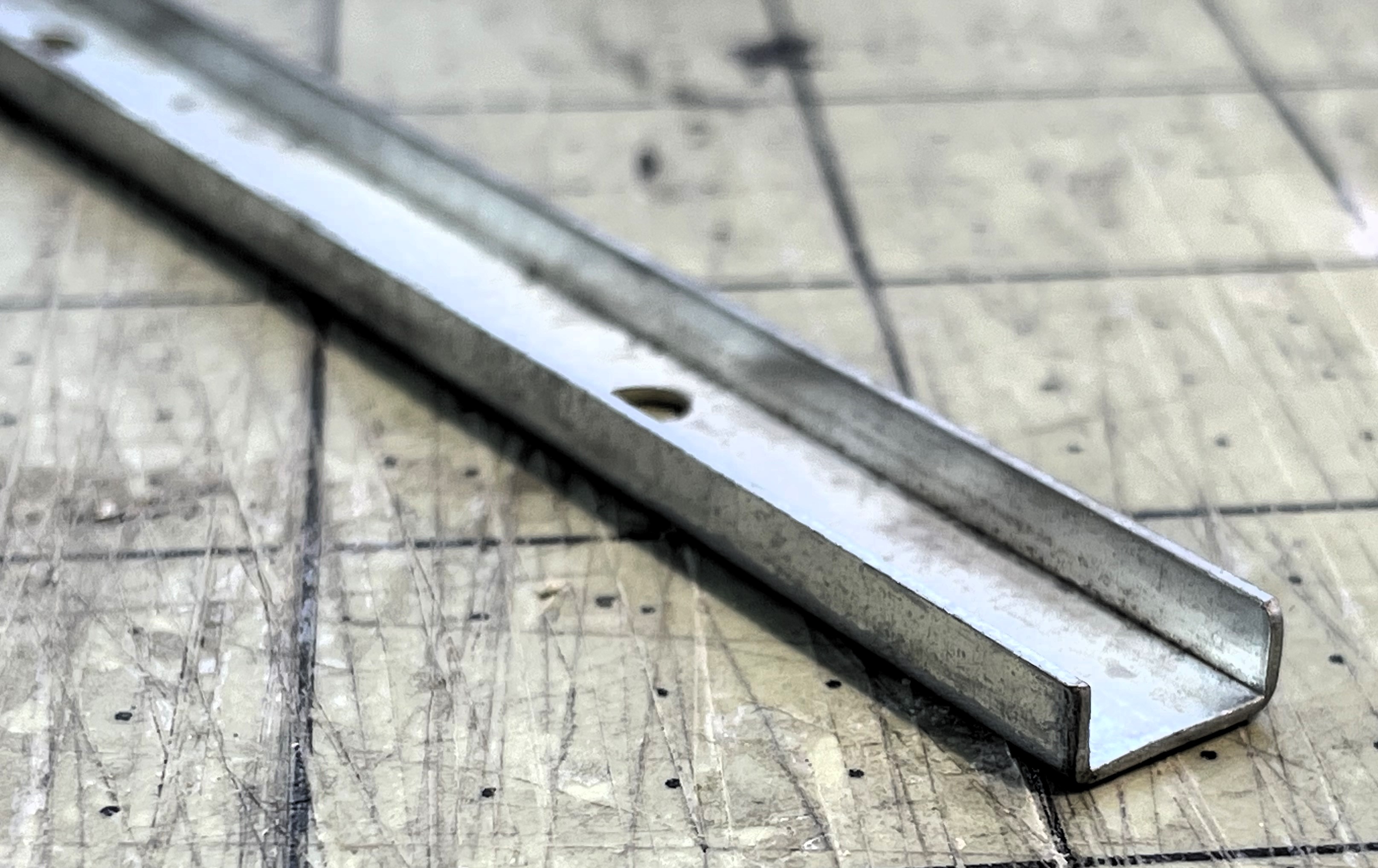
- 1/16 RC IDF Late Sho't Meteor Centurion with 105mm - build
- 14a.JPG (916.52 KiB) Viewed 981 times
After the tight fiting holes are made on the wall section just behind the plastic plate for the adjuster, i installed the beam, gave it a 2mm spacer to fill the gap with the rear of the frontal armor, then i soaked the whole thing in epoxy. Then added two long 4mm thick plasticard plates on both side walls as additional reinforcement, again with epoxy. The idler adjusters might still break but they won't bring the whole front of the tank with them...
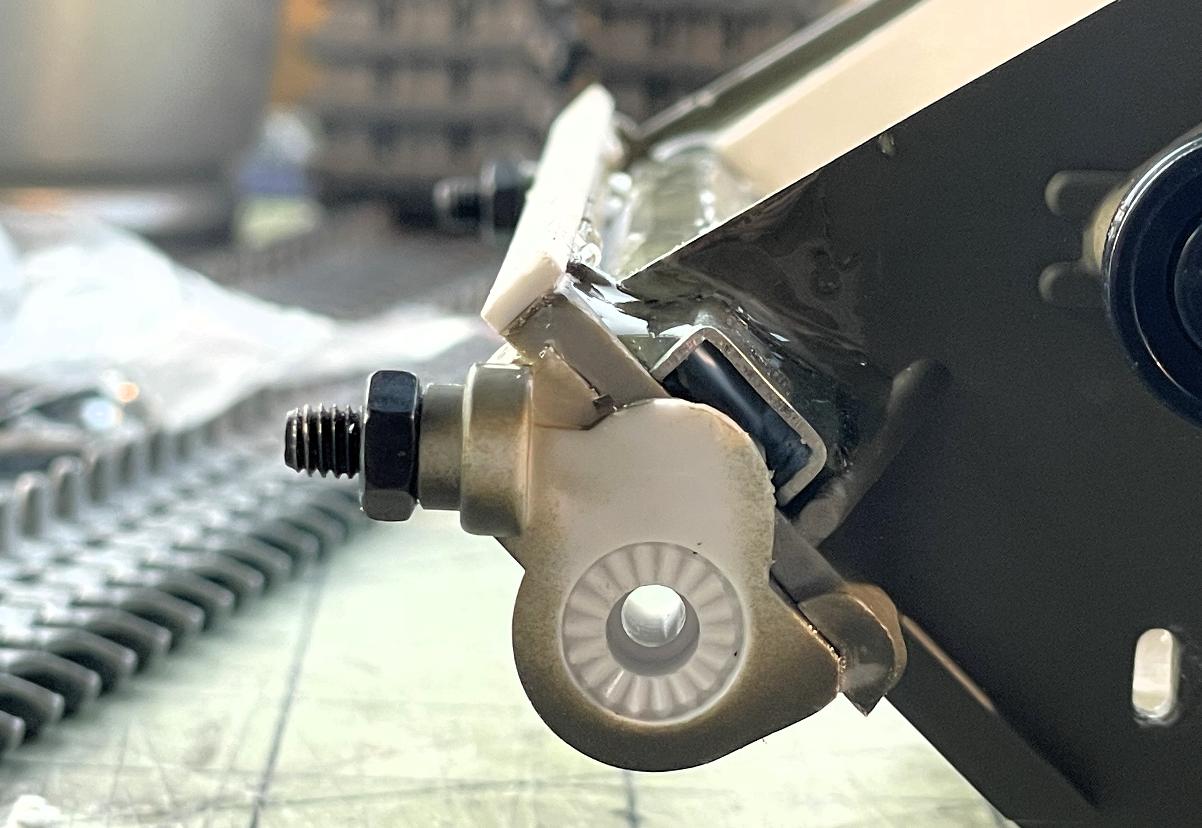
If the plastic adjusters still eventually break, then a more drastic option of replacing them with Tamiya or other brands of 1/16 Centurion idler adjusters is an option, but it would require the idler shaft and wheels or other custom parts to integrate with the TONGDE hull. Could be costly.
- 1/16 RC IDF Late Sho't Meteor Centurion with 105mm - build
- 15.JPG (1.83 MiB) Viewed 981 times
- 1/16 RC IDF Late Sho't Meteor Centurion with 105mm - build
- 16.JPG (853.05 KiB) Viewed 981 times
- 1/16 RC IDF Late Sho't Meteor Centurion with 105mm - build
- 17.JPG (1.46 MiB) Viewed 981 times
Then the details on the front are added. At one point, I wanted to use real metal bolts but felt drilling holes would weaken the part, not make it stronger.
- 1/16 RC IDF Late Sho't Meteor Centurion with 105mm - build
- 18.JPG (1.09 MiB) Viewed 981 times
This is it for the idler adjusters.

