Page 4 of 8
Re: Herr Doc's Various Questions
Posted: Wed Jan 29, 2025 10:49 pm
by Herr Dr. Professor
Jofaur86: thank you for another useful diagram. I may be one of the few here on RCTW with much more experience updating Taigen/Torro tanks to V3 than upgrading Heng Long tanks. Despite the fact that Taigen/Torro is now lagging behind Heng Long and TongDe on matters of control, upgrading Taigen/Torro MFUs from earlier versions to V3 (with the little sound "modules") is an easy one-to-one swap of connectors.
Re: Herr Doc's Various Questions
Posted: Wed Jan 29, 2025 10:51 pm
by Jofaur86
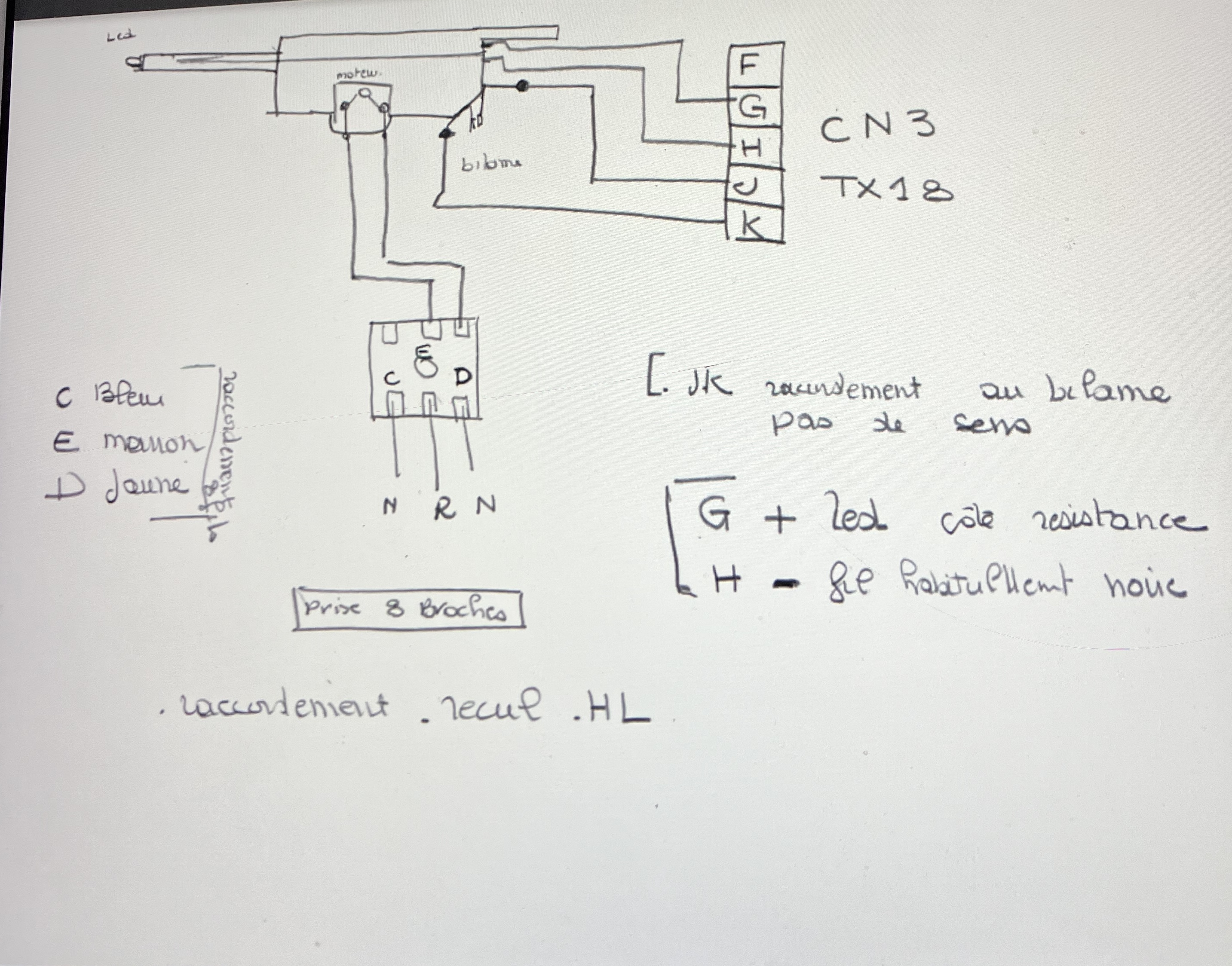
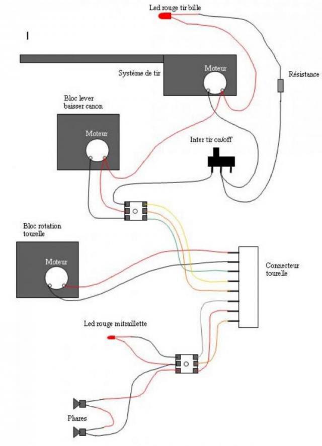
another, very old BB shooting system diagram origin HL

- IMG_4320.jpeg (1.83 MiB) Viewed 3252 times

- IMG_4321.jpeg (44.55 KiB) Viewed 3252 times
Re: Herr Doc's Various Questions
Posted: Wed Jan 29, 2025 11:34 pm
by tankme
Herr Dr. Professor wrote: ↑Wed Jan 29, 2025 10:40 pm
Thank you,
tankme: that is most helpful. I thought DuPont connector was the same as JST on servos. I have a zillion or so such connectors, as all the V3 electronics for Taigen tanks I updated came with multiple connectors ready to go.
A note for others: when I changed over the motors and power wires to bullet connectors, I first stripped and neatly tinned the wires. It may well be that bullet connectors crimp more readily and hold better if a braided wire is not tinned. Regardless, I have the connectors ready to stay put against any strain they will encounter.
Me being me, I tend to tin the wire, insert it into the connector, solder it to the connector, and then use my crimping tool the just crimp the ears of the connector down. I've had too many crimped connections fail so now they ALL get soldered.

Re: Herr Doc's Various Questions
Posted: Thu Jan 30, 2025 11:20 am
by Jofaur86

Hello, it is certain that the "tank" solution (welds) is the best and safest contact level, the ears of these terminals are intended to be crimped onto the insulation
Re: Herr Doc's Various Questions
Posted: Tue Feb 04, 2025 8:09 pm
by Herr Dr. Professor
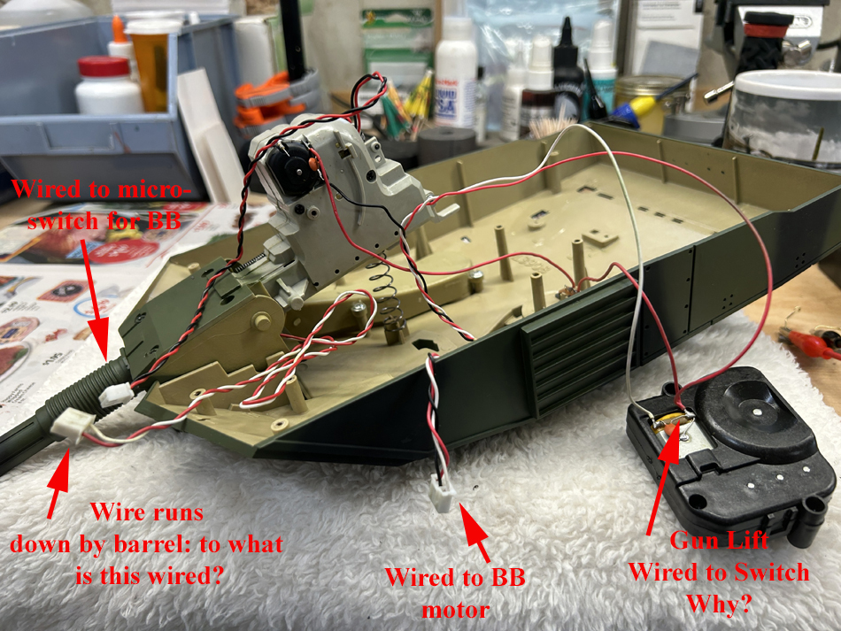
To get started changing out to JST and Dupont connections, I wanted to test all the functions (except the BB firing, which I can do without if it doesn't readily work). I have two matters that are perplexing me. 1) what is the wire that runs down apparently alongside the barrel to a JST connector. It seems to be neither the BB motor nor the micro-switch. (This tank is from 2013, no recoil nor flash.)
Why is the gun elevation motor connected through the "safety" switch mounted in the coupola? The turret elevation doesn't work as wired, but if I go directly to the turret motor, it works fine.

- Turret Wiring.jpg (590.45 KiB) Viewed 3072 times
Re: Herr Doc's Various Questions
Posted: Tue Feb 04, 2025 8:27 pm
by Jofaur86
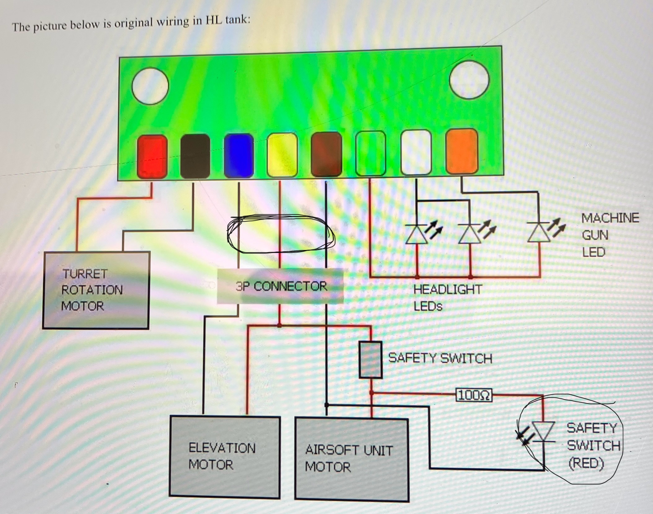
Hello, Personally, I would say that it is the wire from the BB firing motor which passes through the safety interlock and which is transplanted onto the rotation motor, because it is common, see my diagram attached above? The wire which goes down the length of the barrel ? Wouldn't the control LED be fixed in principle on the mantel?
Re: Herr Doc's Various Questions
Posted: Tue Feb 04, 2025 8:41 pm
by Jofaur86
Like this, surrounded in black

- IMG_0788.jpeg (774.44 KiB) Viewed 3067 times
Re: Herr Doc's Various Questions
Posted: Wed Feb 05, 2025 2:19 am
by Herr Dr. Professor
Merci à Jofaur pour son aide patiente. I saw the three pin connector in your diagram on the previous page and as you even more clearly identify it just immediately above. In fact, I printed out enlargements of all the helpful diagrams I have from you and others. What is puzzling me is that the gun elevation motor seems not to work unless I connect directly to it. Your diagrams clearly show that the safety switch(es) should disable only the airsoft unit motor. Yet something is affecting the elevation motor too. I will keep testing to diagnose the location of the problem. Perhaps the wiring problem may be between the two-pin JST connector for the elevation motor that ran from the tank's original TK5.3 and the elevation motor itself, as the elevation did not work when connected to the TK5.3. I am learning all along and acquiring rather an array of connectors and testing aids, such as a DC Variable Bench Power Supply, ever so handy.
Re: Herr Doc's Various Questions
Posted: Wed Feb 05, 2025 1:18 pm
by Jofaur86
Mr. Professor, if you use 7.0 card, you need to modify the wiring of the "elevation" motor in two wires on the direct CN 3 connector, if I followed correctly? actually the switch only cuts the BB firing motor (safety for children) so you can join the 2 wires and remove this switch!!!
Re: Herr Doc's Various Questions
Posted: Wed Feb 05, 2025 4:10 pm
by Herr Dr. Professor
Yes, Jofaur86: you have described exactly what I was hoping to do. Thank you!