Playing lots of video games and collecting dust. I don't even know where 2015 went.ALPHA wrote:ZUUL!!!! Where you been buddySovereignZuul wrote:Looking good TFTM, really love that starter crank.
ALPHA
Building a Mid-Production Normandy Tiger 1
-
SovereignZuul

- Corporal
- Posts: 456
- Joined: Sat Aug 25, 2012 11:50 pm
- Location: Connecticut, USA
Re: Building a Mid-Production Normandy Tiger 1
My Build Thread: http://www.rctankwarfare.co.uk/forums/v ... 22&t=10204
-
doc larsson
- Staff Sergeant
- Posts: 829
- Joined: Sat Sep 29, 2012 5:05 pm
Re: Building a Mid-Production Normandy Tiger 1
is it a camshaft ? for a crankshaft on a maybach engine, like any other vehicle wouldn't look like that ? amazed that you would carry such a vital spare on the engine on the exterior 
-
tanks_for_the_memory
- Sergeant
- Posts: 501
- Joined: Tue Jan 04, 2011 4:50 pm
- Location: London
Re: Building a Mid-Production Normandy Tiger 1
Doc,
Whether it be a crank or a cam shaft it has to be remembered that this was for turning over the tank's engine when it was cold - not a spare for the actual engine to work...
Anyway, on with the show.
The jack block
The jack block was a common feature on German WWII tanks. On the Tiger 1 it was carried on the hull roof to the left of the radio operator's hatch. I have already discussed above how its position was changed slightly once the centrally mounted headlight was fitted.
The block itself was made of wood, held together with strengthening ribs which were pinned or nailed in place. A carrying handle was also fitted to one edge. When stowed the block fitted into four brackets attached to the hull roof and there was a retaining bar which hinged from the rear and fitted over the block to clamp it in place at the front.
The Heng Long Tiger comes with a very crude approximation of the block. The Tamiya part is better, but there is no handle and the moulded retaining bar and clamp can only go so far to match the detail of the real thing.
Once again I used the Voyager photo-etch set. Like all the other clamps in the set this one can be made to work so that theoretically you would be able to remove the block to assist with painting. However, I had serious doubts about its survivability on an RC tank - so I opted to make the whole assembly removable.
Some people have used a piece of real wood (either balsa or hardwood) for the block itself. This has the advantage of giving the block a realistic wood appearance from the start, but in this scale I still think you can achieve this with a little texture and a good paint job. Besides, a photo I have seen in AFV Modeller magazine from a collection of parts recovered from destroyed Tigers in Normandy suggests that the block itself would have been painted black in any event.
So I chose to use the original HL part which I removed from the hull some time ago with a razor saw. I then sanded this down to remove what detail there was and used rougher sandpaper to give it a wood grain effect. The lines between the individual blocks were then scribed in with the upside-down tip of a craft knife.
I then started working with the Voyager photo etch parts. The strengthening ribs have a lovely riveted texture. The handle was a little more fiddly but again adds a realistic touch.
By far the most fiddly bit is the front clamp for the retaining bar, which involves inserting a thin piece of wire through four tiny holes which have to be lined up correctly in order for it to work. Quite apart from the difficulty of seeing what you are doing (impossible for me without a magnifying lamp) the only way I found to achieve this was to hold the parts in place with some double-sided tape. Because I did not intend to leave mine workable I then glued everything in place.
Whether it be a crank or a cam shaft it has to be remembered that this was for turning over the tank's engine when it was cold - not a spare for the actual engine to work...
Anyway, on with the show.
- The jack block was another challenging piece using the Voyager set - but I think it's worth it!.jpg (36.56 KiB) Viewed 13996 times
The jack block was a common feature on German WWII tanks. On the Tiger 1 it was carried on the hull roof to the left of the radio operator's hatch. I have already discussed above how its position was changed slightly once the centrally mounted headlight was fitted.
The block itself was made of wood, held together with strengthening ribs which were pinned or nailed in place. A carrying handle was also fitted to one edge. When stowed the block fitted into four brackets attached to the hull roof and there was a retaining bar which hinged from the rear and fitted over the block to clamp it in place at the front.
The Heng Long Tiger comes with a very crude approximation of the block. The Tamiya part is better, but there is no handle and the moulded retaining bar and clamp can only go so far to match the detail of the real thing.
Once again I used the Voyager photo-etch set. Like all the other clamps in the set this one can be made to work so that theoretically you would be able to remove the block to assist with painting. However, I had serious doubts about its survivability on an RC tank - so I opted to make the whole assembly removable.
Some people have used a piece of real wood (either balsa or hardwood) for the block itself. This has the advantage of giving the block a realistic wood appearance from the start, but in this scale I still think you can achieve this with a little texture and a good paint job. Besides, a photo I have seen in AFV Modeller magazine from a collection of parts recovered from destroyed Tigers in Normandy suggests that the block itself would have been painted black in any event.
So I chose to use the original HL part which I removed from the hull some time ago with a razor saw. I then sanded this down to remove what detail there was and used rougher sandpaper to give it a wood grain effect. The lines between the individual blocks were then scribed in with the upside-down tip of a craft knife.
- This is the original Heng Long jack block which I removed from the hull with a razor saw and then sanded down.jpg (33.38 KiB) Viewed 13996 times
- Lines were then drawn on with a pencil....jpg (34.99 KiB) Viewed 13996 times
- ...before the edge of a knife blade was used to gouge out the joint lines.jpg (35.85 KiB) Viewed 13996 times
- A comparison with the Tamiya jack block before adding the retaining bar and corner brackets.jpg (35.99 KiB) Viewed 13996 times
- Using double-sided tape to hold everything in place was the only way I found to insert the wire through the clamp.jpg (31.74 KiB) Viewed 13996 times
- The retaining bar and corner brackets now in place.jpg (34.79 KiB) Viewed 13996 times
- The finished jack block temporarily in place - it should look much better with a coat of paint.jpg (45.87 KiB) Viewed 13996 times
Last edited by tanks_for_the_memory on Thu Jan 14, 2016 10:22 pm, edited 1 time in total.
My Mid-Production Normandy Tiger 1 build thread: http://www.rctankwarfare.co.uk/forums/v ... =22&t=8350
-
PainlessWolf
- Colonel
- Posts: 7970
- Joined: Sun Feb 26, 2012 9:09 pm
- Location: Southern Colorado Rocky Mountains
Re: Building a Mid-Production Normandy Tiger 1
TFTM,
Are you sure that you are not Bob Steinbrunn in here using a disguise? Your work is magnificent as always! Black for the jack blocks on Normandy Tigers. Noted.
regards,
Painless
Are you sure that you are not Bob Steinbrunn in here using a disguise? Your work is magnificent as always! Black for the jack blocks on Normandy Tigers. Noted.
regards,
Painless
...Money!? What's that!?...
-
tanks_for_the_memory
- Sergeant
- Posts: 501
- Joined: Tue Jan 04, 2011 4:50 pm
- Location: London
Re: Building a Mid-Production Normandy Tiger 1
Thanks Painless - no idea who Bob Steinbrunn is/was but he sounds like someone I should aspire to be!
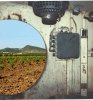
Here's the picture I was talking about, taken from an article in issue 29 of AFV Modeller Magazine entitled 'Relics of a Death Ride'.
It's basically photographs of a collection of Tiger (and other) relics put together by a local Frenchman following the fierce battle that took place in the early afternoon of Tuesday 8 August 1944, along the N158 Caen-Falaise road in the vicinity of Cintheaux, Gaumesnil and Saint Aignan de Cramesnil. In particular there are pieces from two of the five Tiger 1’s belonging to schwere SS-Panzerabteilung 101 that were destroyed that day - the command Tiger “007” of SS-Hauptsturmführer Michael Wittmann and the mid-production Tiger “314”.
So even if you're not actually looking at a bit of Wittman's tank, you're almost certainly looking at one under his command.
Anyway, if you think about it painting the block (or staining it) makes a lot more sense than leaving it in bare wood - as any of us who have a shed will know!
- Tiger jack block recovered from Normandy with black paint - from AFV Modeller issue 29.jpg (18.19 KiB) Viewed 14629 times
It's basically photographs of a collection of Tiger (and other) relics put together by a local Frenchman following the fierce battle that took place in the early afternoon of Tuesday 8 August 1944, along the N158 Caen-Falaise road in the vicinity of Cintheaux, Gaumesnil and Saint Aignan de Cramesnil. In particular there are pieces from two of the five Tiger 1’s belonging to schwere SS-Panzerabteilung 101 that were destroyed that day - the command Tiger “007” of SS-Hauptsturmführer Michael Wittmann and the mid-production Tiger “314”.
So even if you're not actually looking at a bit of Wittman's tank, you're almost certainly looking at one under his command.
Anyway, if you think about it painting the block (or staining it) makes a lot more sense than leaving it in bare wood - as any of us who have a shed will know!
My Mid-Production Normandy Tiger 1 build thread: http://www.rctankwarfare.co.uk/forums/v ... =22&t=8350
-
tanks_for_the_memory
- Sergeant
- Posts: 501
- Joined: Tue Jan 04, 2011 4:50 pm
- Location: London
Re: Building a Mid-Production Normandy Tiger 1
Headlight base plates
This was a simple fix.
The original Tiger 1 headlights, which were mounted at the top front corners of the hull, were eventually both deleted and replaced with the central mounted light on the front plate in October 1943. However the original base plates, complete with screws, continued to be fitted in the original places until early 1944 - so they should still be there on mine.
I had sanded away the original Heng Long mounts years ago (I can't even remember what they looked like) so I had to make mine from scratch.
The dimensions are shown in David Byrden's helpful diagram below, but I simply used a spare Tamiya headlight mount and cut plastic card to size. I then used Masterclub bolts to complete them.
- The primed hatch and headlight mounting plate on the starboard side.jpg (34.54 KiB) Viewed 14590 times
The original Tiger 1 headlights, which were mounted at the top front corners of the hull, were eventually both deleted and replaced with the central mounted light on the front plate in October 1943. However the original base plates, complete with screws, continued to be fitted in the original places until early 1944 - so they should still be there on mine.
I had sanded away the original Heng Long mounts years ago (I can't even remember what they looked like) so I had to make mine from scratch.
The dimensions are shown in David Byrden's helpful diagram below, but I simply used a spare Tamiya headlight mount and cut plastic card to size. I then used Masterclub bolts to complete them.
- Headlight base plate dimensions courtsey of David Byrden.gif (4.47 KiB) Viewed 14590 times
- The Tamiys headlight bracket was used as a template.jpg (36.62 KiB) Viewed 14590 times
- Hexagon nuts from Masterclub MC435057 were just right size.jpg (36.19 KiB) Viewed 14590 times
- After drilling holes the Masterclub were glued in place and left to set before trimming.jpg (33.81 KiB) Viewed 14590 times
- One cover plate installed on the port side.jpg (33.99 KiB) Viewed 14590 times
My Mid-Production Normandy Tiger 1 build thread: http://www.rctankwarfare.co.uk/forums/v ... =22&t=8350
-
tanks_for_the_memory
- Sergeant
- Posts: 501
- Joined: Tue Jan 04, 2011 4:50 pm
- Location: London
Re: Building a Mid-Production Normandy Tiger 1
Fun with tools
Having started down the road of using Voyager photo-etch for the tool clamps I now had to tackle to rather busy arrangement of tools on the front hull roof.
As I have said before the layout differs depending on which phase of the Tiger's development you are representing. I was able to refer to the drawings in both Jentz & Doyle's Germany's Tiger Tanks and the excellent Modeler's Guide to the Tiger Tank (see my list of books above) so I'm pretty confident my choice is correct.
Of course accurately placing the tools on a 1/16 scale tank is another matter. I found that the best way to get it right was to use the hatch openings, jack block and armoured fan cover as a guide. By the way, on my model I used a restin casting for the latter which has a much better rounded profile than the Taigen metal part. I can't remember where I got it though...
A long time ago I had installed the C-hook and mounts using Taigen metal parts. However, when I started looking at tool placement I realised that it was a long way out of alignment. You can see some of the old holes filled in.
Since I had to move it I decided that I might as well use the Voyager mounts as well. In fact these are simply the metal bars which hold the C-hook in place. These were held in pace with dress making pins. For the hook itself I retained the Taigen one and for the mounting posts I used metal and plastic rod which was glued into holes drilled into the hull roof.
The butterfly nuts were the trusty Schumo ones - not cheap but beautifully cast and strong. As a result I could keep the mount functional and the C-hook can be removed for painting. I have done exactly the same for the mount on the rear of the hull.
It is important to get the C-hook in the right place because if you don't then it will be impossible to get the tools where they should be. Trust me - I found out the hard way!
For the tools - axe, sledge hammer and shovel - I had the Tamiya parts, which I planned to use with Voyager photo-etch clamps after the moulded equivalents are sanded away. However, I soon realized that the shovel had to be completely replaced if I wanted to use the lovely Voyager blade. I used a cocktail stick for the handle.
For now I have added all the tool mounts but not the actual clamps. I am going to leave these until almost everything else is finished in order to reduce the risk of accidental damage.
Having started down the road of using Voyager photo-etch for the tool clamps I now had to tackle to rather busy arrangement of tools on the front hull roof.
As I have said before the layout differs depending on which phase of the Tiger's development you are representing. I was able to refer to the drawings in both Jentz & Doyle's Germany's Tiger Tanks and the excellent Modeler's Guide to the Tiger Tank (see my list of books above) so I'm pretty confident my choice is correct.
Of course accurately placing the tools on a 1/16 scale tank is another matter. I found that the best way to get it right was to use the hatch openings, jack block and armoured fan cover as a guide. By the way, on my model I used a restin casting for the latter which has a much better rounded profile than the Taigen metal part. I can't remember where I got it though...
A long time ago I had installed the C-hook and mounts using Taigen metal parts. However, when I started looking at tool placement I realised that it was a long way out of alignment. You can see some of the old holes filled in.
Since I had to move it I decided that I might as well use the Voyager mounts as well. In fact these are simply the metal bars which hold the C-hook in place. These were held in pace with dress making pins. For the hook itself I retained the Taigen one and for the mounting posts I used metal and plastic rod which was glued into holes drilled into the hull roof.
The butterfly nuts were the trusty Schumo ones - not cheap but beautifully cast and strong. As a result I could keep the mount functional and the C-hook can be removed for painting. I have done exactly the same for the mount on the rear of the hull.
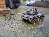
- The new C-hook mounts look more refined than the the metal cast Taigen versions.jpg (35.59 KiB) Viewed 14536 times
- Once again the Schumo butterfly nuts are the best option.jpg (34.37 KiB) Viewed 14536 times
- A view from above. Putting the armoured fan cover and C-hook in first gives you a better idea of where to place everything.jpg (36.29 KiB) Viewed 14536 times
- The Tamiya tools were stripped of their moulded fasteners except for the spade which I replaced altogether.jpg (38.27 KiB) Viewed 14536 times
- Another view of the tools.jpg (38.08 KiB) Viewed 14511 times
- The shovel holder is one of the trickier pieces from the Voyager set.jpg (33.15 KiB) Viewed 14536 times
- Front tool stowage all in place with only the actual clamps still to be added....jpg (42.41 KiB) Viewed 14536 times
- With all of the tools in place the upper deck starts to look rather crowded.jpg (37.02 KiB) Viewed 14536 times
Last edited by tanks_for_the_memory on Mon Feb 08, 2016 8:00 am, edited 2 times in total.
My Mid-Production Normandy Tiger 1 build thread: http://www.rctankwarfare.co.uk/forums/v ... =22&t=8350
-
DavidByrden
- Corporal
- Posts: 300
- Joined: Wed Sep 08, 2010 6:13 pm
- Contact:
Re: Building a Mid-Production Normandy Tiger 1
After studying many Tiger photos, I have come to believe that with something non-critical - like a tool - the factory workers would not bother to locate it closer than an inch to the correct position..
David
David
Re: Building a Mid-Production Normandy Tiger 1
I feel your pain with the shovel holder! Amazing work as always.
-
tanks_for_the_memory
- Sergeant
- Posts: 501
- Joined: Tue Jan 04, 2011 4:50 pm
- Location: London
Re: Building a Mid-Production Normandy Tiger 1
Zimmerit - the final frontier
It's been a long time coming (and even more since I decided to ditch the 'stick-on' version) - but the last coat of zimmerit has finally been applied...
There has been a slight controversy about whether Tiger 1's had zimmerit applied on the sloping surface between the lower hull front and the glacis plate - some modellers have chosen to put it on, others to leave it off.
No doubt David Byrden (our resident expert) will have the definitive answer, but having reviewed the photographic evidence my view is that it was there on many, most - or even all - Tiger 1s (well those with zimmerit obviously) - and if we can't see it in period photographs that's because the slope of this front plate means that in those shots where it appears to be absent this is likely to be because of the lack of shadow means that it just doesn't appear in contrast to the rest of the tank.
On any view it would make little sense to apply zimmerit on the glacis plate if any enemy soldier trying to attach a magnetic mine would have to reach over the thinner upper nose plate to apply it...
Anyway, I went with my customary method of using Magic Sculp and 1/16 scale zimmerit stamps. Here are the results...
There is one tricky issue, however - how to ensure that I can detach the upper half of the tank for battery replacement / maintenance (I have the Taigen lower hull). For now I have used a sharp knife to cut a thin line in the zimmerit along the join between the nose and the upper plate. Whether this works (and doesn't look too obvious) will have to wait until the morning!
- At last! The final coat of zimmerit on my Tiger is complete.jpg (41.71 KiB) Viewed 14721 times
There has been a slight controversy about whether Tiger 1's had zimmerit applied on the sloping surface between the lower hull front and the glacis plate - some modellers have chosen to put it on, others to leave it off.
No doubt David Byrden (our resident expert) will have the definitive answer, but having reviewed the photographic evidence my view is that it was there on many, most - or even all - Tiger 1s (well those with zimmerit obviously) - and if we can't see it in period photographs that's because the slope of this front plate means that in those shots where it appears to be absent this is likely to be because of the lack of shadow means that it just doesn't appear in contrast to the rest of the tank.
On any view it would make little sense to apply zimmerit on the glacis plate if any enemy soldier trying to attach a magnetic mine would have to reach over the thinner upper nose plate to apply it...
Anyway, I went with my customary method of using Magic Sculp and 1/16 scale zimmerit stamps. Here are the results...
- Magic Sculp applied before the zimmerit stamps.jpg (37.93 KiB) Viewed 14721 times
- Magic Sculp after the zimmerit stamps had worked their magic....jpg (39.03 KiB) Viewed 14721 times
- The business end of the Tiger 1 looks complete (dare I say, even in harmony) once the final layer of zimmerit has been applied.jpg (39.71 KiB) Viewed 14721 times
My Mid-Production Normandy Tiger 1 build thread: http://www.rctankwarfare.co.uk/forums/v ... =22&t=8350
