Page 29 of 127
Re: M1A1 HA, 11/05 update, Hinges, Locks and Screens Oh My!
Posted: Sat Nov 12, 2016 4:25 pm
by BarryC
[quote="HERMAN BIX"]And the understatement award of the year goes to Mr Barry C for "Oh My "

!!!!!!
Just stupendous work Sir,
I get your background in Aeronautics gives you the skill set, but where the hell did that patience come from

Is your mum(mom) Mother Theresa


[/quote
Thank you for your kind words and your reference to my patience caused my wife to laugh hysterically for nearly an hour!

Barry
Re: M1A1 HA, 11/05 update, Hinges, Locks and Screens Oh My!
Posted: Sat Nov 12, 2016 4:32 pm
by BarryC
Re: M1A1 HA, 11/12 update, Screens and Hatch retainers
Posted: Sun Nov 13, 2016 1:38 pm
by greengiant
It really looks good

. Do you have screens for the left sponsoon already picked out.
Re: M1A1 HA, 11/12 update, Screens and Hatch retainers
Posted: Sun Nov 13, 2016 11:16 pm
by BarryC
greengiant wrote:It really looks good
. Do you have screens for the left sponsoon already picked out.
I was working on them today..so in answer to your question, yes.
The diamond pattern is a Special Shapes/K & S Engineering product that is unfortunately is no longer available.
The "Morton" Round Pattern is from Plano Model Products.
The pieces are temp installed needing a little more refinement. So far I am liking the results.
I have tried to fine a way to make the "dimple" stiffeners in the round pattern but not luck thus far.

TAFN,
Barry


Re: M1A1 HA, 11/13 update, Left Sponson Screens
Posted: Mon Nov 14, 2016 2:19 pm
by greengiant
Looks good. I used a grease spatter pan cover that had that fine a mesh and cut the screens from it.
To get something that looks a little like the raised round footing grips on the flat screen I tried pushing a pin into it slightly from its backside, did get a bit of the correct effect but it distorted the surrounding area to much so I quite trying to get the effect.
Re: M1A1 HA, 11/13 update, Left Sponson Screens
Posted: Wed Nov 16, 2016 1:14 pm
by BarryC
greengiant wrote:Looks good. I used a grease spatter pan cover that had that fine a mesh and cut the screens from it.
To get something that looks a little like the raised round footing grips on the flat screen I tried pushing a pin into it slightly from its backside, did get a bit of the correct effect but it distorted the surrounding area to much so I quite trying to get the effect.
Thanks GG,
I tried the same with the same results. I have been making a fixture and a press to try and make the raised grips. I made a couple of test runs and believe it will work but requires more adjustment. May be a couple of pics later today or tomorrow.
TTFN,
Barry
Re: M1A1 HA, 11/13 update, Left Sponson Screens
Posted: Thu Nov 17, 2016 12:27 am
by BarryC
Non-Slip Dimples
Here is my 3rd and final attempt at making the raised dimples the first two yielded nothing usable. I decided that the only way was to basically do it just like they make the “real” one, in a press I am sure. Though not nearly perfect I am liking the results so far.
I made two tooling pieces each made of two thicknesses of the patterned mesh. I soldered them together using brass pins at the four corners to keep them aligned to one another. I flooded all the holes with solder to make the pieces more solid and less likely to distort between enlarged holes. I then drilled the pattern into each piece. The lower one is a little wider than the upper as the upper must fit inside the piece fitted to the tank. I must reduce the width on the upper piece as I progress from the wide end to the narrow end of the finished part.

I used double sided tape and placed the lower one on a piece of 1/8” thick brass bar. I drilled four #77 holes through the tooling patterns and matched drilled all the way through the brass bar. I inserted a piece of #77 drill rod into one on the holes and .015” brass rod into the other three. The drill rod gives we a close tolerance pin for alignment and the other three serve to make the alignment complete. These are all glued into place with CA. The upper piece then aligning itself to the lower with these four pins.

The hole pattern for the raised dimples was drilled into the lower piece using a #68 drill to form the stretched metal to fit into them. The holes in the upper piece are drilled #74. The alignment places the upper holes centered on the holes in the lower piece, or close to it.
I made the press pin using telescoping pieces of .6mm and 1.0mm stainless steel tubing. The inner piece is just enough smaller than the holes in the upper tooling piece to allow it to slip fit. The outer tube is large enough to act as a depth stop so the press pin does not punch through the mesh piece.


Here is my final test piece magnified greatly. After purchasing a bottle of good bourbon tomorrow (to steady the nerves) I will begin on the fitted piece that will go on the tank.
What do you think?


If all goes well I will post pics of final results tomorrow.
Barry
Re: M1A1 HA, 11/16 update, Raised Non-Skid Dimples
Posted: Thu Nov 17, 2016 11:01 am
by Bogeyman
Barry, awesome work, you have the patience of a saint, this is going to be one hell of a Abrams

John
Re: M1A1 HA, 11/16 update, Raised Non-Skid Dimples
Posted: Thu Nov 17, 2016 1:53 pm
by CODY614
Barry
I don't know if this will help...
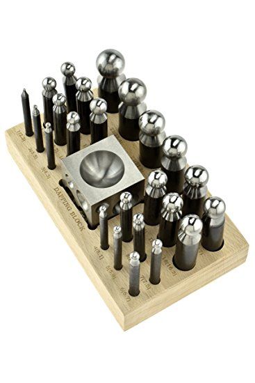
The set is a little pricey...I found a set on Amazon "SE JT3405DS 25Pc Doming Punch & Dapping Block Set with a Wood Stand " For $55.00.
The head sizes are...
24 punch head sizes (mm): 1, 2, 3, 4, 5, 6, 7, 8, 9, 10, 11, 12, 13, 14, 15, 16, 17, 18, 19, 20, 21, 22, 23, & 24
Hopefully the linkey works...
https://www.amazon.com/SE-JT3405DS-Domi ... B009ASXZHI
Re: M1A1 HA, 11/16 update, Raised Non-Skid Dimples
Posted: Thu Nov 17, 2016 10:49 pm
by BarryC


