Scratchbuilding C&Cs Mammoth Tank

Up to the end of WWII.
User avatar
Munty
Private
Posts: 90
Joined: Thu Mar 24, 2011 4:35 pm

Re: Scratchbuilding C&Cs Mammoth Tank

Post by Munty »

Well, it may have been a while since the last decent update (6 months this time!) but I reckon what follows is a good step towards making up for my most recent absence! Thanks going out to my friend Aidas who convinced me to crack on with the tank again rather than start off another random project! Hopefully he'll keep me motivated long enough to get it finished sometime soon!

Anyway, as I mentioned to Blimp in my last post I'm still looking for methods of reinforcement for the main body of this build while working on some interior detail in parallel. The first batch of images are all about the stuff I've got up to in the engine bay but it's still got a long way to go. The sandy colour is currently wrong so I'll hopefully be able to tone it down to the correct hue at a later date but this is only interior anyway so it matters very little... The left and right walls will eventually have fuel tanks on them but not sure what material to use right now (nothing jumping out at me from my bitz box) The rear wall needs detailing and will most likely get some lining, riveting and a door through to the forward compartment of the vehicle. Need to paint the second engine too and fabricate a central differential to join the two gearboxes. Final detailing will be a little wiring and such but I'm realising more and more how little of this area will be visible in the final build so I'm more focussed on the exterior right now.

So enough of the text,how about some pics? Here's the blank canvas before I started with all the hardware removed.
Image

This area actually has two different floor levels but both need elevating different amounts so here are the spacers for the lower floor to which everything will actually attach. Back wall is in place too but still isn't fitted yet.
Image

Here I've added some fairly deep lining to the floor and refitted it but it gets more attention before getting glued in.
Image

Here I used the remnants of a humbrol spraycan to paint the flat gray then a detailing pen for the lines. Dirty patches are watered down black paint, intended to show dirtier floor under the engines. It's pretty missable in the final build but at least I know it's there! Incidentally, I'm building this tank as a fairly new unit so it'll only have moderate signs of dirt, wear and use as I get into detailing...
Image

This is the floor with additional spacers fitted above it and the mesh engineering floor also fitted. It occurs to me that I think this is the first time I've shared images of this floor... It was completely hand made from rigid paper-coated florists wire which I glued together to form the thicker metal 'frame'. The fine vivarium mesh was then glued onto the frame after it got a coat of paint to turn it from green to silver! Then simply cut out the space for each engine and voila, the engineers crawlway! It honestly came out better than I could've ever hoped but now it's fitted I can't help but think it's a little too bright in contrast to the dark gray floor beneath...
Image

Anyone who remembers this project from a few years back will remember I altered the engine mounts to give them a little more realism (as they weren't intended to be visible in the T34 kit they're from) Now I did the same again to give them a smaller footing, something I can imagine being fitted in just such an application.
Image

I couldn't figure out how to detail the back wall or fabricate the fuel tanks at this point so I just gave a coat of paint to the interior walls here and then permanently fitted the main floor and all engine and gearbox stands. After test fitting both powerplants and boxes you can get a pretty good idea of how this space will end up looking. Not too bad but I feel the silver floor is too bright and shiny now... Will look much better once I get in the fuel tanks and some detailing on the rear wall. Will fit some dull lighting in here and I think it'll look just right when it's done. Just wish it was more visible! I've decided to scrap the mesh for the rear grill piece. Fitting it would make all this hard work even more missable! Will probably fit removable grills to the top of the hull too which will allow me to show it off a bit. Would also allow for simple engine removal in a real world application to be fair!
Image

That's by no means all I have to show for the last few days (not even the start of it I'm pleased to say!) but I'm going to pause now and make up another post for the next update as it's very picture heavy and is very seperate from a bit of hidden detailing! Also my children are nagging me for food or something similarly trivial... Will put them back in the cage then post the next update!
User avatar
Munty
Private
Posts: 90
Joined: Thu Mar 24, 2011 4:35 pm

Re: Scratchbuilding C&Cs Mammoth Tank

Post by Munty »

Ok, this is the much more interesting update you'll be pleased to hear! I am of course pleased with how the engineering bay is coming along but nothing quite compares to the bits and bobs I did next... I'm just going to get right to it so here they are!

I decided the turret had been looking like a hideously mis-proportioned blob for too long so the first thing I did was give it one of it's more unusual features as a tank. This first shot is of all the pieces cut and ready to go together.
Image

And here's the shell built around some florist block foam stuff... This is the 'dry' stuff as opposed to that more frequently encountered green absorbent stuff. It's basically there to provide some extra support for these parts as there will be some other internal structures going in later and I highly doubt they'd work with just the styrene... (You can actually see the plans for these things under the parts themselves!)
Image

Here are the end parts of both assemblies with the necessary holes all partially drilled. They're currently up to about 5mm IIRC but need to be more like 13mm when I can find a suitably sized drill! Unfortunately a few of these are a little off-centre which may end up making this look atrocious but I'll cross that bridge if and when I come to it.
Image

And here they both are, the Mammoths Tusk rocket pods! Sadly they prove to have a similar problem with scaling as the cannons do as they're apparently meant to be 60mm rockets. The 3D model being used as a template causes them to scale up to 208mm though, and that's being reserved about it... At this point I'm not going to be bothered by it anymore, they clearly didn't care about this stuff when they made the game. Apparently noone considered the implications it would have on a 1/16 scale RC scratchbuild 20 years in the future. Shame on you Westwood...
Image

This little bit of genius (can you tell I was chuffed with it?) is how the pods will be able to retain limited rotation after fitting but still be able to hold their selected position AND be removable in future if necessary. What you're looking at is basically a pair of rubber door stops with a machine screw running straight through them. There's a washer on both end to keep it from destroying the plastic and I tightened them up just enough that the rubber grips but still allows for rotation. Turned out to be very functional so far!
Image

Here they are fitted but of course the ends aren't on yet as I can't drill them out to the right size. I had to remove the furthest side of the turret assembly to allow for fitting these parts so that back turret is actually not firmly attached yet (still in fact)
Image
Image
Image

The next step in beautifying the turret isn't actually documented that well for some reason but I have an abundance of mockup shots so here's what I do have anyway! First up as always, it's the pieces I needed.
Image

And here are both sides built up, it really was that easy!
Image

And now I'm pleased to report a very serious development. That last image marked the beginning of bringing the Mammoth to life. Here come the guns...
Image

I picked up some 13 and 22mm pipe from a local DIY store and I think they're good choices (despite both being slightly undersized scale wise) That gives me a final diameter of 14" (350mm) externally and allowing for a 1.5" barrel thickness the internal diameter comes out at 11" (280mm) more than twice the size of the largest tank mounted weapon in history and a very common armament in cold war Russia (the ficticious designer of this vehicle) perfect!
Image

After those last shots I had to go away for four days and I was gutted to leave at such an exciting moment! It wasn't until I got back yesterday that I was able to drill out the turret to allow mocking up of the barrels in situ. It was probably far more exciting for me than it will be for you guys but it marked the high point of the build so far! Here's how the barrels are going to be fitted (with one more internal mounting point for added strength)
Image

These next few glam shots were taken before bed last night and I think the pods and barrels have just completely changed the appearance of this build. It's suddenly put the scale of everything into perspective and added a whole bunch of character to the vehicle. Of course, daddy would say that, see what you guys reckon!
Image
Image

Not too bad eh? But if you're still not impressed there's one last chance for me to bring you onside as we're not done yet! Been to a kiddies party this morning and doing guess what this afternoon?! Though it may be hard to tell, there's one part of the cannons still missing in those last shots and they'll help to align the guns as well as adding some strength to the whole assembly. Putting them together wasn't a big job but the angles were pretty tricky and the angles I had to file into the joins were particularly iffy so there are a couple of gaps here and there and these are by no means the strongest I've made so far! Here's the plan.
Image

And then it seems we jump past execution to a shameless showcase of all the funky holes and angles I've enjoyed over the last week! I had to use a carpentry drillbit for these which wasn't as accurate as I would've liked but it's all turned out pretty straight after some carving and filing to allow for the angle at which the guns pass through the 2mm sheet!
Image

Here's how the whole assembly will go together...
Image

And here it is having gone together! The barrels are much straighter and more uniform now, the thinner is not rigid pipe so this helps a lot...
Image
Image
Image

And finally!!! The last showcase for a while as I'm not entirely sure what my next job on this build will be... Here's a few shots of the whole build mocked up, starting off with...
IMAGE 300!!!
Image
301 is a better shot but that's not the point...
Image
Image

It's really nice to have come back to the project after so long and undeniably achieved such a lot. I guess the next thing I need to do will be the final internal barrel support in the turret. Then I can permanently fix the barrels and refit the side I removed for access earlier. That'll be the turret basically finished and it's already REALLY sturdy so no need for reinforcement there. Ah, there is the matter of finding decent metal pipe for the missile pods and a drill to cut through the ends there too... And of course I'll need some rockets too. The reason these pipes will be metal is probably fairly obvious. If you think you've got it then you probably have!

Got two more tracks left to make as well so I should probably tick off one of them soon as they're soul destroyingly tedious to do... Then it's all hands on reinforcing. I had a thought on that too actually after reading through basically this entire thread over the last week! It's down to a comment from Dylan who mentioned he often used plywood reinforcements in his builds. Now my tracks are odd shapes but I figure I can basically build a 3 sided rectangular reinforcement for each of these areas to fit perfectly inside the styrene. Can reinforce the corner joins easily if it's made of wood and the odd angular space that will be above the new section can be filled up with some foam or more of that florist block material (anything semi-rigid really!) Added bonus with this method is that the various axles I need to fit will have an extra few mm each side to call home.

So actually it seems I have plenty to do... Will have a think this evening about the order in which to do them all!

BEfore I finish up this post I wanted to say a few thankyous after re-reading this thread.

First up, thanks to rctankwarfare for giving me somewhere to discuss my crazy ideas and help me along the way!
Next up is Dylan who helped direct me to Trylon for styrene sheet. I couldn't have even started off if it weren't for their low prices.
sassgrunt gets a mention for supplying me with an awful lot of hardware, without which I couldn't even have begun putting together tracks and driveshafts! (I owe you $$$ too!)
sassgrunt again if I'm reading my pms correctly as it seems he gave me the engines AND the track bits! (I guess I owe you more like $$$$$$ then?)
Thanks go to Chris3 for the great job he did on my rear grill. It was a paid transaction but was well worth it so just wanted to tout the guy a bit :D
Also thanks to Blimp just for being Blimp. You've been here every step of my journey so far and I hope you stay till the end!
Almost forgot Nothgrin (if he's here somewhere) as without his suggestion regarding my drive shafts I'd probably still be pondering it!
Finally thanks to everyone else who's watched, advised, encouraged or just generally commented on the build. You keep me going even when it gets hard and boring!
I hope that's everyone but I started this thing years ago so apologies if I missed you, it's hard to figure out exactly where all this stuff came from this late in the day!

Cheers guys, hope you enjoy da gunz! Tim
User avatar
Munty
Private
Posts: 90
Joined: Thu Mar 24, 2011 4:35 pm

Re: Scratchbuilding C&Cs Mammoth Tank

Post by Munty »

Ok, so I have an update here if I can get a word in edgeways in here. Seriously, you all need to calm down before someone gets hurt :|

Anyway, my friend is so far continuing to keep me focussed on this project and progress has been continuing steadily for a while now, despite much of that progress being headscratching, blueprinting and mock-ups... See I'm up against the hardware right now so I'm trying to figure out how to fit the tracks which is proving an intersting yet particularly difficult task! I still only have one of the four drive shafts completed but now have 3.5 of the 4 tracks fully completed which is great. I've also had all of the sprockets I have drilled out to 10mm by a local machinist (couldn't hold them steady to work on at home and I like having all my fingers) so that's allowed for a recent burst of productivity. I think I know how to carry on from here but I seem to have run out of money right now so am using the pause to ask for any tips on here if there are any!

Got some pics to add of the progress I've made so far and it's all pretty encouraging stuff so hope it's of at least mild interest and PLEASE comment if you feel you have anything at all to contribute. A message board without messages is just a board, and boards are pretty boring...

This first shot doesn't show much new but you can see I've finally decided on where to put the other sprockets in each track which will of course determine the ground clearance I end up with. You can also see that by virtue of the design method, these sprockets will be unsprung. Right now I just want to get everything together, functional and solid...
Image

This next one has just confused me due to it's orientation. I'm currently working on the hull upside down as shown in the previous image. This image shows INNER support piece of the front-right track, confusing as I've got used to it being front-left while topsy-turvy... Anyway, this shot is just to illustrate the reinforcement I'm building into the tracks as I figured the whole build would be doomed without some! It's essentially two triangular wedged sandwiched between some thin ply. The hope is that there will be significantly less space for these assemblies to flex with this extra support built right into it. This shot is somewhat mocked up...
Image

Here you get a rough idea of how it goes together with the track in place too. Top left will be the drive shaft and other two holes represent the other sprockets that will help run the track. I'm considering reversing the location of those wedges right now as it makes the bogeys a bit tricky to get right but that's further down!
Image

It just occurred to me that the rest of these images might be better if I turned them the right way up but I can't be bothered so please feel free to turn yourselves upside down if you have trouble making them out! This is how the assembly all goes together...
Image
Image
Image
Image

You can see how there's space in the middle there for the other wedge shaped block but I think to allow for the slack track up top and bogeys down below it may make sense to swap them over... That's where I'm up to right now and I've been trying to come up with a solution to that one today. You can also see that this thing is going to be a massive failure without the aforementioned bogeys so it's a pretty big next step. Here's the 17cm gap between the sprockets right now!
Image

I initially wanted two twin bogeys and really would have liked them to be sprung but hey, things change! The sprockets won't be sprung anyway so there's no point putting a lot of extra effort into making something weaker than it needs to be! I'm still wanting four wheels though as that's how the tank appears in most of the official art. That gives me problems as The largest they can be is 38mm across but this gives them mere millimeters of clearance from each other. However, this is the only size I can easily attach with a simple 'rod thru hole' technique like the larger sprockets. I kind of liked this idea as it's simple and pretty strong but 38mm is too big and any smaller diameters will have their center hole BELOW the edge of the track armour.

So follows my current plan... I scoured the house for small round objects and decided that 32mm (a connect 4 token) seems to fit the bill size-wise pretty well! Gives about 6-7mm between each one which is plenty I think. Of course the hole is too low for simple attachment so I'm thinking two double bogeys (or whatever the non-golfing term is) should do just fine. By branching both wheels off one central piece it allows me to position them low enough to be useful while also giving me a pretty easy way to attach them to the rest of the assembly with some decent strength. My current thoughts are either the rod thru hole one which could be implemented once per pair of wheels, or to actually perma-fix each pair to the central wooden block inside the assembly. The former could allow for some minor movement but I want to avoid messing around with springs and such right now so may be easier to just mount them solidly... Here's some food for thought either way!
Image
Image

Also, I have a swap request if anyone can help me. I'm currently in need of a further 6 of these big King Tiger sprockets. They need to be metal and the same as the ones I've used so far but there are two different kinds I've come across so far and only one of them is good. This old comparison shot shows the difference between round and square peg variants. The ones I need are the square ones (on the left) but I have six of the round ones to trade in return! Please let me know if there's any way you can help, ebay isn't a cheap enough option to consider right now!
Image
Image

The next step remains the bogeys as without them in place I'm not willing to assemble the rest of the track. I also need to fix the sprockets to their respective axles and then trim said axles to their final length. So all in all a fair bit to do... Hoping to track down suitable material for the bogeys tomorrow. I'm planning to find a wooden broom handle or similar with the correct diameter and then cut it to length, groove it where necessary for the track guides and destroy a rubber inner tube to cover the contact faces. No idea how I'll stop the wooden faces looking like wooden faces but hey, I never said it was a perfect plan!

Please let me know any thoughts as I'm still very much making this up as I go along. Seems to be going surprisingly well so far but that's not the point...
User avatar
Munty
Private
Posts: 90
Joined: Thu Mar 24, 2011 4:35 pm

Re: Scratchbuilding C&Cs Mammoth Tank

Post by Munty »

While I am acutely aware that I'm the only person still writing in this thread, I'm going to keep going with it as I'm currently referring to my old posts almost daily for one reason or another! Got another really promising update today but mostly fairly boring pictures. It's a part of the journey where you really have to be invested to feel the actual impact of it but for me it's been a pretty big moment!

Apologies for boring pictures but hey, it is what it is! This carries on directly from the end of the last post (but with a little funding boost for bits and bobs!) Below are all of the parts I used to make the bogey wheels; you can see the plan changed from using lengths of rod to using individual disks which was definitely a good call. The larger wheels have been recycled from some leftover pieces of laminate flooring I had and DAMN is that stuff tough! Had to shell out £15 on a brand new hole cutter just to make it through and even that finds it hard! The smaller disks, made to allow for the teeth on the track, are cut from thinner and significantly easier to work with material!
Image

The previous image shows half the parts for one track so this is only 1/16th of the final part count but the only bit that's hard to make is the one I used the tough wood for! Below is a completed bogey, and yes it is very wide! Bear in mind, this doesn't really look or function much like a conventional bogey wheel but it'll hardly be visible in the final build so it's largely there to increase the footprint of the tank and reduce stress on the idle sprockets.
Image

Here's how it'll run on the tracks, got about 1mm of space either side of the outer most teeth.
Image

And here they are in a sort of semi-mockup state. They're currently higher than they will be in the final build as they move inside the armour soon...
Image

Seems I stopped taking pictures for the whole morning after this as the next shot I have has seen things change a lot (not to mention another visit to my DIY store!) I've now cut some brackets to hold the four bogey axles, trimmed the shafts down and fitted it all together with self tapping screws. They were one of very few possibilities I could think of and they worked a treat. The first prototype of this little train carriage mount (which my children kept stealing to play with!) actually had the brackets fitted outside the last wheels on each side but it really didn't look right. In the end I removed the two outer spacers and fitted the brackets there instead. It looks much more bogey-like now and will allow for some more detailing later which is good. Also visible in this shot are the new 'tyres' which are actually made from nice black electrical tape. I messed it up a few times but soon got down a good system of covering the things and it's both smoother and a lot better looking so that's a good result too...

Word wall aside, the main purpose of the following shot was to show just how much sag there is in the top of the track, far more than expected!
Image

Clearly that design isn't going to work at all. In either direction. At any speed. Ever...

So here is the revision that solved all of that. I also swapped out the small wooden wedge that I fitted earlier at this point and changed it for the bigger one.
Image

The previously fitted smaller one is now here...
Image

And the whole assembely now fits together like this!
Image

And a clearer shot without the nappy box. I made it so I could keep tension on the track while still having access to the space inside it. And no, it's not a box of 99 nappies, only 66...
Image

Here's what it will look like once everything is all together. Mostly anyway...
Image

And after another lapse in picture taking, this is what it really looks like now it's together!
Image

The first fitting of the carriage had it sitting too far inside the armour so it wasn't in contact with the track and hence left too much stress on the sprockets. It was also sitting a little too far forward so I took care of both those issues today and now it sits perfectly. I have one more screw to whack in there before the bogey assembly is truly secure so I'll pop in a pic of that when I do it as you can't really tell how it's fitted from these pictures but it certainly is!

I've also neglected to post any images of the idle sprockets it seems which were cut to the correct lengths and perma-constructed this morning in several unusual ways...

The wooden inner-assembly that carries all this gubbins is now solid as a rock and both my boys have had a wail of a time 'playtesting' it for me today. It's been a massive confidence boost and I can only imagine how different this thing will be when all four are finished. I'm going to be adding a little more reinforcement to the wooden assembly itself and then everything will be bolted to the main hull for one last bit of support so I'm really gaining some serious confidence in this thing right now. It's becoming more and more clear now that the plastic shell I initially built is actually the weakest outermost layer and now I'm adding the bones to it's inside as I go to ensure any weaknesses can be accounted for elsewhere.

It's worth noting that if I could power up the gearbox on this corner of the tank right now, this track would run... That's why I'm so excited about the result of this week's work! And like always, now I've done it once, all I need to do it exactly the same thing three more times! No more headscratching or prototyping, I KNOW how to make this work now and I have multiple templates to boot. Sadly I'm away for the weekend but I'm hoping to get most of the parts I need for the other corners cut tomorrow while my youngest is at nursery and I should probably finish that last track too! Of course I can't finish the last two corners until I can get a swap for some of these other sprockets I have so PLEASE help if you can!

One last thing befor eI log out for the night...
Image

Oh yeah!

And yes, it's still just as big as it used to be...
Image
User avatar
Wildboar44
Corporal
Posts: 392
Joined: Sun Jan 13, 2013 10:28 pm
Location: Kent England UK.

Re: Scratchbuilding C&Cs Mammoth Tank

Post by Wildboar44 »

Now that my friend is a labour of love , I for one will be following this one for sure , thanks for showing 8)
Yesterday is our history, Tomorrow is an eternal mistery, Today is a gift, its why its called "The Present".
tankman

Re: Scratchbuilding C&Cs Mammoth Tank

Post by tankman »

Jaw dropping build, will be watching this one progress.
Alan
User avatar
wibblywobbly
Major
Posts: 6396
Joined: Fri Oct 17, 2008 9:30 am
Location: South Wales Valley
Contact:

Re: Scratchbuilding C&Cs Mammoth Tank

Post by wibblywobbly »

You might be the only one writing, but a lot of us are watching this. It's totally unique, and the innovation that you have come up with to solve the problems is brilliant. Keep the pics coming, this is an excellent build. :clap:
Tiger 1 Late
Panther G
King Tiger
M36 B1
User avatar
birger
Lance Corporal
Posts: 138
Joined: Fri Aug 16, 2013 12:08 pm

Re: Scratchbuilding C&Cs Mammoth Tank

Post by birger »

Woaw, that is an awesome job.

I am looking forward to the result, and I want to see that one moving.

Greetings
Birger
Fahrzeuge einsatzbereit: Tiger I HL 313, Tiger I Tamiya S33, Star Wars Tiger, Bergetiger
In der Inst: HL-PIII Lackierung, Vollkettenschlepper, Tiefladeanhänger
In Planung: MLRS,Crusader, KöTi, Jagdtiger, PIII, PIV,
User avatar
Munty
Private
Posts: 90
Joined: Thu Mar 24, 2011 4:35 pm

Re: Scratchbuilding C&Cs Mammoth Tank

Post by Munty »

Thanks guys, it's nice to know people are still out there watching progress on this build! Please don't feel you need to be so quiet in the future, especially if you think you have any hints, tips or general advice that may help me along the way!

Anyway, I actually got the second set of axles done just before my weekend away and also have all of the wooden parts cut for track no.2 as well. The fourth track is finished as well now so that job is completely finished now which is a load off to say the least! The new set of axles I cut are absolutely millimetre perfect thanks to the amount of marking and measuring they got so I think I'm going to redo the first set I did this week. The originals are a little short in places and also leave the track a little too close to the hull.

Next job will be to build up a second bogey assembly which will allow completion of the second track and then I'm kind of stuck until I can source some of the drive sprockets I need for the other ones. Got a few leads on ebay which I need to follow up but not long been home so having a brew first! I think probably the next thing I'm going to do will be the armour plating on the tracks I've already finished/nearly finished. Although the whole build is coming together brilliantly with these tracks getting added, the main body itself is still a very bland expanse of white so I'd really like to see how it looks with the first layer of detailing in place!

For now that's enough as my cuppa is going cold and I need to fire off some e-bay-mails to secure my new sprockets so goodnight for now and I hope to be able to post an armour update soon. Cheers, T
User avatar
Munty
Private
Posts: 90
Joined: Thu Mar 24, 2011 4:35 pm

Re: Scratchbuilding C&Cs Mammoth Tank

Post by Munty »

Right folks, back again, though with a distinctly mixed feeling on my recent progress! While I'm really pleased that things are still moving at the speed they are, the need to do every single job four times before it can be officially called finished is rather disheartening at times!

Right now I'm pleased to report 90% completion of the second track assembly and final assembly of the first one! I've also managed to order the remaining 6 sprockets I need but they'll be a few weeks coming so the other two tracks will have to wait for now... That said I can still get on with preparing the wooden parts and putting together some of the reinforcing structure while I'm waiting for them so I'm by no means at a standstill. I also have one of the two rocket pods still to finish but I'm fast running out of cutting discs and don't want to risk breaking my last one before the backup I ordered today has a chance to arrive!

Another pleasant development is a little of the final skin, currently just two of the armour plating pieces for the completed tracks. It still doesn't do a great deal to help with visual scaling (read - still looks like a 1/6 build :haha: ) but it's a welcome start and at least a start to covering some of these big white spaces!

Anyway, I'll show some pics of these bits in this update later so no need to explain it in writing! First up though, I took a few additional shots of work I did a while back that never got a decent showcase.

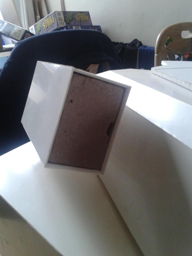
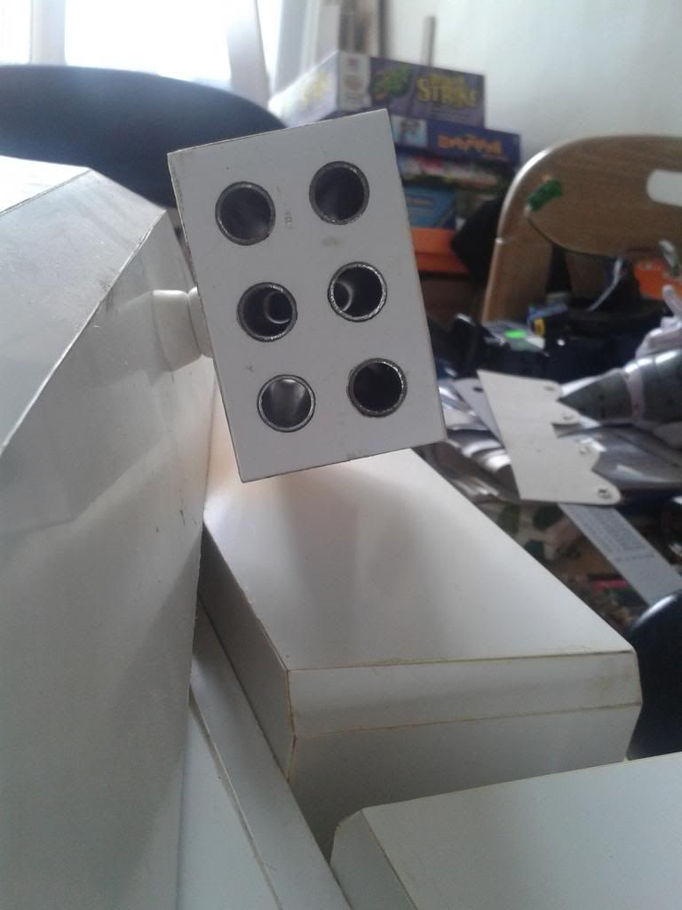
First up here's that rocket pod I still need to work on. It's appeared in previous pictures so nothing new here...
Image

Here's the finished one, it's also appeared before but now it gets it's own spot in the lineup! The missile tubes are something like 12mm pipe and whatever material I used happens to be rather tough and heavy so the next one will have to wait a while if I want to cut it nicely. On the other hand I have considered just doing it the old fashioned way with the hacksaw and bench-grinder so that's always an option!
Image
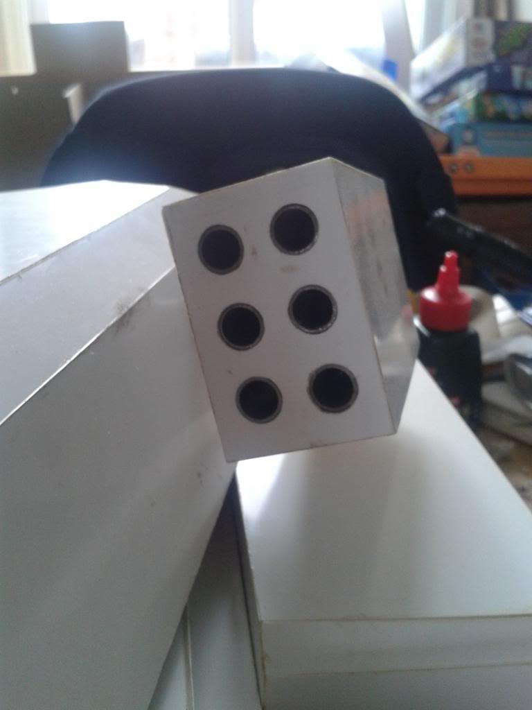
As you can see here I've just left all the tubes as empty for now. They'll be addressed much further down the line when I start thinking about dramatic pyrotechnics :)
Image

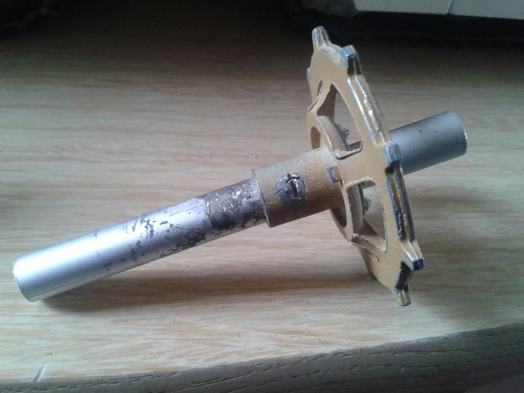
The other assembly I haven't showed since I finished it is the 'idle' sprockets that will run on the ground. I had a few thoughts about how to put them together but with my limited resources and very basic toolbox I figured this was the easiest way. BEsides, I've always wanted this tank to be a simple dismantle job after it's finished for repairs and upgrades later in life so I stayed with that philosophy here too.

First up, the gear face is simply bolted to the axle at the correct position with the excess bolt being cut off. I then slotted one end of the bolt to allow future removal. This was made necessary by some poorly measured axles anyway so isn't as forward thinking as it may seem! Remember I said the first track I finished was a little off-centre? I recut all those axles to fix the problem and hence needed to remove these bolts...
Image
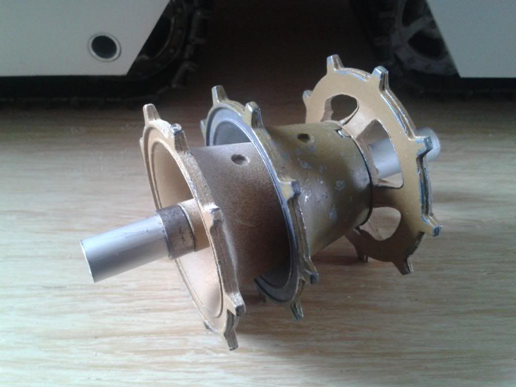
After this part of the assembly is secure it's a simple job of sliding on the two rear sprocket pieces and finding a way to secure them. It turned out to be impossible to use another bolt here so instead I cut some of the pipe I'm using for the missile tubes and used the small pieces as collars. The diameter of the two pipes makes them a perfect fit so I simply smashed it with a hammer for a while, to create a slightly ovoid collar, then fitted it to the axle. After fitting I used a spare sprocket to hammer the collar right onto each piece and this stopped the unsecured rearmost piece from moving but I doubt it will last for long what with vibration and such. That's one of many potential issues that I'm happy to deal with later though, so for now they look like this!
Image

That was the only catching up I had to do so this is new stuff from here on out! I've spent a LOT of time recutting these axle pieces this week as I'm apparently overly anal when it comes to having my track run central. It's been incredibly frustrating as I'm working to a tolerance of <0.5mm but don't possess ANY tools that make that a realistic target! But of course the good thing about being overly anal is that I achieved that target anyway! We OCD types rarely take no for an answer...

Anyway, once I was finally happy with all the axles I'd built for the first track (read - prototype track) I finally decided it was time to fix it together as it will be in the final build! So here's one I made earlier...

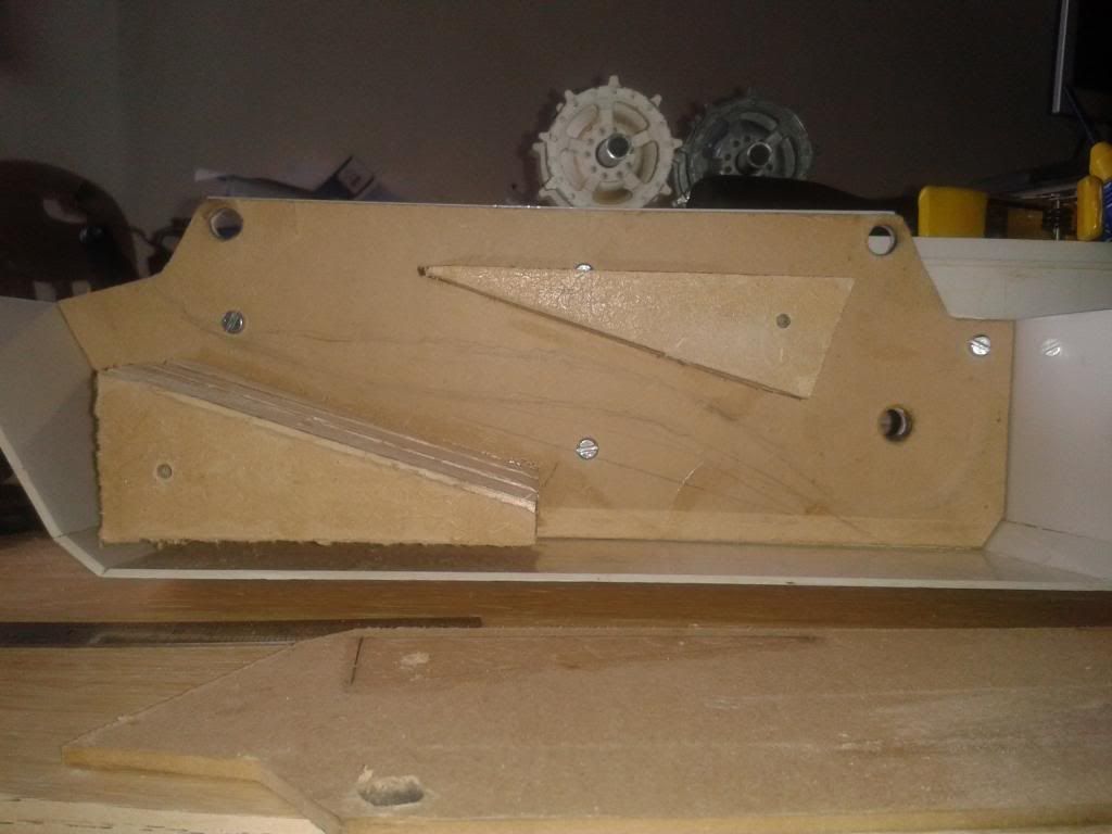
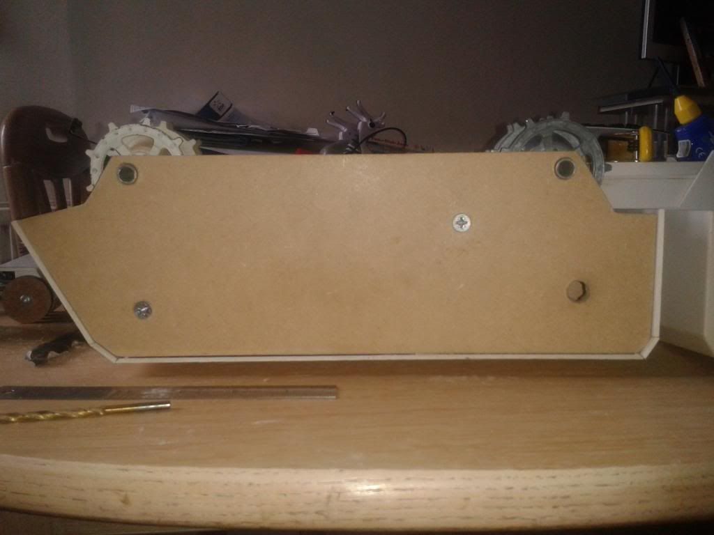
First off, remember the side piece was removed from this track a LONG time ago, it made life (and especially photography) a lot easier, but I won't be making the other 3 like this... What's new in this shot is that I've removed one side of the wooden reinforcement piece and added 4 easily removable bolts through the wooden structure, the track armour AND the hull itself. The main purpose of these is of course to add rigidity by sandwiching all the different layers together. However, it also allows for fairly easy removal of the wooden sub assembly at any time, even post build. In addition to that, I figured it makes it possible to actually remove the entire track assembly, axles track and all. I'd just need to remove the bolts and seperate the glue between the hull and track armour and any potential problems I may encounter in the future would become significantly easier to rectify.
Image

In this shot I've replaced the other side of the wooden structure both with suitable glue AND 2 long screws. These will help the sandwich structure retain it's strength once complete, although I forgot to place two on the other side before bolting it to the hull. This can easily be remedied at a later date. Both idlers are in place here but the drive axle was being remade at this point.
Image

This shot shows how the bogey assembly has been (temporarily) secured in place inside the track assembly. Notice it's been fixed to another piece of plasticard the full width of the housing to prevent sideways movement and a small clout nail is currently stopping it from moving during track motion. It will be replaced with a suitable screw once I get one from the shops! This shot also gives the best idea of internal construction too, and how much of what has been built will be invisible to anyone seeing the tank in a normal situation...
Image

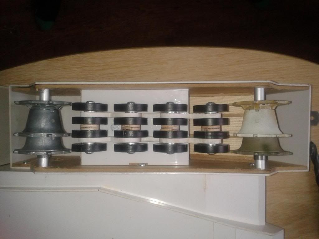
This shot is simply the bogeys mounted and the side piece attached WITH GLUE! Gasp... Yep it's finally on permanently now that I'm happy with the method for building these things! The pencilmarks on this piece are all wrong so can be ignored until you see the nexta image and realise what they are...
Image

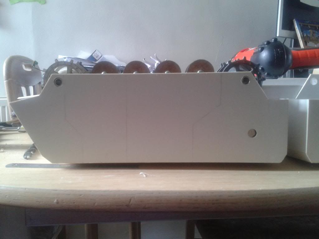
Yep, time for armour plating and it couldn't have gone any better! I for one think it's really great being able to see the whole assembly without the axles sticking through visible holes. It's basically 5mm foamboard (or similar) which I liberated from a building site when one of their signs broke in half. It's very easy to work with and I managed to get a really good fit from it. I sanded a 45degree chamfer onto all the edges, as this is how the tracks appear in official images, and then added some panel lines which I THINK are deep enough. I'm not going to change them until I decide how to add the plating to the other track surfaces. The trouble with adding more material to the other sides it that it will interfere with the turret height (not to mention these side plates I just finished... But for now this is a FINISHED track! The drive axle and track are in there and it's all PERMAFIXED! Of course the joy of this design is that despite this I could dismantle the entire thing in about ten minutes, but if I don't WANT it to come apart, it won't!
Image

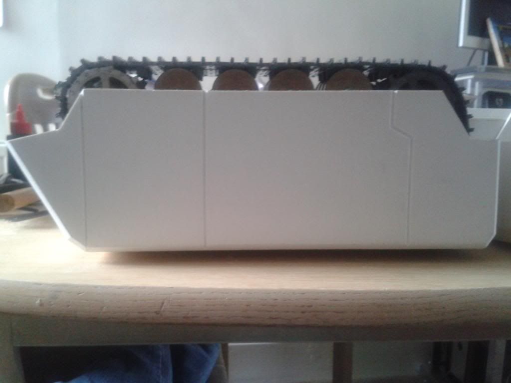
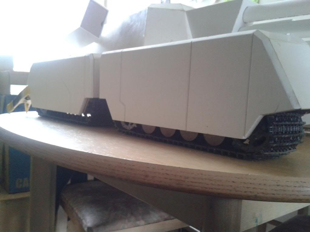
There's quite a lot of work going on between these two images but this is basically the rear track on the same side finished to the same extent as the front one save for the bogey assembly. You can see the side plating isn't glued here and it actually still isn't as it's harder to remove the rearmost idler on this track and I don't want to glue myself into a corner just yet! Once the bogeys are sorted though, this track will be finished too. I'm just putting off cutting all those wheels out again as it took ages last time...
Image

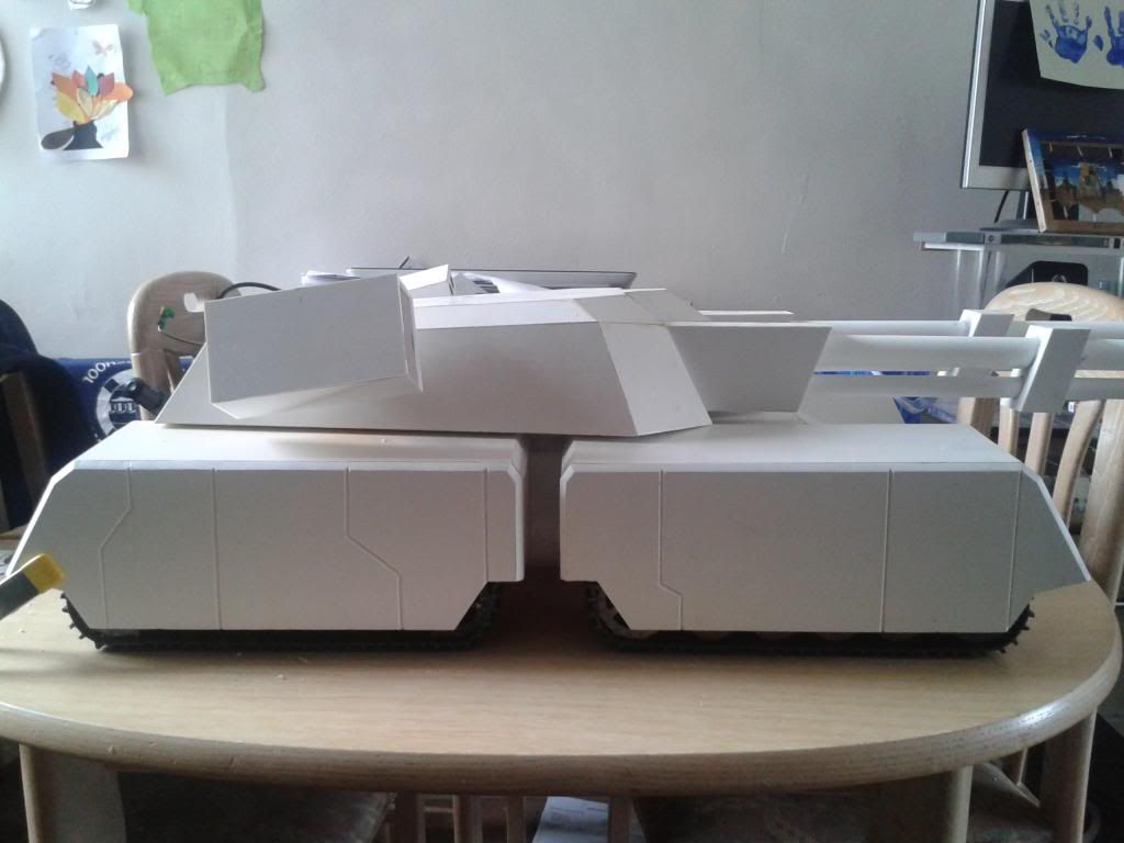
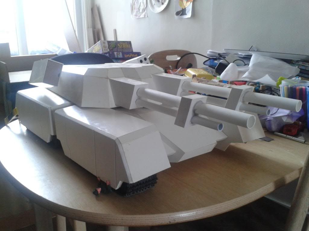
Here's a side shot of both 'finished' tracks and armour plating starting to make an appearance. I'm well aware that they're still huge and don't add much in the way of detail but I think they already make a HUGE difference to what was essentially a large flat white surface with holes in. And remember, all the surfaces will have at least SOME similar details on which will help a lot. It'll continue to look completely out of scale until I start adding things like shovels though I think! Also, please remember this is a faithful recreation of a tank that never existed! I'm trying not to take any liberties and as this is what it looked like in the game, this is what it has to look like now!
Image

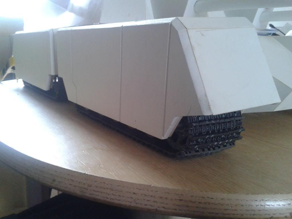
Gratuitous track shots... Think the plating looks better when your eye isn't drawn to the rest of it which still looks pretty crappy by comparison... Bear in mind that those bogey wheels need some sort of detailing before I consider them finished. I like wood as much as the next man but not for tank wheels!
Image
Image

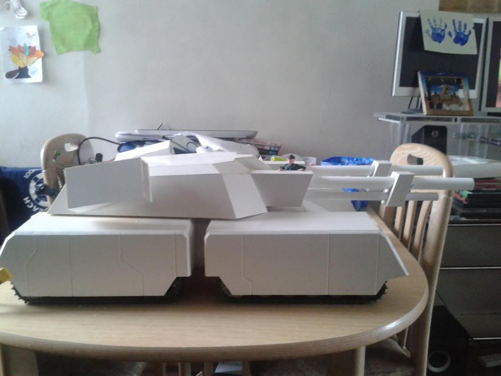
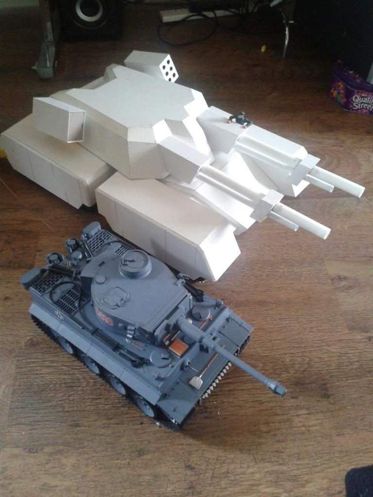
Added my Tiger Commander for scale, and while he does look hilarious I think that's about the scale I was looking for! Hard to know since he has no legs. Especially in the second image...
Image
Image

And now for the first time in a year and a half, some scaled comparison shots! Here's the Mammoth as she stands now next to the little old Tiger...
Image
Image
Image
Image
Image
Image

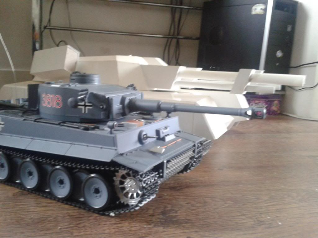
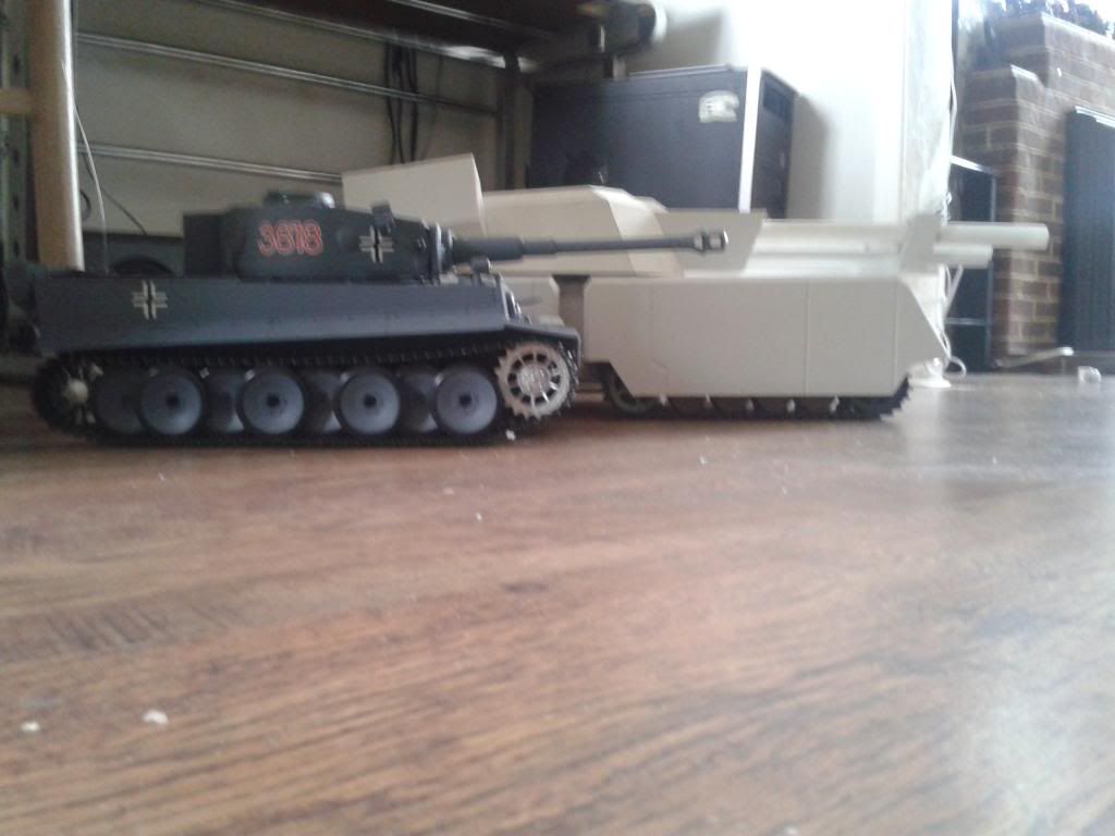
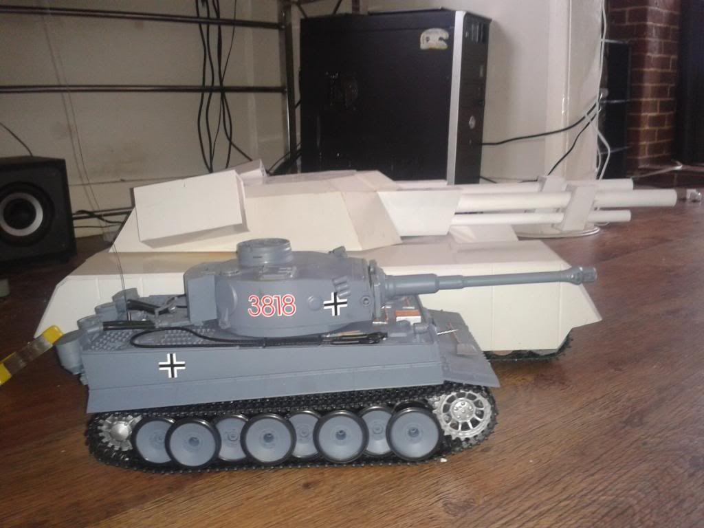
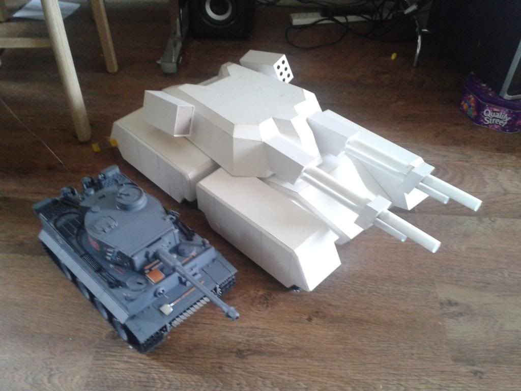
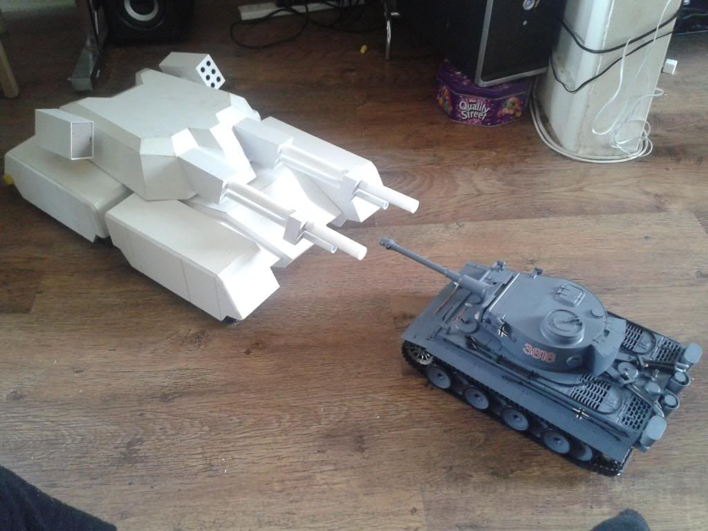
Hope you like it, how do you reckon she'd look on a 1990 battlefield? I'm betting it would make quite a few tankers pretty nervous myself! Not sure what the next update will be while I wait for bits and pieces but rest assured you'll know when I do!

NB. Almost forgot to say, I've seen this thing run ;) I made one of the drive axles without cutting it to length and then ran it with a power drill but couldn't really get a video of it as I couldn't support the weight of the track! It wouldn't be an issue now as all the reinforcing has been done and I can now LIFT the thing by it's tracks (very different from a week ago when I could hardly lift it anywhere at all without damaging a join!) but sadly I don't have a long drive shaft anymore... I'll make up another long one when I can and try to get a video now it's looking a bit more finished but I tell you what, it was pretty damn good! As you'll know, I already have the gearboxes in place but not the rest of the hardware to make them run so I'm wondering if it's possible to get the gearboxes running directly from a battery somehow? Just whack some wires in there and create a closed circuit? I can take the battery from my tiger but sadly the controller seems to be dead for it (otherwise I was going to rig it up to run from there!) Any advice on this would be great and also allow for a video of both tracks moving together, something even I haven't seen yet! Failing that I recokon I should have all four tracks done within a month (or Christmas at the very latest!) so fingers crossed we'll see something interesting soon!

Cheers for looking, please tell me what you think. Do the cannons look too big yet? @)
Post Reply

Return to “Other”