Re: Scratchbuilding C&Cs Mammoth Tank
Posted: Wed May 25, 2011 12:26 pm
Woohoo! My package arrived today and Mike is now my best friend in the whole world! (Though he doesn't know this yet) He sent me even more than I was expecting so Christmas has come early in the Mammoth household today! I didn't want to update my postal situation so I have a little bit of formal brainstorming to share too. After pretty much deciding on the previously posted layout for this area, I'm now able to mock it up with the bits I got from Mike so below are some pics of my pressies and what I intend to do with them. Also enclosed is a request for materials and a few opinion based questions so please read on if you've got this far 
First my significantly larger than expected package! As you can see I couldn't contain the parts any-more than I could contain myself so I opened it before reaching for the camera :p

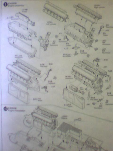
Also included by my beloved benefactor was a full copy of the instructions which just go to show how amazingly detailed this kit is. (I mean look at the size of the box I have and that's only a fraction of it!)
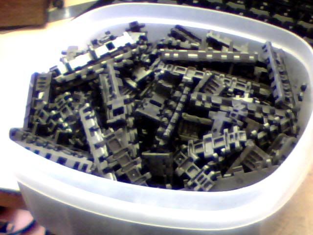
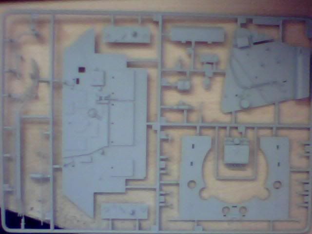
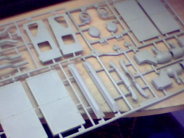
Enclosed were 2 of each of the following sprues, much more than I'd expected so even more to be grateful for! This first one has some compartment walls and other panels and wires and so on which will be great for final detailing.
The all important engine sprues!
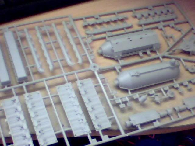
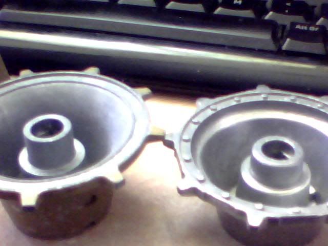
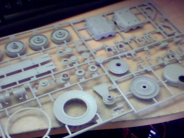
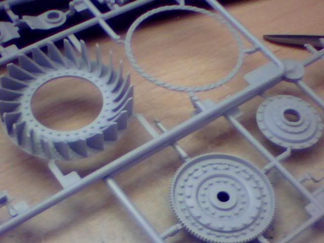
Radiators, air filters and other assorted parts (didn't think I was getting these but really happy I did!!!)
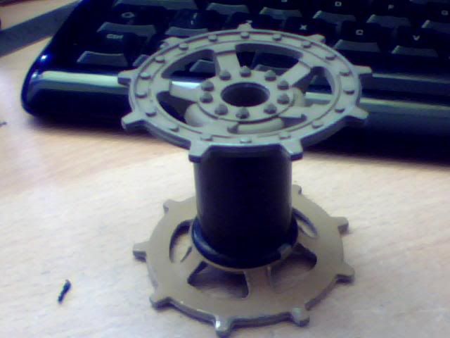
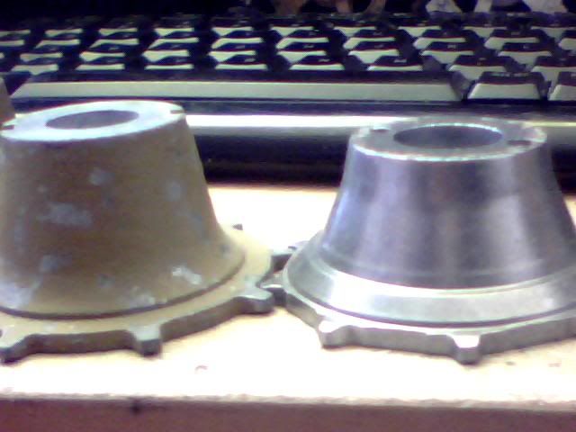
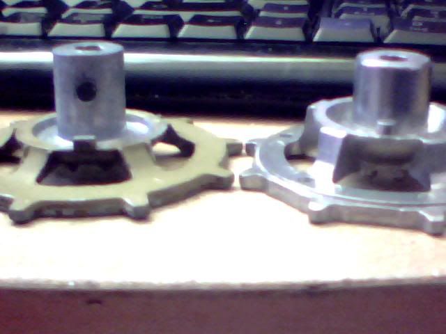
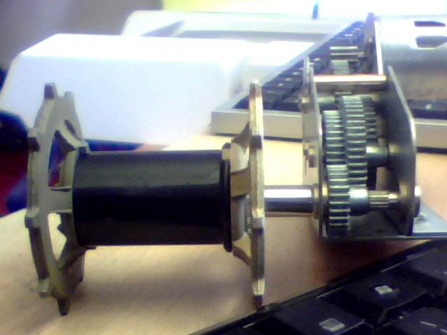
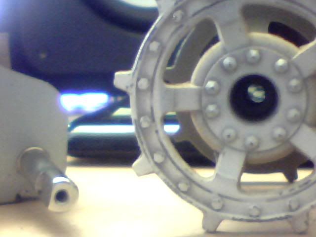
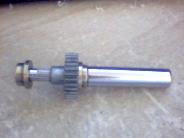
And lastly the gorgeous transmission kit. The flywheel itself is a work of art and there are so many detailed levers and motors that modifying these should be a breeze and a pleasure!
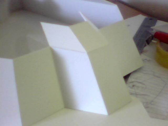
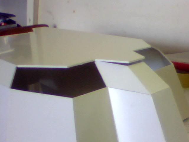
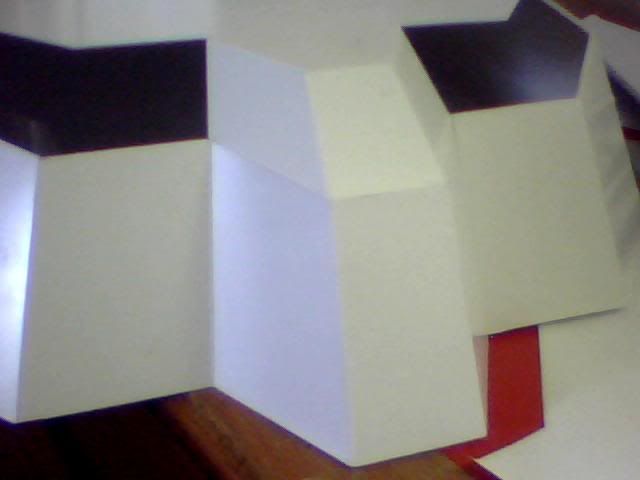
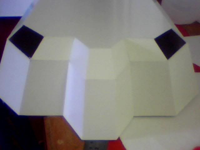
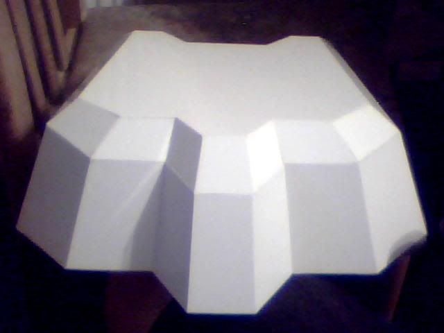
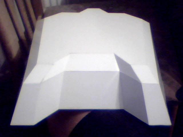
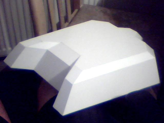
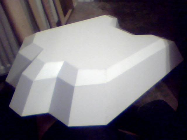
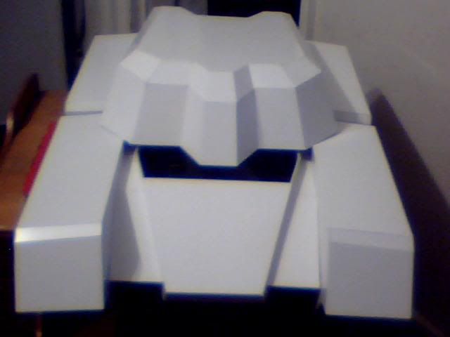
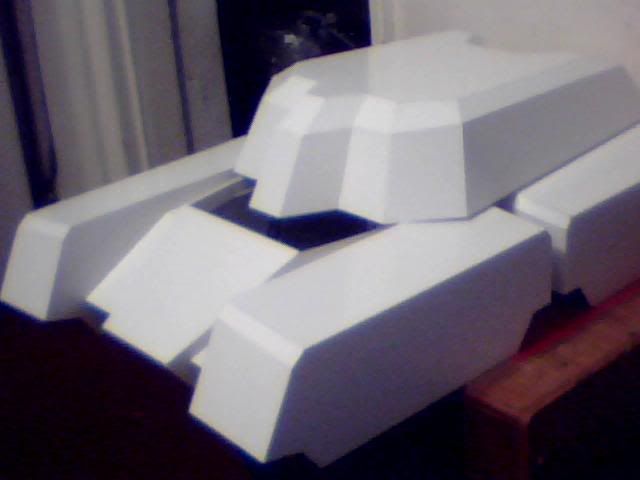
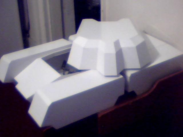
Onto some minor progress I made a few days ago while I was waiting for a friend of mine to visit. This is the back of the turret. It's not much but it's come out very well given the multiple nasty angles. The top of these 5 pieces aren't level which I guess is due to the angles but I'll fix that later as the final pieces for the turret will all be individually made now the plans are getting less reliable (nice and time-consuming!)
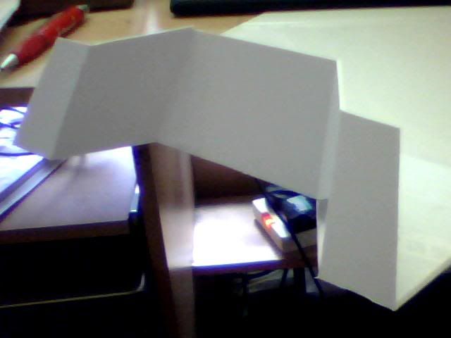
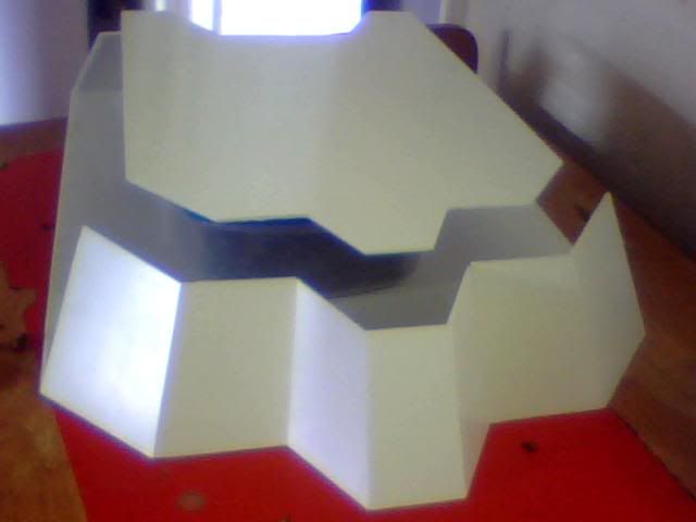
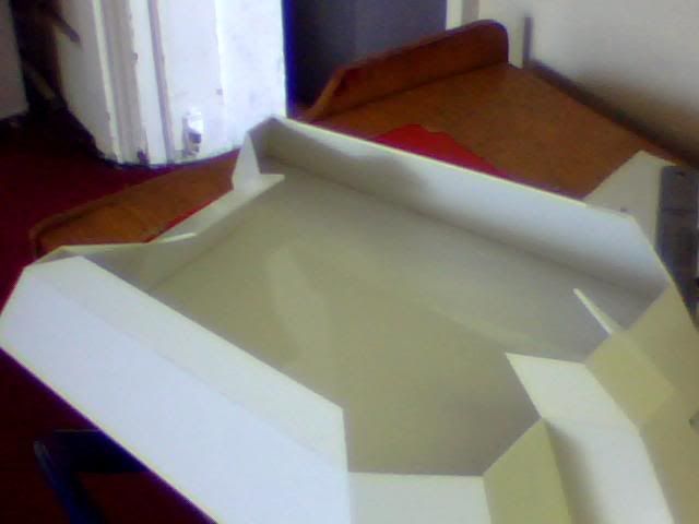
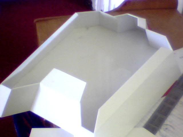
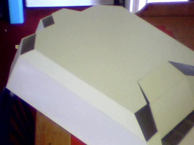
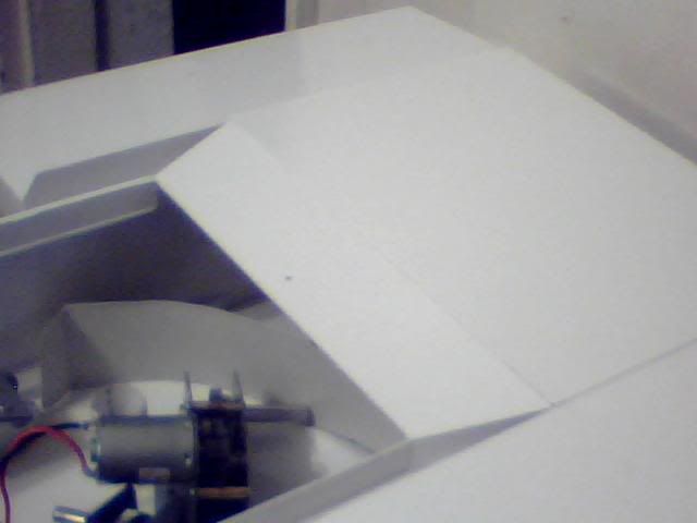
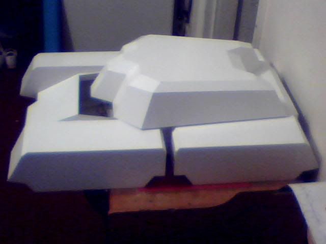
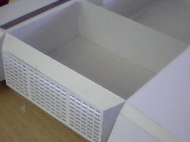
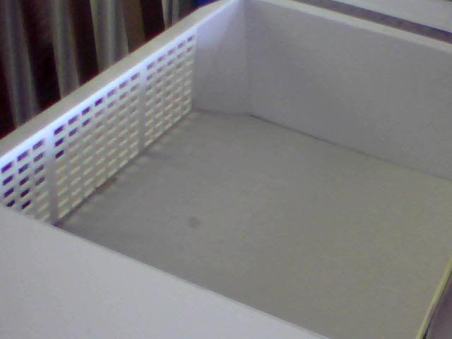
Now onto the engine room. First off, here it is in all it's glory...
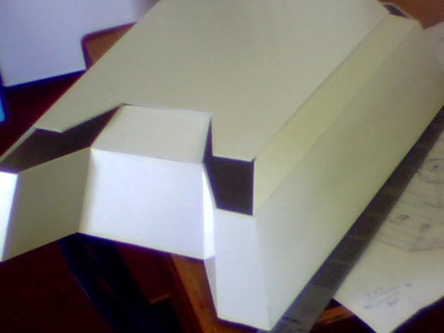
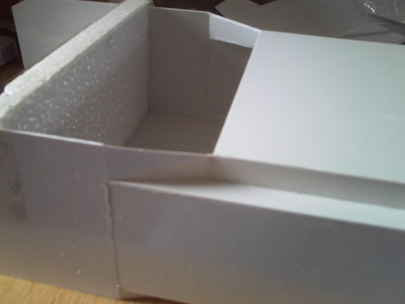
Obviously that's a lot of space to fill so just chucking some engines in there won't do the job. First thigns first I tried to wall off the excess space by chopping up a cereal box! Temporary measures only I promise... That gave me a new floor and lost about 25mm of height while also giving me a rear wall to what will be the only visible interior section of this build.
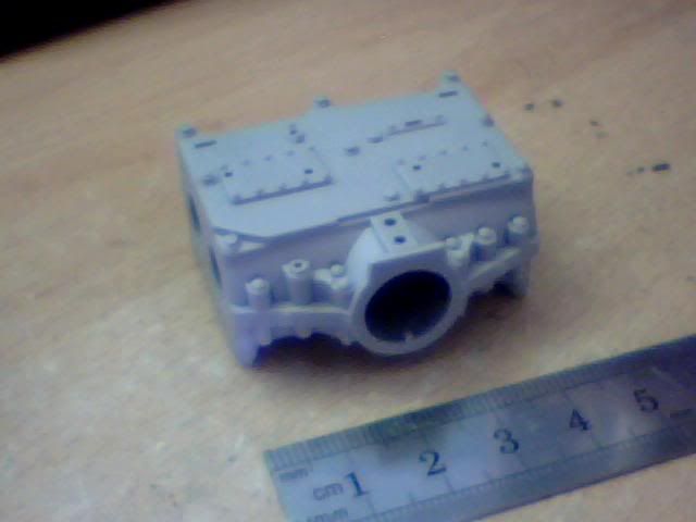
I just feel like I have to share a pic of this flywheel as it's so immaculately detailed. Tragically my camera won't do it any favours but trust me when I say it's got the details sown to the very last bolt head!
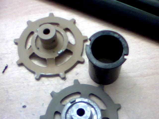
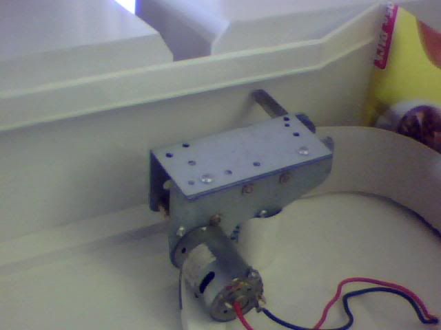
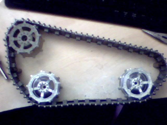
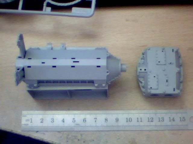
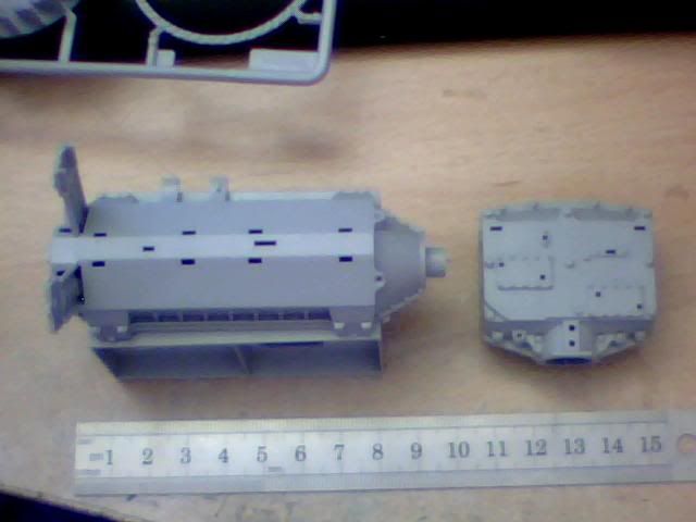
Now please don't anyone be upset by these next few images, they're only very early glue-free mockups!!! I'm certainly not going to dive in with this beautiful kit now that I've been so lucky to get my hands on it. The final build will be done very carefully and slowly to achieve the best look I can from this great little piece. That said, here are a few pieces off the sprue so I can get an idea for exactly how everything will look when finished (and also to help me decide on location and spacing and such!)
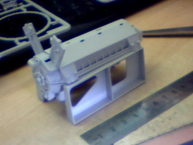
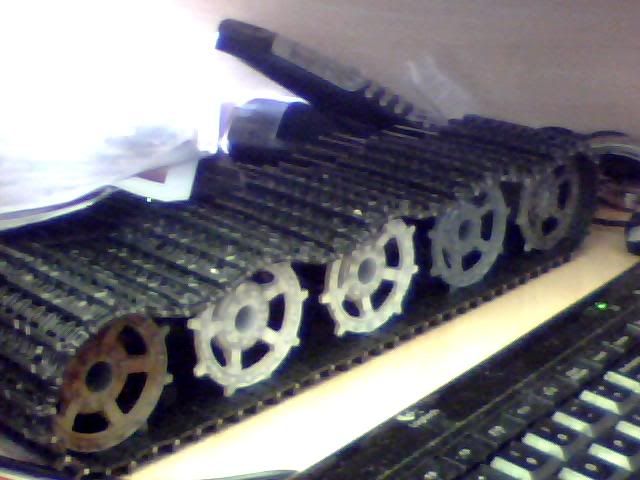
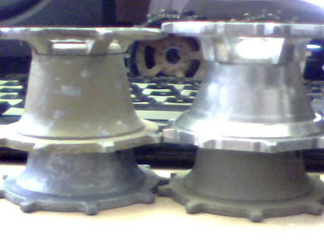
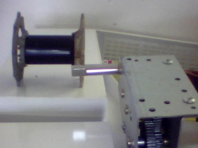
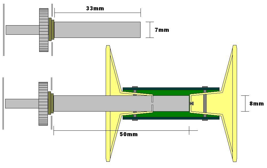
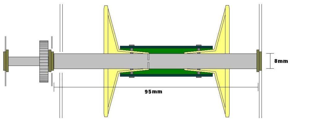
As you can see from those the engine is about 90mm long with the transmission about 50mm wide. For me, I won't be using the trannies in their standard configuration and instead, as already shared, will be mounting them lengthways in the vehicle. This is to represent a direct drive from each engine straight through to the tracks further forward and also one spur from each side which will meet in a transfer box at the centre of the compartment. This will have to be scratchbuilt but I have plenty of great parts to play with including all 4 transmission brakes which won't be used. Here are some shots of what the arrangement SHOULD look like adn what it WILL look like!
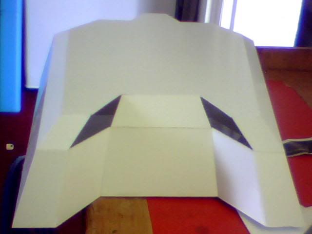
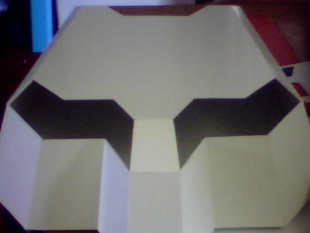
Of course the little gap in the middle will be filled with the flywheel assembly as intended, this is about 13mm when complete giving my finished unit a length of about 150-160mm from dizzy to driveshaft! Anyway onto the important part of how those two fairly small assemblies can hope to fill such a large void... I used the cardboard floor to draw a template for the interior but the details didn't come out great on the pictures that follow. The hole in which the engine is recessed is about 10mm below the rest of the floor while at the back, the transmission will NOT need a hole beneath it. That's one thing I now know which I previously didn't!
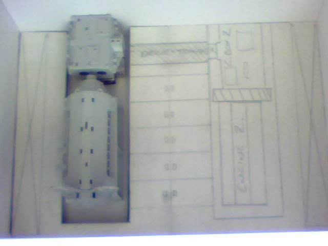
The doodling on the floor relates almost identically to the previous floorplan I posted with battery storage under the central floor of the engineers crawlspace and the fuel tanks provisionally marked in at either side. These are one of the things I'd like advice on though... I think it would be a pretty nice thing to have the tanks visible in this area as it's a good space for them and it'll save me trying to detail 2 big flat walls! They're behind the engines too so no need for dials and such there, just boring riveted panelwork probably... But anyway, is it a really stupid idea having them there? I think it would be passable, I mean anything able to detonate in the engineers compartment will also annihilate the powerplant, cripple the turret and kill most of the crew. With or without fuel in the proximity it's gameover once that area is breached... But is that just me? Can anyone reading this please lend me your opinion on the layout? Would be muchly appreciated!
Further to the fuel tanks, I now have the rads in this kit which I wasn't expecting! (Thanks Mike!) My initial thought was to put them right by the rear of the tank and have a crank driven fan on each engine to assist with cooling. It makes perfect sense from an engineering standpoint but it would block any view of the interior so I'm wondering what other options may exist. Not only for location of the rads but also for adding visibility to this interior once everything is done. I mean like grills and hatches and such so I don't want or expect it to be constantly visible. Then we're back in achilles heel territory!
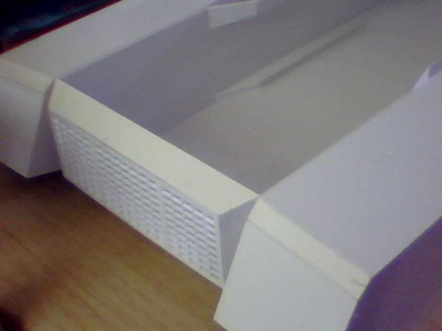
Working from existing plans limits my choices somewhat but obviously I have that large grill at the back which I'm yet to do anything else to (though still planning a finer mesh grill inside it which would greatly reduce both risk to the vehicle and visibility) And my other known feature of this tank are 2 elongated rectangular sections directly on top of this engineering bay. They look like chequerplate to me but there's no visibility with that! I was wondering about making them grills instead for a bit of ventilation for the engineer and maybe even cooling/intake (as I have intake parts with my kit) I haven't decided where to route the exhausts yet either but that's important as I have smoke and sound to install at a (much) later date!
Further to the chequerplate mention, I need a material for my floor in engineering if anyone has any ideas. I was looking for a sort of steel grate flooring so I could have visible batteries under those hatches at the middle but I'm not decided and either way I can't find anything really suitable! If not then I'll go with chequerplate in which case I need directing to a source for that in 1/16 scale (I know I've seen it in shops before so can't be hard. Worth asking here while I'm posting though!)
Finally a parting word on fuel tanks. I'm thinking I could make some really nice looking ones from real lead which I've used rather successfully lately for a wierd looking floor. It has the perfect colour and texture for an unpainted fueltank and it's easy to mark with grooves (as fueltanks so typically have) or anything else. Here's a shot of my last experiment with the stuff and this is on a 1:100 scale! Again forgive the poor quality...
I'm not going to dive into any further detail work until I have the turret finished and at least have some feedback so please let me know what you think as everything is easily changed at this point but it soon won't be!
First my significantly larger than expected package! As you can see I couldn't contain the parts any-more than I could contain myself so I opened it before reaching for the camera :p
Also included by my beloved benefactor was a full copy of the instructions which just go to show how amazingly detailed this kit is. (I mean look at the size of the box I have and that's only a fraction of it!)
Enclosed were 2 of each of the following sprues, much more than I'd expected so even more to be grateful for! This first one has some compartment walls and other panels and wires and so on which will be great for final detailing.
The all important engine sprues!
Radiators, air filters and other assorted parts (didn't think I was getting these but really happy I did!!!)
And lastly the gorgeous transmission kit. The flywheel itself is a work of art and there are so many detailed levers and motors that modifying these should be a breeze and a pleasure!
Onto some minor progress I made a few days ago while I was waiting for a friend of mine to visit. This is the back of the turret. It's not much but it's come out very well given the multiple nasty angles. The top of these 5 pieces aren't level which I guess is due to the angles but I'll fix that later as the final pieces for the turret will all be individually made now the plans are getting less reliable (nice and time-consuming!)
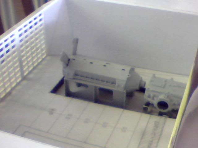
Now onto the engine room. First off, here it is in all it's glory...
Obviously that's a lot of space to fill so just chucking some engines in there won't do the job. First thigns first I tried to wall off the excess space by chopping up a cereal box! Temporary measures only I promise... That gave me a new floor and lost about 25mm of height while also giving me a rear wall to what will be the only visible interior section of this build.
I just feel like I have to share a pic of this flywheel as it's so immaculately detailed. Tragically my camera won't do it any favours but trust me when I say it's got the details sown to the very last bolt head!
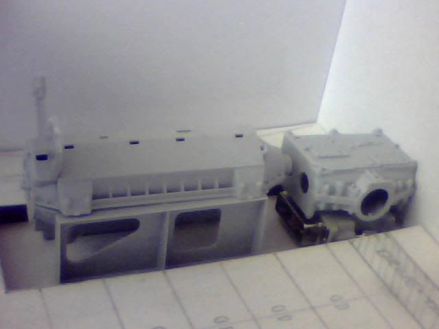
Now please don't anyone be upset by these next few images, they're only very early glue-free mockups!!! I'm certainly not going to dive in with this beautiful kit now that I've been so lucky to get my hands on it. The final build will be done very carefully and slowly to achieve the best look I can from this great little piece. That said, here are a few pieces off the sprue so I can get an idea for exactly how everything will look when finished (and also to help me decide on location and spacing and such!)
As you can see from those the engine is about 90mm long with the transmission about 50mm wide. For me, I won't be using the trannies in their standard configuration and instead, as already shared, will be mounting them lengthways in the vehicle. This is to represent a direct drive from each engine straight through to the tracks further forward and also one spur from each side which will meet in a transfer box at the centre of the compartment. This will have to be scratchbuilt but I have plenty of great parts to play with including all 4 transmission brakes which won't be used. Here are some shots of what the arrangement SHOULD look like adn what it WILL look like!
Of course the little gap in the middle will be filled with the flywheel assembly as intended, this is about 13mm when complete giving my finished unit a length of about 150-160mm from dizzy to driveshaft! Anyway onto the important part of how those two fairly small assemblies can hope to fill such a large void... I used the cardboard floor to draw a template for the interior but the details didn't come out great on the pictures that follow. The hole in which the engine is recessed is about 10mm below the rest of the floor while at the back, the transmission will NOT need a hole beneath it. That's one thing I now know which I previously didn't!
The doodling on the floor relates almost identically to the previous floorplan I posted with battery storage under the central floor of the engineers crawlspace and the fuel tanks provisionally marked in at either side. These are one of the things I'd like advice on though... I think it would be a pretty nice thing to have the tanks visible in this area as it's a good space for them and it'll save me trying to detail 2 big flat walls! They're behind the engines too so no need for dials and such there, just boring riveted panelwork probably... But anyway, is it a really stupid idea having them there? I think it would be passable, I mean anything able to detonate in the engineers compartment will also annihilate the powerplant, cripple the turret and kill most of the crew. With or without fuel in the proximity it's gameover once that area is breached... But is that just me? Can anyone reading this please lend me your opinion on the layout? Would be muchly appreciated!
Further to the fuel tanks, I now have the rads in this kit which I wasn't expecting! (Thanks Mike!) My initial thought was to put them right by the rear of the tank and have a crank driven fan on each engine to assist with cooling. It makes perfect sense from an engineering standpoint but it would block any view of the interior so I'm wondering what other options may exist. Not only for location of the rads but also for adding visibility to this interior once everything is done. I mean like grills and hatches and such so I don't want or expect it to be constantly visible. Then we're back in achilles heel territory!
Working from existing plans limits my choices somewhat but obviously I have that large grill at the back which I'm yet to do anything else to (though still planning a finer mesh grill inside it which would greatly reduce both risk to the vehicle and visibility) And my other known feature of this tank are 2 elongated rectangular sections directly on top of this engineering bay. They look like chequerplate to me but there's no visibility with that! I was wondering about making them grills instead for a bit of ventilation for the engineer and maybe even cooling/intake (as I have intake parts with my kit) I haven't decided where to route the exhausts yet either but that's important as I have smoke and sound to install at a (much) later date!
Further to the chequerplate mention, I need a material for my floor in engineering if anyone has any ideas. I was looking for a sort of steel grate flooring so I could have visible batteries under those hatches at the middle but I'm not decided and either way I can't find anything really suitable! If not then I'll go with chequerplate in which case I need directing to a source for that in 1/16 scale (I know I've seen it in shops before so can't be hard. Worth asking here while I'm posting though!)
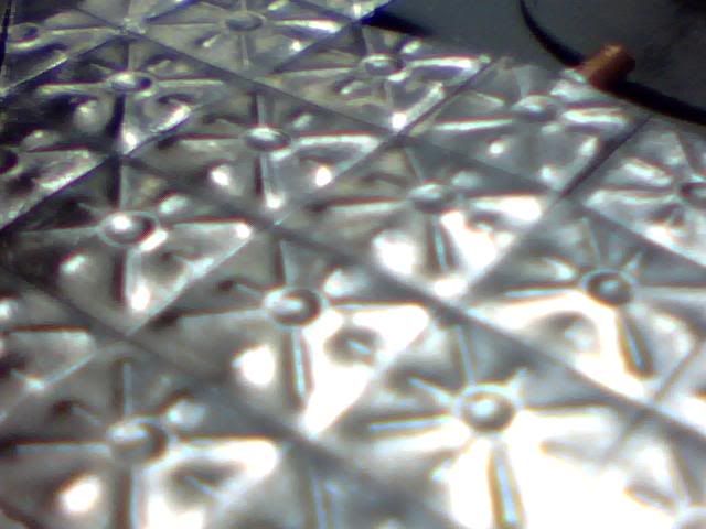
Finally a parting word on fuel tanks. I'm thinking I could make some really nice looking ones from real lead which I've used rather successfully lately for a wierd looking floor. It has the perfect colour and texture for an unpainted fueltank and it's easy to mark with grooves (as fueltanks so typically have) or anything else. Here's a shot of my last experiment with the stuff and this is on a 1:100 scale! Again forgive the poor quality...
I'm not going to dive into any further detail work until I have the turret finished and at least have some feedback so please let me know what you think as everything is easily changed at this point but it soon won't be!