Scratchbuilding C&Cs Mammoth Tank

Up to the end of WWII.
User avatar
Munty
Private
Posts: 90
Joined: Thu Mar 24, 2011 4:35 pm

Re: Scratchbuilding C&Cs Mammoth Tank

Post by Munty »

Update time, though I've been lazy/busy last few days so have only got round to a few tiny jobs today. The grill arrived yesterday from Christian (Chris3 here at the forums) and I couldn't be happier with it, he's done a great job. I asked for it to be oversized by 1mm all round but wish I hadn't as it took a lot of very nervous filing and sanding to get a snug fit on the rear of the hull. I remade one of the small triangular pieces actually as it was too short on one side for a perfect fit.

Anyway, I finally got a good fit with that so it's another job done, if a small one. I've also attached the 2 rear sections of track armour as I see no reason to have them separate from the main body. I'm going to get some short countersunk bolts and also run these from the outside in for some more security here as currently it's only glue and that's asking for trouble!

With that done I mock fitted the rear grill and the top engine cover to get an idea of how the back will look so there are a few pics of the final rear profile today as well which is a nice milestone! The turret is still missing of course but I've laid the base in position for one snap.

The 2 front tracks just need some easy bits making before they're ready to fit to the hull as well so that'll be a real landmark day! I now have just 2 more pieces to cut for the top of the hull as well so realistically I can do everything but the turret in a single sitting with a bit of determination!

The turret actually locates just forward of the top piece in these images so there will shortly be some material taken from that piece to accommodate the ring gear. The rear of the turret sits flush on the hull while the forward part is suspended somewhat. Future images will illustrate it better so I'll just let you wait for them! Here's what she looks like now...

Here's the new grill fitted in position with the big grenade sized holes.
Image
Image
And here it is fitted with my metal mesh behind it. I haven't decided how to actually mount them to each other but they'll probably be clamped on with more plastic...
Image

Here's a shot of the back of the tank as is with the turret base in its final position. Without the mesh fitted you can see just how serious an Achilles heel that grill is!
Image
And here it is without the turret showing where I'm still missing 2 pieces of the hull top. The rear most piece, visible here, will be fastened in place permanently. The 2 yet to be cut will be removable for access to the internal hardware and such.
Image
User avatar
Von kraftwerk
Lance Corporal
Posts: 217
Joined: Thu Mar 24, 2011 11:54 am
Location: London England

Re: Scratchbuilding C&Cs Mammoth Tank

Post by Von kraftwerk »

grills look neat,backing mesh perfect solution any real design would have done that I'd say,between you and blimp the running gear is getting there!
User avatar
Munty
Private
Posts: 90
Joined: Thu Mar 24, 2011 4:35 pm

Re: Scratchbuilding C&Cs Mammoth Tank

Post by Munty »

Ok, I was going to wait another week to post just so it was a nice round month of absence but hey I got impatient so here I am again!

I've been a very bad boy and done absolutely nothing on this for way too long but I've been slowly getting back into the swing of the things this week so now I have an update AND a question to pose. I need some advice on something that I'm hoping a few members here will be familiar with but that can wait till later.

For now here are some pics I've literally just taken of what I've done this week. First job was to finish off the last 4 small pieces so I could finally get the tracks all fixed onto the main hull assembly which I actually took 2 whole days to do! Seriously, it's been so long since I put it down I found it hard to pick up again, finishing just one track per day! On the third day I fixed both finished assemblies to the hull and though they look ok there is some mild misalignment in a few places so it's not dead straight as I'd hoped. That said, it's not bad enough that I'm particularly bothered by it and it really does take a really close inspection to uncover the flaws. Chances are, when it's a finished vehicle with all the detail and hardware in place it'll be impossible to tell so I've left it as is...

So between that first job and today's big finish I've continued the hunt for an engine kit with similarly appauling results as before. Finally I've found the right one though thanks to a post on these very forums that I turned up with a little help from my friend google. As I said, I want some advice and it's this engine that it's regarding but again that can wait. The reason I mention it now is because I didn't want to come here with a question and no progress so I made a final push today to cut out all the side pieces for the turret.

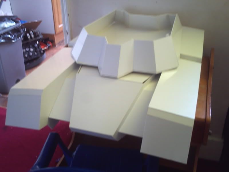
There are 14 of them in all but most are quite small so it wasn't too bad and I got all of them done in a few hours while streaming some Dragonball on the net! I've reached my limit for today so I'm going to delay assembly of these pieces until a later date but I wanted to end up with an impression of how the turret will end up looking so I've taped it together for now as a temporary representation of the end product.

Everything fitted together pretty well (I haven't cut any of the chamfers yet though so it's very crude) but the longest side panels were a serious exception. They have different angles at the front and back and on my attempting to fit them they seem to be miles off. I won't know quite what the problem is until the other pieces are fitted more permanently but there's certainly something fishy going on which you can probably tell from these pictures.

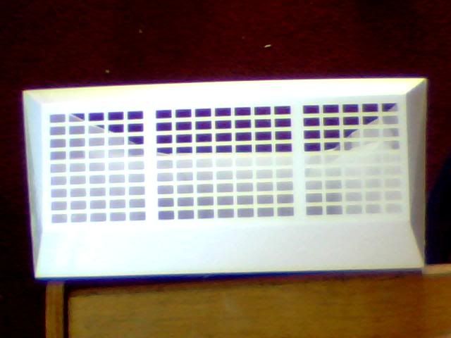
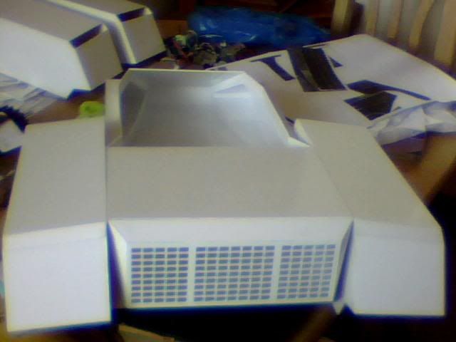
Anyway, it's only temporary and it'll at least do for now so here are some pics! The small gap visible on top of the hull is a result of me using the undersized piece to temporarily fill the gap for these images so it's not a concern. The rear piece of the hull top and the grill are also still temporarily fitted so any ugliness there won't be present further down the line.

Here she is from the front left quarter, looking much more like she should do which is always a good thing!
Image
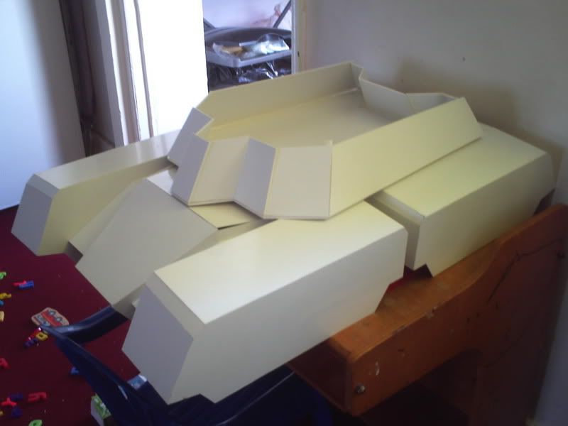
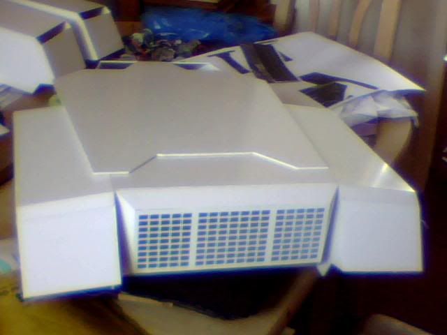
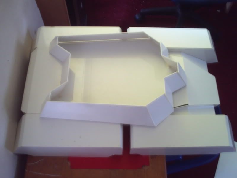
Pretty much straight on showing the lines of the turret. The two flattest areas are where the 400mm (long) cannons will be mounted!
Image
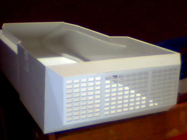
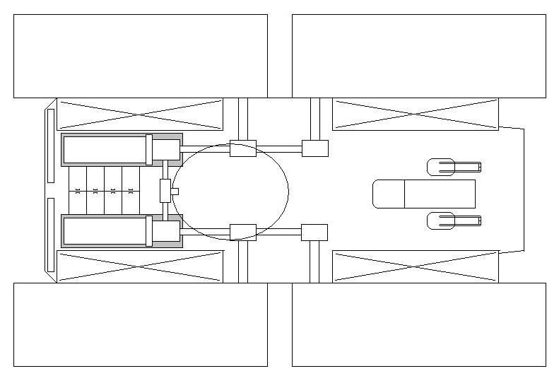
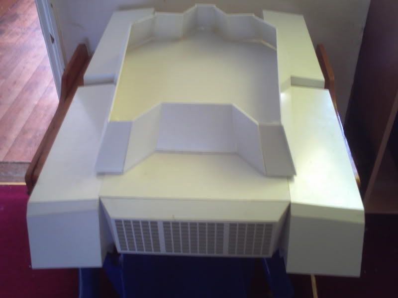
A view from above shows that there aren't many pieces missing to complete the basic shape.
Image
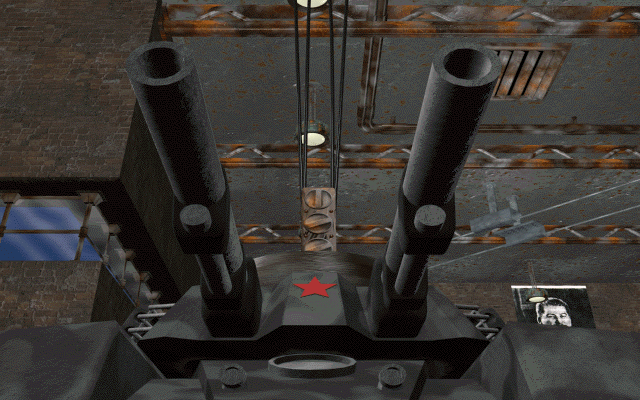
And one from behind shows a view noone will ever see. My Mammoth retreating :D
Image

That's all for now though, so onto my query...

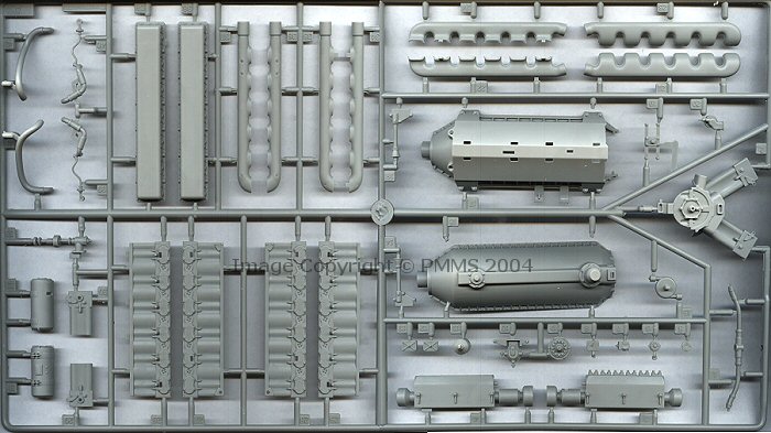
As I said I think I've finally found a suitable engine but I'm not sure if I can use it due to cost. I'm hoping some people here are familair with it so I can get a few questions answered but first, here is the kit.
Image

It's the super detailed 1/16 Trumpeter kit of the T-34, though 2 almost identical kits exist and either will do fine as both include the engine I want to use. Speaking of which...
Image
Image

There she is!

I can't be sure of how big it is but bearing in mind it's the right scale I can just work the rest of the build around the model if I can just get my hands on one!

Sadly, with the average purchase price of these things lurking around the £100 mark and the fact that I don't actually WANT 90% of the kit, I just can't justify buying it for just the engine, especially since I need two of them!!!

So here's my thought. Would it be possible to mould copies of the engine sprue and any other nifty details I could use? This is the engine one and it's really the most important one for me.
Image

I'm thinking that I could buy the kit new to ensure it's in the best possible condition (all on sprues and such) and then get some copies of the bits I need made. Then rather than ruin the kit by leaving it incomplete I could re-sell it onto a fellow enthusiast (preferably here) with all the pieces still in mint condition. I'd be able to do so for a significantly lower price than anyone else as I'd have benefitted greatly from the kit already and I figure I'm stepping on any toes by trying to clone kits or whathaveyou.

The big questions however are is it possible for me to duplicate these parts accurately? I've never done it before so really I'd be hoping to find someone to do the moulding and casting for me but either way the plan falls short if for some reason it's not possible.

I'm going to leave it with you guys and hope someone can help me out but please give me your thoughts as I LOVE this engine. It's been just impossible to find anything half good after months of searching and suddenly I found myself staring right at this thing! Of course I could always sell on the kit with just the engine missing and it could be built with the top hatches shut or whatever but it's still a compromise for a very detail rich kit so I don't see that as a very viable option (plus I'd still need 2 anyway!!!)

Let me know what you think if you read this and cheers for looking. Will post another update either following a brainstorm on the engines or when I have the hull fully assembled. I won't put the very top on for a while as it needs some hardware first but I can at least do the sides and there's anotehr layer of angled plates before the final piece is fitted anyway! See you next time, will be sooner than 3 weeks I hope!
sassgrunt
Staff Sergeant
Posts: 750
Joined: Wed Oct 29, 2008 9:08 am
Location: Hawaii, USA

Re: Scratchbuilding C&Cs Mammoth Tank

Post by sassgrunt »

Hey Tim;

As it happens, I have used two of these kits for wheels, upper hulls, and other detail parts. I still have the remainding pieces, and the engine parts are all still on the sprues. They're yours if you want them. -Mike
User avatar
Munty
Private
Posts: 90
Joined: Thu Mar 24, 2011 4:35 pm

Re: Scratchbuilding C&Cs Mammoth Tank

Post by Munty »

You're kidding! Please don't toy with me here, that would be absolutely incredible but I don't think my heart can take the shock of it as a cruel joke :D Honestly if you have them I'd be absolutely indebted to you forever if you can help me out, I'm curious as to dimensions though so I wonder if you could tell me how big the engine is? It won't be too easy if they're still on the sprues but a rough estimate would be fine as I want to start planning the 'engine room' with fuel tanks, engines and other auxiliaries. Would be a lot easier if I know how big these things will be ;) Anyway thanks a lot for the response, I'll sleep amazingly well today with that to go to bed on! T
sassgrunt
Staff Sergeant
Posts: 750
Joined: Wed Oct 29, 2008 9:08 am
Location: Hawaii, USA

Re: Scratchbuilding C&Cs Mammoth Tank

Post by sassgrunt »

I think that's how a lot of this hobby goes - like the saying "One man's trash is another man's treasure." We ALL save unused parts from kits & builds; but now with message boards like this, we can correspond with others who might have a need of them.
Trying to guesstimate by measuring the parts on the sprues and looking at the way they're assembled in your pictures, it looks like the completed engine is about 10cm long by 4cm wide by 6cm high (as it sits on the mounting frames). The pictures you showed are of the engine itself; but do not show the transmission unit that is on another sprue, (which you're welcome to also). That would add around another 4cm in length and is about 6cm wide when assembled. -Mike
User avatar
Munty
Private
Posts: 90
Joined: Thu Mar 24, 2011 4:35 pm

Re: Scratchbuilding C&Cs Mammoth Tank

Post by Munty »

Perfect, thanks for the additional info Mike (couldn't find it anywhere online! I'd guessed at roughly those dimensions so that sounds fine. I was hoping to use a larger area for the engine room but with the units only 1ocm long and the ideal size of the room being just shy of twice that I think I'll need to adjust it somewhat! The gearboxes are fantastic looking pieces of kit but sadly I don't think I can really make use of them as they would be located much further inside the tank than the kit represents them (the rear drive wheel being about 15cm forward of my rear grill)

I'm trying to think how to detail the room to flesh it out with more than just the engines now as of course it doesn't matter how detailed they are if I just stick them in a big empty box! I figure I can panel the walls with some modelling card/thin plasticard and use some pinheads or similar for rivets. That'll break up one large area. The floor can either have a fine grill or some chequerplate on it (depends what I use elsewhere on the model as there is an area of chequerplate on the reference pictures I'm using just above the engine but it seems to me that it's right where the intakes should be so I may use grill instead)

I'm currently pondering where the batteries could be stored as I'll certainly be needing a lot of them for a vehicle this size but can't think where to locate them. I wondered about having 2 rows of large ones between the two engines and then having the engineers crawlspace be a removal piece of grill to both provide access for maintenance and also to show a little more detail.

Other than that I know the kit comes with radiators which are mounted either side of the engine but for me I absolutely wouldn't want to conceal any of the detail on the inner sides of the units so I could maybe use one set for both engines but I don't know if that would be a useable configuration as there would be no airflow in that setup... Of course the rads could be placed behind the engines and directly inside the grill which would make most sense but of course then all the detail becomes invisible!

Perhaps a solution would be to make the top chequerplate pieces of the design be grills (like the slat-kind found on many tanks) and they can provide an intake and ventilation for the poor old engineer! That way I could make it so the grills can open to reveal the detail and then it wouldn't suffer from having the rads logically placed just inside the grill at the rear (I mean honestly, why else would that big weakness be present in the vehicle if it didn't serve a purpose?) Exhaust can vent anywhere I want it to really, back, top, track, side, even the bottom for all it matters. The kit comes with some nice intake parts as well so maybe that could be incorporated into this room as well?

Last thing I'd be needing is fuel tanks which could quite easily be present in the same area too. In fact it might make sense to have the rear end of two flank mounted fuel tanks visible in this room. They could carry on into the front of the tank to show how large they are but due to placement of the access to the turret it still wouldn't be possible to see forward to where the hardware will be located. That might work... Of course that would make the area I have to fill significantly larger and by comparison the engines would seem a lot smaller but hey, maybe the gearboxes could be used in such a situation? Actually, now I come to think about it, I wanted to represent a differential unit between the two sides of the drivetrain as well for situations where one engine fails while in battle.

Hmm still got a lot to think about but yes please, big style dibs on your engine bits :p We'll sort something out over pm but please take something for whatever you send me as I would've had to shell out a small fortune for these if you hadn't been able to come to my rescue! I'm going to draw up some floor plans lol

EDIT : first problem solved, engines will be dropped out with a section of floor for maintenance. Most tanks allow access from the top/rear or a combination of the two but what with my nice grill and the gigantic turret, neither really works. So instead it'll be removed from below along with 1/3 of the engine room floor! My guess is that a seperate armour plate will cover the entire underside of said area and will need removing prior to any hardware removal. Otherwise I can see this method being a bit of a liability...
User avatar
Munty
Private
Posts: 90
Joined: Thu Mar 24, 2011 4:35 pm

Re: Scratchbuilding C&Cs Mammoth Tank

Post by Munty »

Been doing some doodling lately and I think I've settled on a configuration that makes sense now! It's a bit of a mess of differentials and such but I think it makes sense. Forgive the basic image and the large space in the centre but that's where the turret basket will be so I'm guessing the majority of it will be used for ammo storage...

There is one problem with my designs to date but I think I don't really care about that anymore as I can't work with it. It stems from an unofficial wiki regarding the series of games where the tank originates so I don't care about that either way but there's also an in-game cinematic on which the wiki fact is based and this of course is official as can be.

Anyway the issue is caused by a short video showing installation of the turret to the body of one of these tanks and it's got a very odd configuration to say the least. It shows a flat bottomed turret with no basket at all but it does show a circular hole in the base which is almost completely occupied by a massive gear. That makes it impossible for any personnel to operate in the turret and also prohibits movement between there and the hull. Given that there are no other access hatches on the hull (in fact there aren't really any visible hatches anywhere in the games but the commanders cupola is going to provide my turret access and there's a possible second for the driver)

Obviously this configuration suggests that turret rotation is controlled by an external gear in the hull operating on the large internal gear of the turret. It's stupid though and it wouldn't even work at a stretch as the video shows a gear in the turret about 2 meters wide with only 12 odd teeth! That means the driven gear in the hull would have to be the same size to move it and it's just clearly nonsense. Below is the only still I have but it's too late to show the gear. The poor quality video is here for anyone really curious! http://www.youtube.com/watch?v=wQYr61epsec
Image

Anyway, that gear and the strange screwthread protruding from the bottom of it are the only bits of Command & Conquer lore that I'm going to discount from the build. Everything else I know is being adhered to as much as possible, so that in mind here's my attempt at a basic floorplan (remember most of this won't actually exist as it'll be hardware and such!
Image

The rear of the vehicle is on the left and the cockpit is in the front of the hull, on the right of this image. It's a reclined chair with a lever on each side. These control how much power is delivered to each of the four tracks and there are actually two levers on each side but they're operated in pairs. If for some reason a track is lost or some form of drivetrain issue crops up then the levers can divide to allow individual control of each track. Consider it an emergency precaution!

In the four corners of the hull are the fuel tanks, represented by rectangles marked with Xs. The gaps in the centre make space for the driveshafts which reach the 4 central sprockets to provide power to the tracks. There is a transfer box relating to each drive sprocket which can be disengaged by the driver to control which tracks are powered or again in the event of a mechanical failure or emergency. Each side of the drivetrain has it's own dedicated 12 cylinder diesel engine and the gearbox is fitted to the rear of the powerplant and delivering power depending on the drivers manipulation of various transfer boxes...

A final differential is fitted between the two sides of the drivetrain, immediately after the gearbox, it's purpose being to allow a single engine to drive the entire vehicle. This can be done by running all four tracks with a significant loss in power or more likely by running just two tracks until repairs can be made.

To try and explain the actual image a little more (as I foolishly decided not to label it!) here's a rundown from left to right...
The radiators are fitted just inside the rear grill (long narrow rectangles)
The grey areas are where the floor is open with the remaining area laid to a mesh flooring. Inside these areas are the engines, flywheels and gearboxes.
Between the two engines on the left are 8 battery compartments storing however many batteries will fit! I haven't figured that out yet...
Right of this is the central differential which I figure may also be a good place to take off power for rotating the turret. Is that usually done mechanically or with an electrical motor?
Further right are the two pairs of transfer boxes for the 4 drive sprockets and then the cockpit all the way right.

I hope that explains my grand plan for how this thing looks and works. I'm trying to find something suitable to make the flooring from right now and also looking for batteries but think I may have to make my own... That's it for now anyway, just wanted to share my ramblings as it gets awful crowded in this head of mine! Enjoy!
sassgrunt
Staff Sergeant
Posts: 750
Joined: Wed Oct 29, 2008 9:08 am
Location: Hawaii, USA

Re: Scratchbuilding C&Cs Mammoth Tank

Post by sassgrunt »

"The check," as they say, "is in the mail." I sent off the package of the engine parts to you this morning. I also sent the sprues having the transmission parts, since they have a lot of mechanical details that you might be able to use - fans & housings and stuff like that. I'll send a PM witht he details. -Mike
User avatar
Munty
Private
Posts: 90
Joined: Thu Mar 24, 2011 4:35 pm

Re: Scratchbuilding C&Cs Mammoth Tank

Post by Munty »

Thankyou man I love you!
Post Reply

Return to “Other”