So, after a long summer hiatus, it’s time to get back down to work. The flat, brass gearboxes (5:1 ratio) will fit on the standard HL posts. However, the two parallel gears nearest the final drive gear stick too far up to allow the gearboxes to be raised. If you raise the gearboxes, those gears rub on the upper hull. So, I figured that I’d try the new Mato gearboxes with the steel gears and ball bearings. I also figured that if the mounting plate fit in the PzIV, then I might have an easier way of lining everything up.
I ordered the gearbox set from eBay. They were a little cheaper than buying from Mato, but shipping took a lot longer since they were coming from China. I took them out of the box to inspect them and noticed a few things.
- They appear to be pretty solid and the gears seem to be decent steel.
- The gears do rotate independently on the shafts and the shafts can also rotate in their bearings.
- The ends of the motors that come with the gearboxes are knurled, making it more difficult to remove the pinions. (Note: on the up-side, the knurling should give the set screw a better surface to grip and hold the pinion firmly on the motor shaft.)
- The gears seem to bind some, particularly the final drive shaft. I couldn’t spin the drive shaft with my hands.
So, the first thing to do was to free up the drive shaft. Once I loosened the set screws on the final drive gear and the shaft’s collar, it turned freely. I can’t really move where either of those sit on the shaft because there are holes drilled into the shaft for the set screw to sit. (Good for being solid, bad for minor placement adjustments.) So, I filed down the collars and final drive gears for both gearboxes using a large file. I trimmed down their thickness by .5 - .75-mm. Now, the spin freely.
DAK Pz IV Ausf G Build
Re: DAK Pz IV Ausf G Build
- Attachments
-
- IMG_0011 (2).jpg (93.66 KiB) Viewed 4142 times
-
Re: DAK Pz IV Ausf G Build
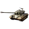
Figure looks good 
Re: DAK Pz IV Ausf G Build
Nice work Philipat, I might look into those boxes as my upper hull does not sit down properly due to the gearboxes (that and its warped!)
You can never have too many tanks...... 
Re: DAK Pz IV Ausf G Build
Thanks, I'm still playing with them. I should have a better idea of it fits together over the next couple of weeks.
The gearboxes spin much more freely now. However, there was still some binding and it looked like some of the intermediate gears might be too close together and were rubbing on each other. So, I filed down the brass spacer rods a little and inserted a couple of M3 washers to create some space between the gears.
They’re better now. But, there is still some random binding when it will be noticeably harder to spin the gears by hand-spinning the drive shaft. Or, when the gears will suddenly slow and stop after letting them spin freely. I’m not sure why that is, but I think it might have to do with rubbing on the brass spacers. I hope that goes away with some run-in.
- Attachments
-
-
HERMAN BIX

- Lieutenant-General
- Posts: 12059
- Joined: Sun Jan 12, 2014 12:15 am
- Location: Gold Coast,Australia
Re: DAK Pz IV Ausf G Build
Could be run in as you say. I test ran the steel gear sets on my Pig-Stug & they were, well, lumpy if thats a way to describe them.
I bunged some dry graphite powder on the worst one & just ran it on a stand, unloaded, & it came good after a battery load.
I just put it down to the way I mounted them, but now Im not so sure.
I bunged some dry graphite powder on the worst one & just ran it on a stand, unloaded, & it came good after a battery load.
I just put it down to the way I mounted them, but now Im not so sure.
HL JAGDPANTHER,HL TIGER 1,HL PzIII MUNITIONSCHLEPPER, HL KT OCTOPUS,HL PANTHER ZU-FUSS,HL STuG III,HL T34/85 BEDSPRING,
HL PZIV MALTA,MATORRO JAGDTIGER,HL F05 TIGER,TAMIYA KT,HL PANTHERDOZER,HL EARLY PANTHER G,TAIGEN/RAMINATOR T34/76,
HL AN-BRI-RAM SU-85
HL PZIV MALTA,MATORRO JAGDTIGER,HL F05 TIGER,TAMIYA KT,HL PANTHERDOZER,HL EARLY PANTHER G,TAIGEN/RAMINATOR T34/76,
HL AN-BRI-RAM SU-85
Re: DAK Pz IV Ausf G Build
Interesting...lumpy is a good way to describe it. It'll run smooth and then suddenly start to bind up. Next spin might be smooth or a little bound.
When you say it came good after a batter load, does that mean it was consistently smooth? No more lumpy?
Also, what do you mean by running it unloaded? Did you use the tank's electronics and battery to run the gearbox continuously until the battery ran down? (no sprocket or tracks) Or, did you run it in using a drill to turn the gears? (after removing the motor )
)
TIA
When you say it came good after a batter load, does that mean it was consistently smooth? No more lumpy?
Also, what do you mean by running it unloaded? Did you use the tank's electronics and battery to run the gearbox continuously until the battery ran down? (no sprocket or tracks) Or, did you run it in using a drill to turn the gears? (after removing the motor
TIA
-
HERMAN BIX
- Lieutenant-General
- Posts: 12059
- Joined: Sun Jan 12, 2014 12:15 am
- Location: Gold Coast,Australia
Re: DAK Pz IV Ausf G Build
Yes sir, ran it on a stand with no running gear fitted at all. Used the tanks electrics.
Also slid the trim over to the 'lumpy' side so all the juice went into it.
Seems to have calmed it down.
Also slid the trim over to the 'lumpy' side so all the juice went into it.
Seems to have calmed it down.
HL JAGDPANTHER,HL TIGER 1,HL PzIII MUNITIONSCHLEPPER, HL KT OCTOPUS,HL PANTHER ZU-FUSS,HL STuG III,HL T34/85 BEDSPRING,
HL PZIV MALTA,MATORRO JAGDTIGER,HL F05 TIGER,TAMIYA KT,HL PANTHERDOZER,HL EARLY PANTHER G,TAIGEN/RAMINATOR T34/76,
HL AN-BRI-RAM SU-85
HL PZIV MALTA,MATORRO JAGDTIGER,HL F05 TIGER,TAMIYA KT,HL PANTHERDOZER,HL EARLY PANTHER G,TAIGEN/RAMINATOR T34/76,
HL AN-BRI-RAM SU-85
Re: DAK Pz IV Ausf G Build
Cool...sounds like it just needs some run in. Thanks.
Re: DAK Pz IV Ausf G Build
One of the reasons I’m interested in the Mato gearboxes is that they come with a mounting plate, which would add some rigidity to the lower hull, particularly in the front. I originally asked Mato if this would work on the PzIV, but was told it was made for the Tiger I. I remembered someone else saying that they had used the gearboxes in their PzIV. So, I figured that I’d get it and try it out. The plate fits perfectly. It has four holes in the corners where the plate bolts to the stock gearbox mounts. There are also holes for the plastic nubs that the stock gearboxes use as alignment nubs. The gearboxes bolt into the metal plate and keep them aligned correctly.
Nice thing about the Mato gearboxes in the PzIV is the front gears (nearest the drive shaft) are low and they rise going backwards towards the motors. That allows me to raise the gearboxes without having the gears rub on the upper hull. However, it did cause the motors to bump into the 8-pin plug in the upper hull. So, I’ll have to relocate that plug. Also, the high-low motor configuration should allow me to install different motors and experiment with Speed400s, 480s, or 390s (if I can find any of those...banebots.com is out).
As far as the plate goes, it fits perfectly. It also adds about 1.5-mm to the sprockets’ height. So, I can use a couple of .75-mm M3 washers to bring it up a total of 3-mm without rubbing the gears on the upper hull or the tracks on the upper hull. However, it seems that the sprockets stick out about 2-mm too far. To make the tracks line up with the sprockets I’ve used 2-mm aluminum spacers on the suspension and 1-mm aluminum spacers on the return rollers. I’ve test run it a couple of times without the upper hull and everything works well. Adding the upper hull results in some rubbing from the edge of the tracks against the small lip on the edge of the fenders. The tracks barely clear the inside of the mud flaps, but they’re doing okay. I’ll have to look into shortening the drive shafts by 1 or 2 mm. Can’t be too much because the outer edge of the tracks was just inside the fender lip on the real tank.
Note: if you’re using Taigen or HL tracks you may not rub against the lip of the fenders. I’m using Impact tracks that have a small knob at the outer edge of each track link that simulates the link nuts.
Re: DAK Pz IV Ausf G Build
So, I’m still working on the lower hull, particularly the drive gear (gearboxes, transmission covers, motors, etc). Right now, milliput is hardening and JB Weld is curing. So, in the meantime, I rebuilt one of the antenna tray brackets that broke off somewhere along the way. The first time I built it, I glued everything to the surface. This time, I drilled into the plastic to embed everything. Work done:
- 2-mm hole drilled for the bolt mount at the top of the bracket.
-The bolt mount was made using 2-mm styrene rod with a .8-mm hole drilled for the bolt. I sank the styrene rod into the hull side by 2-3 mm.
- .8-mm hole drilled for the bottom bracket’s bolt.
- bracket was made using F-1x-3 brass strip from http://www.specialshapes.com.
- all epoxied in place using JB Weld.
Suggested work order:
- Shape the primary bracket and cut and drill the styrene rod.
- Use the primary bracket to line up the hole for the bolt into the hull for the support bracket. Drill that hole.
- Make the support bracket (do not cut to length yet).
- Drill a .8-mm hole in the bottom of the main bracket (bottom = where the bottom of the antenna tray rests in the bracket).
- Line up the support bracket it under it and use the hole as a guide to drill a .8-mm hole in the support bracket. Cut the support bracket to length.
- Glue/epoxy the support bracket to the main bracket. Insert a .8-mm hex head bolt through the hole. Let epoxy harden.
- Cut the protruding bolt so that the antenna tray sits flat in the bracket (basic Tamiya side snips will do it).
- Epoxy the assembly (styrene rod in hull, main bracket to rod, support bracket to hull) to the hull as a single unit. Use .8-mm bolts in the support bracket (to the hull) and the main bracket (into the styrene rod). Use the antenna tray to fine tune the bracket placement.
Hopefully, this way it will last longer than my last effort.
- 2-mm hole drilled for the bolt mount at the top of the bracket.
-The bolt mount was made using 2-mm styrene rod with a .8-mm hole drilled for the bolt. I sank the styrene rod into the hull side by 2-3 mm.
- .8-mm hole drilled for the bottom bracket’s bolt.
- bracket was made using F-1x-3 brass strip from http://www.specialshapes.com.
- all epoxied in place using JB Weld.
Suggested work order:
- Shape the primary bracket and cut and drill the styrene rod.
- Use the primary bracket to line up the hole for the bolt into the hull for the support bracket. Drill that hole.
- Make the support bracket (do not cut to length yet).
- Drill a .8-mm hole in the bottom of the main bracket (bottom = where the bottom of the antenna tray rests in the bracket).
- Line up the support bracket it under it and use the hole as a guide to drill a .8-mm hole in the support bracket. Cut the support bracket to length.
- IMG_0026-1.jpg (91.8 KiB) Viewed 4049 times
- Epoxy the assembly (styrene rod in hull, main bracket to rod, support bracket to hull) to the hull as a single unit. Use .8-mm bolts in the support bracket (to the hull) and the main bracket (into the styrene rod). Use the antenna tray to fine tune the bracket placement.
Hopefully, this way it will last longer than my last effort.
- Attachments
-
-
- IMG_0029 (2).jpg (97.62 KiB) Viewed 4049 times
-
- IMG_0028.jpg (94.27 KiB) Viewed 4049 times
-
- IMG_0027-1.jpg (95.14 KiB) Viewed 4049 times
