The external bits of the Cromwell are now fairly complete, apart from a few hinges, grab handles, and other minor details. Recent days have disabused of the idea that scratch building is straightforward. This simplistic take:- ....Plans; styrene; cutting implements and glue- what could be simpler, for a lazy afternoon's diversion, eh? ...Hmmmph.
For starters, if you've been assembling tanks with parts from HL, Taigen, Mato, and Tamiya much of the work is done for you. You have moulded plastic standoffs, for example, and they help you assemble components in the right place, at the right height. Not so with flatpack styrene tanks.

Standoffs for the rotation motor, 8-pin connector etc all have to be fabricated....and, it's not as easy as you might think. Component locations are critical, as are factors like height, clearance and more. In short; you have to start measuring things, and making calculations

That's right: it's back to school for scratch building apprentices!
Problems to tackle, just to install the turret ring and motor.
1. The gap between a standard HL/Taigen turret ring and the Cromwell's turret aperture is too big; so that the turret can slide around, and collide around..

2. All HL Taigen tanks have a 5mm (or so depending on model) moulded plastic flange/spacer between the upper hull deck and the turret ring. This means the top surface of the ring is 10mm above the deck.
Sitting in the same position, the Cromwell only offers 5mm height, as there is no moulded flange, just flat styrene

I need an extra 5mm minimum from somewhere..
3. Standard HL/Taigen 10cm ring won't fit easily in the Cromwell's confined front upper hull section. The tab to prevent 360 deg rotation actually prevents the turret from turning, and had to GO..
4. Nothing to attach turret motor to. Normally it sits on moulded plastic standoffs giving it a clearance of some 5mm (for cables, resistor etc..). The Cromwell kit has no standoffs. Not one.
First, I had to cut out a section from the central bulkhead in the upper hull to accommodate the driven wheel of the turret motor. The motor wouldn't fit anywhere else. Then it needed 5mm standoffs, which I then made.
This gave it the required height of 2cm above the deck. I tried it the other way up, and other orientations, but this was the
only solution I could find. Don't know how the (Ist) builder of Tom's tank did it..
Then I had to convert the (black) turret ring for 360 rotation, by cutting two new teeth. (haven't cut teeth for many, many decades

). Then I had to cut the ring off the other turret ring, and trim 2mm of the ring flange to. By careful measurement, I found that if I bonded the doctored amber ring to the black one, I'd have the height I needed to make the turret ring and turret motor gears mesh properly. With not alteration, the mesh
(non-mesh) was 5mm out...
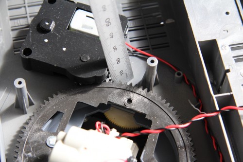
- Getting correct dimensions from a Pz IV turret
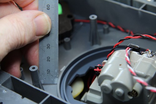
- Built in 5mm flange- missing from Cromwell
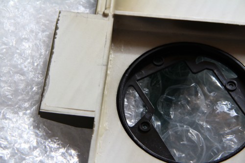
- Gap too large between Turret ring and Cromwell Hull
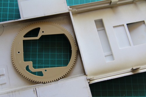
- Ring won't fit in Cromwell forward hull..
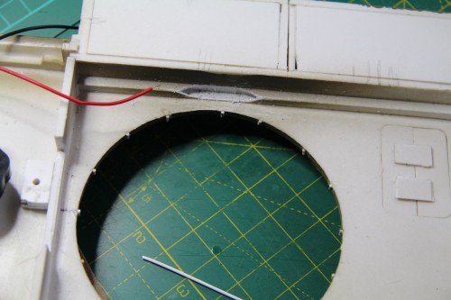
- Turret rings 1.5 mm bearings fitted to bridge gap
To reduce the gap that left the turret sloshing around on the hull, I etched some fine lines in the turret aperture, and created little 'bearings' from 1.5mm styrene. These work well, and create a tighter fit.!
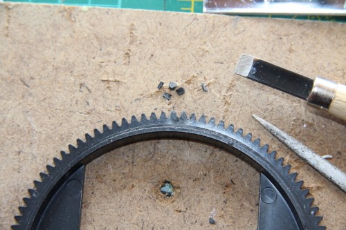
- Making black ring 360 degree type..two new teeth
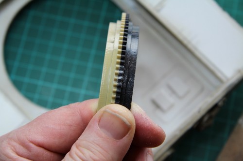
- Two new teeth compared with those on other ring
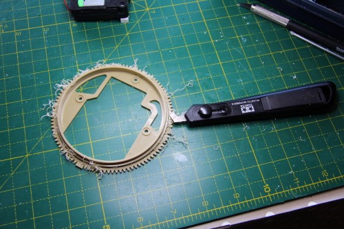
- Trimming rim off one wheel to make flange for other
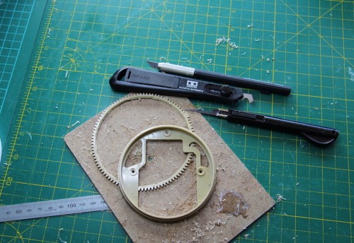
- Extracting some teeth..
Then after careful height measurements, I bonded the two Turret rings into a new taller one. Fingers crossed..this is all unknown territory for me..
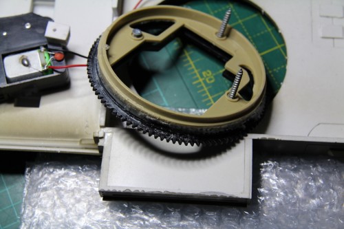
- Two tone turret ring...
Back in a minute..