1/16 RC US 155mm Gun Motor Carriage M12 - Build

Re: 1/16 RC US 155mm Gun Motor Carriage M12 - Build
Chiming in re Vandra kits. My building focus is for functioning models to be used in IR battles, not for finescale detail. I find them a fun challenge. They're certainly not "shake the box and it's done" products.
Renault FT, British WW1 Mk. 4), Pz 1A DAK, 1B, II L, III, StuG III, PzKpfw IV, StuG IV, King Tiger, T-34/76, KV-1E, T-35A 3DP, Zik-2, T-90, M3 Lee, M4 Sherman, M26 Pershing, M41 Bulldog, M1 Abrams. In the works: Ram II, Pz 1 Breda. 

Re: 1/16 RC US 155mm Gun Motor Carriage M12 - Build
I'm sure if anyone can fix the M12, lmcq11 can...  My Vandra SU-122 has been shelved for a while so I can forget how frustrating fixing the gun elevation is.
Derek
Too many project builds to list...
Too many project builds to list...
-
EAO

- Warrant Officer 2nd Class
- Posts: 1162
- Joined: Sun May 10, 2020 5:29 pm
- Location: Central Missouri, U.S. of A.
Re: 1/16 RC US 155mm Gun Motor Carriage M12 - Build
Louis,
Now this will be fun...again!
Can you imagine being around one of these when it sent a round downrange?!? That blast must have been brutal!
As the late Col. Jeff Cooper once said, "If I had known that I'd live through all these battles, I might have worried about hearing protection"!
Cheers,
Eric.
Now this will be fun...again!
Can you imagine being around one of these when it sent a round downrange?!? That blast must have been brutal!
As the late Col. Jeff Cooper once said, "If I had known that I'd live through all these battles, I might have worried about hearing protection"!
Cheers,
Eric.
"You can always tell a German, you just can't tell him much." Anonymous.
German cars, German girls, German beer, German firearms, German Shepherds, German motorcycles... Not necessarily in that order though!
UP THE IRONS!
German cars, German girls, German beer, German firearms, German Shepherds, German motorcycles... Not necessarily in that order though!
UP THE IRONS!

Re: 1/16 RC US 155mm Gun Motor Carriage M12 - Build
Thank you guys for your encouragements, i think this is becoming a difficult build.
This post is for the suspension bogies.
To make the build more interesting, i decided to introduce a component i never used before, the Sherman Mato metal bogies that comes with the all metal Sherman and M10. The original M4A1 plastic bogies were way oversized, positioned too far away from the hull and not enough space was left between bogies for the suspension to fully operate. Comparing them with the metal replacement, it is an improvement but we can see how oversized the plastic bogies where, and probably how undersized the metal replacements are.
The suspension on these is fabulous. It operates like the real thing. No more simple swivel and no compromises.
The suspension arms elevates independently and they slides under the arm above, linked to a pivot central part with two real compression springs which swivel inside the suspension hub, and sliding up and down along rails as well.
It is the first time i investigate these bogies, a nice touch over the use of plastic Mato or Heng Long bogies.
They need some clean up, a bit of polishing and filing of the rubber band to make them look worn without the molding edges. Comparing before and after.
For some reason that eludes me, Mato wants its suspension to be 3mm away from the hull than it should. I see no reason for that. The spacers that were doing that were removed with the Dremel and a sanding disk. Not easy as it is quite hard.
The metal bogies are ready to be mounted on the hull.
They were attached using epoxy glue as the metal attachment that locked the bogies inside the hull were not usable anymore due to the removal of the spacers on the front plate.
The interior of the hull was cleaned up of all features, and made ready for the next steps. This is where the bad surprised started.
Continuing on following post
This post is for the suspension bogies.
To make the build more interesting, i decided to introduce a component i never used before, the Sherman Mato metal bogies that comes with the all metal Sherman and M10. The original M4A1 plastic bogies were way oversized, positioned too far away from the hull and not enough space was left between bogies for the suspension to fully operate. Comparing them with the metal replacement, it is an improvement but we can see how oversized the plastic bogies where, and probably how undersized the metal replacements are.
- 1/16 RC US 155mm Gun Motor Carriage M12 - Build
- 1/16 RC US 155mm Gun Motor Carriage M12 - Build
- 1/16 RC US 155mm Gun Motor Carriage M12 - Build
- 1/16 RC US 155mm Gun Motor Carriage M12 - Build
- 1/16 RC US 155mm Gun Motor Carriage M12 - Build
- 1/16 RC US 155mm Gun Motor Carriage M12 - Build
- 1/16 RC US 155mm Gun Motor Carriage M12 - Build
- 1/16 RC US 155mm Gun Motor Carriage M12 - Build
- 1/16 RC US 155mm Gun Motor Carriage M12 - Build
- 1/16 RC US 155mm Gun Motor Carriage M12 - Build
Re: 1/16 RC US 155mm Gun Motor Carriage M12 - Build
The 1/35 scale Academy kit will get partially assembled as i advance with the 1/16 model, and will be kept at my side at all times.
Bad surprise, by dry fitting the deck over the lower hull, we can see that the Vandra M12 designer did not represent the upper hull correctly. The deck is not lowered inside the hull as it should be. And that also means that a lot of other things will also not be right.
Double checking with reference book also show the deck is about 1 feet lower than the Vandra kit.
Ok... no trouble, i hated the double diamond tread plates anyway. Cracking the hull open on a Vandra kit is unavoidable when looking for an accurate model. But i was not planning having to do this, there is nothing easy with these kits. I really want an M12 that is accurate, not something that looks like an M12 twelve feet away. These kits are not for everyone, and it might be easier to just scratch build one...
Ah, another bad surprise. Despite my calculations and the shaving of some of the metal from the Sherman gearbox, i am missing about 2mm for the upper hull to fit over the motor at the top. Need to find a solution.
Time for a break and some re-planning.
Regards, Louis
- 1/16 RC US 155mm Gun Motor Carriage M12 - Build
- 1/16 RC US 155mm Gun Motor Carriage M12 - Build
- 1/16 RC US 155mm Gun Motor Carriage M12 - Build
- 1/16 RC US 155mm Gun Motor Carriage M12 - Build
- 1/16 RC US 155mm Gun Motor Carriage M12 - Build
Regards, Louis
Last edited by lmcq11 on Wed Feb 09, 2022 11:05 pm, edited 1 time in total.
Re: 1/16 RC US 155mm Gun Motor Carriage M12 - Build
Louis,
Looks like the Vandra kit is made to only "appear" to be an M12.
Barry
Looks like the Vandra kit is made to only "appear" to be an M12.
Barry
"Details make perfection, and perfection is not a detail."
Leonardo Da Vinci
Leonardo Da Vinci
Re: 1/16 RC US 155mm Gun Motor Carriage M12 - Build
That's an understatement...BarryC wrote:Louis,
Looks like the Vandra kit is made to only "appear" to be an M12.
Barry
Derek
Too many project builds to list...
Too many project builds to list...
Re: 1/16 RC US 155mm Gun Motor Carriage M12 - Build
Yeah, Checking dimensions against references like a good 1/35 kit would not take the designer much effort. It would actually be simpler as it would ensure the parts come together at the end, and the accuracy would be ensured.BarryC wrote:Looks like the Vandra kit is made to only "appear" to be an M12
Continuing with the build.
Looking at the upper hull in preparation for the next step, i saw there is a strip along the hull that need to be reduced from 6mm to 4.5. Its going way too low and it shows when sitting on the lower hull.
- 1/16 RC US 155mm Gun Motor Carriage M12 - Build
- 1/16 RC US 155mm Gun Motor Carriage M12 - Build
- 1/16 RC US 155mm Gun Motor Carriage M12 - Build
- 1/16 RC US 155mm Gun Motor Carriage M12 - Build
- 1/16 RC US 155mm Gun Motor Carriage M12 - Build
- 1/16 RC US 155mm Gun Motor Carriage M12 - Build
- 1/16 RC US 155mm Gun Motor Carriage M12 - Build
- 1/16 RC US 155mm Gun Motor Carriage M12 - Build
- 1/16 RC US 155mm Gun Motor Carriage M12 - Build
- 1/16 RC US 155mm Gun Motor Carriage M12 - Build
Last edited by lmcq11 on Thu Feb 10, 2022 11:56 pm, edited 11 times in total.
Re: 1/16 RC US 155mm Gun Motor Carriage M12 - Build
Before doing anything at the rear, the upper hull at the front need to be integrated with the transmission cover. Some adjustment is required to get the best fit possible there, which will then determine by default the situation at the rear. The integration at the front looks simpler to do than it actually is... How it ends up depends on the skill of the builder. The fenders that will hide the joint line will be added later.
This is the situation at the rear, looking ok. The upper hull is probably 1 or 2 mm too long. I already pushed the upper hull as forward as possible.
Dry fitting the new lower base for the howitzer and doing some calculations and planning for next steps. The rear is vertical down to the base, and then angled towards the inside. The 1/35 kit will provide the specs because there is very limited info on the rear of the M12, the rear blade is pretty much hiding the bottom of the hull in that area, its not showing on any picture.
The new base will have sides that will connect to the upper hull so that when the upper hull is raised to access the electronics, the whole base with the howitzer will slide and come out as well, along with all the servos attached to it.
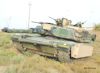
The M12 as it stands today.
Regards, Louis
- 1/16 RC US 155mm Gun Motor Carriage M12 - Build
- 1/16 RC US 155mm Gun Motor Carriage M12 - Build
- 1/16 RC US 155mm Gun Motor Carriage M12 - Build
- 1/16 RC US 155mm Gun Motor Carriage M12 - Build
- 1/16 RC US 155mm Gun Motor Carriage M12 - Build
Re: 1/16 RC US 155mm Gun Motor Carriage M12 - Build
Hi,
Building the 1/35 kit in parallel with the 1/16 model allows me to learn about the M12, of which i really did not know anything. I am discovering it as i go. Comparing the two, we can see the differences with the Vandra kit, including the deck floor previously discarded. Most structural details are simplified, or purely invented to patch an area that the designer did not want to focus on.
Sometimes, i do not bother building the 1/35 kit, i would just analyse the individual parts and instructions, and do something similar. But the level of work required for this build prompts me to completely build the 1/35. This reminds me of my 1/35 days and why i switched to 1/16 kitbashing... I would finish the 1/35 in a couple of days... Following instructions, taking care of ejection pins or using a bit of putty here and there really does not bring any challenge. But its really good to get an accurate model. I would not be able to do this 1/16 model just by looking at some pictures. I need the three dimensional view.
The left side crew seating area is hollow, with storage under the seats. The seats level are lower than the top plate. There are also triangular plates that protrude inside. The floor is lower. The ammo rounds are places on top of the deck floor, and not inside it. There are ammo stands on the sides. Engine air filters at the front. The floor thread plate is partial and of a single diamond pattern.
The right side has a hollow storage compartment. Check out the modified Sherman idler adjusters.
A new rear plate is done in 3mm plasticard, and reinforced inside. The dimensions and angle of the new rear plate are taken from the 1/35 kit.
The Mato metal Sherman Idler adjusters need modifications. The first step is the remove the rear panels for the bolts with a metal saw, and do some filing.
The mounts for the rear blade is right on top of the idler adjusters, and there is a notch inside them where the brackets for the blade go into.
These are the finished mounting for the idler adjusters. The ears that are bolted on the sides are not exactly as they should be but since these are mostly hidden behind the idler wheels and tracks, i did not bother modifying them.
The rear of the vehicle is cut. I removed about 4mm in length from the Vandra upper hull at the back. This makes it more in line with measurements of the 1/35 kit and aligns with the fighting compartment deck. The bottom rear plate is prepared to have the idler adjusters installed.
As most of the rear plates with bolts had to be removed, the idler adjusters are glued with epoxy, and also bolted on the sides.
continuing on following post
Building the 1/35 kit in parallel with the 1/16 model allows me to learn about the M12, of which i really did not know anything. I am discovering it as i go. Comparing the two, we can see the differences with the Vandra kit, including the deck floor previously discarded. Most structural details are simplified, or purely invented to patch an area that the designer did not want to focus on.
- 1/16 RC US 155mm Gun Motor Carriage M12 - Build
- 1/16 RC US 155mm Gun Motor Carriage M12 - Build
- 1/16 RC US 155mm Gun Motor Carriage M12 - Build
- 1/16 RC US 155mm Gun Motor Carriage M12 - Build
- 1/16 RC US 155mm Gun Motor Carriage M12 - Build
- 1/16 RC US 155mm Gun Motor Carriage M12 - Build
- 1/16 RC US 155mm Gun Motor Carriage M12 - Build
- 1/16 RC US 155mm Gun Motor Carriage M12 - Build
- 1/16 RC US 155mm Gun Motor Carriage M12 - Build
- 1/16 RC US 155mm Gun Motor Carriage M12 - Build
Last edited by lmcq11 on Sun Feb 13, 2022 12:09 am, edited 7 times in total.
