Louis, I had to download your build so far to study it. I admire and enjoy your combination of historical education, your trip with your father, your attention to detail, and and your incredible skill. Thank you for all the effort you put into this build, and even if I am silent, I am nonetheless reading with great interest.
I hope someday to have a 1/16 RC Churchill, for even if it looks old-fashioned, it was the first British AFV about which I learned as a youngster, and for me it defined British WWII armor just as the Sherman defines US WWII armor.
RC 1/16 Churchill Mk III - Dieppe Raid 1942 - Build
-
Herr Dr. Professor
- Major
- Posts: 6101
- Joined: Mon Apr 22, 2019 10:48 pm
- Location: Southern Wisconsin USA

Re: RC 1/16 Churchill Mk III - Dieppe Raid 1942 - Build
Indeed, its difficult to find modern graphics of the Churchill.Kaczor wrote:Great project and history! It's a pity that there is no second part of GunPower Churchill book about later variants.
I've been modeling all my life since i was 5... That 34 year business career in IT was a sideline...Jimster wrote:You, sir, are a tank modeling beast. As always I’ll be following your unstoppable tank building blitzkrieg.
I have not yet decided which name i will give it. TBD later but i have my favorites; Blondie, Buttercup, Cat and CheetahEstnische wrote:It seems you have front and side pictures of 'Bert'. Are you tempted to model that Churchill?
(Sitting back with coffee to enjoy this).
Thanks, Hope it will turn out good.SEAN66 wrote:Look Forward to this Build
regards
Sean
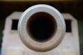
You're right, i see it now. Perfect size for the fiber i have. Thanks for the tip.Exhibitedbrute wrote:The shapeways machine guns have a small tube down the length of the piece.
Thanks, all Ludwig kits are not created equal. From what i have seen so far, this is a good one. At least the dimensions look good. And there are not too many angles to worry about. This European war site road trip i did with my father are the fondest memories i have with him. Just two guys, no women or kids, fantastic itinerary (ie Verdun, Bulge, Passchendaele, Vimy, the Somme, France coast down to Normandy... V2 sites, museums, tanks, among others). I highly recommend such trip with a family member or friend that understands and has same interest.Raminator wrote:Another great project lined up Louis, it's very interesting to see the research and personal experience behind this one. I'm excited to see what you do with Christian's kit, especially with those fantastic DKLM tracks!
Yeah, this build is special for me as well. Its time for the Churchill. I waited to be retired to start it so that i am not distracted by work. Hope to do a good job.Herr Dr. Professor wrote:I hope someday to have a 1/16 RC Churchill, for even if it looks old-fashioned, it was the first British AFV about which I learned as a youngster, and for me it defined British WWII armor just as the Sherman defines US WWII armor.
Continuing with the build
I did not know the Churchill very well. The running train pretty much hidden under the tank was a mystery. Churchill versions have different turrets, and side configurations. Enough books, i decided to invest a few hours in building the AFV Club 1/35 Mk III Dieppe kit up to the point that i needed to for now.
- RC 1/16 Churchill Mk III - Dieppe Raid 1942 - Build
- RC 1/16 Churchill Mk III - Dieppe Raid 1942 - Build
- RC 1/16 Churchill Mk III - Dieppe Raid 1942 - Build
- RC 1/16 Churchill Mk III - Dieppe Raid 1942 - Build
- RC 1/16 Churchill Mk III - Dieppe Raid 1942 - Build
- RC 1/16 Churchill Mk III - Dieppe Raid 1942 - Build
- RC 1/16 Churchill Mk III - Dieppe Raid 1942 - Build
- RC 1/16 Churchill Mk III - Dieppe Raid 1942 - Build
- RC 1/16 Churchill Mk III - Dieppe Raid 1942 - Build
- RC 1/16 Churchill Mk III - Dieppe Raid 1942 - Build
Last edited by lmcq11 on Fri Jul 23, 2021 1:28 am, edited 2 times in total.
Re: RC 1/16 Churchill Mk III - Dieppe Raid 1942 - Build
Still planning stage at this time.
I have assembled the Ludwig right side (at the back) without having glued it. This is important because this is planning to identify the modifications required to retrograde the model to a Mk III. Need to find out now, not after anything is glued. I am finding there are much differences between a Mk III and a Mk VII. As my tank will not have any track cover as well, i have identified all the section that need removal (greyed out with red pins). New parts will be to be scratch built for the sprocket and idler extensions, in addition to some other details like the rectangular hatch. The parts are flat, not many angles so this will be easy using graph and the 1/35 kit as a model.
Another area of worries were the tracks. Despite the differences in the middle section between track types for Mk III and Mk VII, I am happy to see that the width is the same and perfect. By the way, the AFV Club plastic tracks are extremely painful to assemble. I was happy to stop after my first one. Whoever wants to complete the 1/35 Mk III should get some early Churchill metal tracks from Friulmodel or other brands. You'll need them to keep your sanity.
The Churchill does not have return rollers. It was another mystery as to what supports the track under the covers. I can see now that these are rails, metal against metal. I need to order some L shaped brass strips for this.
Notice the support extension to the front. What design...
As the metal tracks are heavy, they need good support. I ordered my L shaped brass from Knupfer from Germany with tons of other brass stuff i needed. Small envelope usually make it fast. I do not have enough on inventory.
I verified that the Ludwig road wheels will work well with the DKLM tracks. I will have to adjust the space between the roadwheels on both side of each track accordingly because Ludwig designed his kit for the Sherman track and its probably not the same.
Checking the DKLM tracks on the unaltered Ludwig parts that has sides for track covers. We can see that the DKLM tracks do it fit inside the allocated space inside, meant for Sherman tracks. The elevated section on each sides for the track cover are way too thick. As I will be cutting these, there are no more issues. The width of the main section themselves without track cover are good. I might have to remove 0.5mm in width on the sides of the Ludwig parts as the parts are quite thick. Not sure yet, TBD after the parts are all cut.
With the tracks exposed like a WW1 Mk IV, this Churchill shall look good. It should be impressive to see the tracks rolling 360.
I am a rivet counter so these new parts should be accurate and fairly easy to repro. Plasticard and real metal bolt heads shall do the job very cleanly.
This is it for now. The planning stage is finished. I am happy with the dimensions i saw. Next phase; the cutting starts.
Regards, Louis
I have assembled the Ludwig right side (at the back) without having glued it. This is important because this is planning to identify the modifications required to retrograde the model to a Mk III. Need to find out now, not after anything is glued. I am finding there are much differences between a Mk III and a Mk VII. As my tank will not have any track cover as well, i have identified all the section that need removal (greyed out with red pins). New parts will be to be scratch built for the sprocket and idler extensions, in addition to some other details like the rectangular hatch. The parts are flat, not many angles so this will be easy using graph and the 1/35 kit as a model.
- RC 1/16 Churchill Mk III - Dieppe Raid 1942 - Build
- RC 1/16 Churchill Mk III - Dieppe Raid 1942 - Build
- RC 1/16 Churchill Mk III - Dieppe Raid 1942 - Build
- RC 1/16 Churchill Mk III - Dieppe Raid 1942 - Build
- RC 1/16 Churchill Mk III - Dieppe Raid 1942 - Build
- RC 1/16 Churchill Mk III - Dieppe Raid 1942 - Build
- RC 1/16 Churchill Mk III - Dieppe Raid 1942 - Build
- RC 1/16 Churchill Mk III - Dieppe Raid 1942 - Build
- RC 1/16 Churchill Mk III - Dieppe Raid 1942 - Build
Regards, Louis
Last edited by lmcq11 on Fri Jul 23, 2021 10:57 am, edited 1 time in total.
-
jee
- Warrant Officer 2nd Class
- Posts: 1023
- Joined: Thu Apr 22, 2021 4:16 am
- Location: Siberia
- Contact:
Re: RC 1/16 Churchill Mk III - Dieppe Raid 1942 - Build
very interesting, the Churchill is not my favorite tank, but has something interesting as it is different (looks different to me anyway  )
)
and also very interesting to see how you approach such a build, I will read a few more times to learn from it, and follow your progress of course.
and also very interesting to see how you approach such a build, I will read a few more times to learn from it, and follow your progress of course.
Regards,
Jaap
Jaap
Re: RC 1/16 Churchill Mk III - Dieppe Raid 1942 - Build
Thank you Jee for your encouragements !
I was in Calgary, Alberta, Canada in 2018 where i had the chance to visit the Military museam. Calgary is home of the tank regiment that landed on Dieppe. They have a Churchill Mk VII that i was able to do a walk around.
It is actually a Crocodile flame thrower.
Although the Mk VII has a very different configuration than the Mk III, the suspension and roadwheels are the same. I was able to take quite a few good close ups. We can see details of the road wheels attachments points and the armor plates above them.
The AFV Club 1//35 has reproduce the suspension very well. However, there is no such details available for the Ludwig kit.
The Churchill is a pannier design, with portions of the armoured hull extending outward of the outer edges of the tracks. The space between the upper and lower runs of the tracks allows for a rectangular panniers on each side, making it a roomy vehicle that was appreciated by the crews. It also allowed for side escape hatches, a feature that saved the lives of many crewmen escaping their vehicles.
Starting the construction of the panniers. The Ludwig parts for the Mk VII will be salvaged and reused to provide thickness and solidity to the model. Be aware that the pre-drilled location holes for the panniers are wrong. If these were used, the Churchill would be too low on its road wheels by quite a few mm. I therefore recalculate width, length, height, etc of everything on this built according to specs.
The Ludwig pannier parts are cut to the shape of the MK III. I always dislike the location holes that will be difficult to mask later, and also the round escape hatch.
In order to properly represent the Mk III, i created a new flat armour overlay consisting of two 2mm plasticard plate on top of each other and glued to the Ludwig part. This allows for the right thickness of the attachment points at the rear of the pannier for the extension for the sprocket cover, replicating the layout of the Mk III. We will see the sprocket area later and you will understand.
The Ludwig part is 5mm thick so i had to recalculate the correct width of the panniers according to specs and i reused the braces for the inside of the panniers. From the start, i pick and choose the Ludwig parts i want to use.
In case i want to make the escape hatch operate later, i opened the area for the hatch.
continuing on following post
I was in Calgary, Alberta, Canada in 2018 where i had the chance to visit the Military museam. Calgary is home of the tank regiment that landed on Dieppe. They have a Churchill Mk VII that i was able to do a walk around.
- RC 1/16 Churchill Mk III - Dieppe Raid 1942 - Build
- RC 1/16 Churchill Mk III - Dieppe Raid 1942 - Build
- RC 1/16 Churchill Mk III - Dieppe Raid 1942 - Build
- RC 1/16 Churchill Mk III - Dieppe Raid 1942 - Build
- RC 1/16 Churchill Mk III - Dieppe Raid 1942 - Build
- Capture12.JPG (66.05 KiB) Viewed 3508 times
- RC 1/16 Churchill Mk III - Dieppe Raid 1942 - Build
- RC 1/16 Churchill Mk III - Dieppe Raid 1942 - Build
- RC 1/16 Churchill Mk III - Dieppe Raid 1942 - Build
- RC 1/16 Churchill Mk III - Dieppe Raid 1942 - Build
- RC 1/16 Churchill Mk III - Dieppe Raid 1942 - Build
Last edited by lmcq11 on Wed Jul 28, 2021 2:36 am, edited 1 time in total.
Re: RC 1/16 Churchill Mk III - Dieppe Raid 1942 - Build
The interior braces are installed.
Because i added 2+2mm of overlay on top of the Ludwig exterior part, i am removing about 4mm from the lower center part that is very important because this is where the mount for the suspension is glued to. Be aware that the long rectangular location holes for the suspension mounts are not centered, and this is ok. That part needs to be fully studied and not installed reversed. This step needs a lot of planning to avoid mistakes. The small holes in the middle are for the suspension spring guides.
The suspension mount parts are complicated and installing these correctly is critical.
I pick and choose the parts i want to use, and modify as required.
My 1/35 kit is an extremely good reference here, ensuring every part is where they should be. I do not think i would be able to do this build correctly without it.
As the Churchill has 11 independent suspension arms and roadwheel sets on each side, an assembly chain with specific steps is created to speed up the process and ensure consistency.
These are the guides for the suspension springs.
The Ludwig parts allows for basis suspension arms to be created. I see no way of reproducing the complex shape of the Churchill arms. As these are mostly hidden under the panniers, there is limited benefits in going further than this.
Close up of the suspension arm and spring guide. I cut the provided springs according to my calculations, 10 rings each which should allow for a firm suspension. Until the tank is finished and testing happens, it is better to cut these longer than shorter... They can always be made shorter later if need be.
I was always worrying as to how i would create stops for the suspension. I was afraid this would be a loose suspension. Not sure if by design or else, but the suspension spring guide parts create a stopper at the right height when installed on the suspension arm. Bravo Ludwigs. The suspension is installed using M3x20mm hex bolts.
continuing on following post
- RC 1/16 Churchill Mk III - Dieppe Raid 1942 - Build
- RC 1/16 Churchill Mk III - Dieppe Raid 1942 - Build
- RC 1/16 Churchill Mk III - Dieppe Raid 1942 - Build
- RC 1/16 Churchill Mk III - Dieppe Raid 1942 - Build
- RC 1/16 Churchill Mk III - Dieppe Raid 1942 - Build
- RC 1/16 Churchill Mk III - Dieppe Raid 1942 - Build
- RC 1/16 Churchill Mk III - Dieppe Raid 1942 - Build
- RC 1/16 Churchill Mk III - Dieppe Raid 1942 - Build
- RC 1/16 Churchill Mk III - Dieppe Raid 1942 - Build
- RC 1/16 Churchill Mk III - Dieppe Raid 1942 - Build
- Capture28.JPG (90.3 KiB) Viewed 3506 times
Re: RC 1/16 Churchill Mk III - Dieppe Raid 1942 - Build
It is not easy to adjust this suspension, actually, there is no adjustment mechanism. There is one or two arms that were somewhat higher than others.
I found that just flipping the suspension arm around mostly corrects the issue by establishing a different dynamic. The best of the two sides is chosen for each suspension arm to ensure maximum alignment.
View of the mounted suspension arms. The M3 bolt head is put on the inside roadwheel and will not show.
In order to install the road wheel, i drilled a hole for an M3 bolt on them. The hole goes all the way for the interior road wheel and i removed the hub that is not required because this is where the bolt head will reside.
Again using M3x20mm for the road wheels axles. The bolt is firmly screws. The M3 bolt will turn freely inside the metal tube that was put in inside each
suspension arm.
Testing showing a view of the Interior roadwheel and how they connect to the tracks. The engineers and designers of the Churchill tank must have had background in locomotive and train design.
Exterior road wheel view. It is important that the bolt head does not show on the exterior. Ludwig propose using screws that show externally, a big no way for me that i will show screw heads on every roadwheel...
Installing the road wheels. It is important to avoid any wobble.
These is always small imperfections that can be corrected by reinserting the axle correctly.
continuing on following post
- RC 1/16 Churchill Mk III - Dieppe Raid 1942 - Build
- Capture28d.JPG (78.36 KiB) Viewed 3503 times
- RC 1/16 Churchill Mk III - Dieppe Raid 1942 - Build
- RC 1/16 Churchill Mk III - Dieppe Raid 1942 - Build
- RC 1/16 Churchill Mk III - Dieppe Raid 1942 - Build
suspension arm.
- RC 1/16 Churchill Mk III - Dieppe Raid 1942 - Build
- RC 1/16 Churchill Mk III - Dieppe Raid 1942 - Build
- RC 1/16 Churchill Mk III - Dieppe Raid 1942 - Build
- RC 1/16 Churchill Mk III - Dieppe Raid 1942 - Build
- RC 1/16 Churchill Mk III - Dieppe Raid 1942 - Build
- RC 1/16 Churchill Mk III - Dieppe Raid 1942 - Build
Last edited by lmcq11 on Wed Jul 28, 2021 2:42 am, edited 1 time in total.
Re: RC 1/16 Churchill Mk III - Dieppe Raid 1942 - Build
Road wheels are installed.
But it is not over, the exterior need to have its attachment points detailed. Instead of having the screw tip simply coming out of the suspension mount, i can make them go inside a proper attachment point as shown in reference pictures i took in Calgary and also shown on the 1/35 kit. Take note that there are two variations, as shown below and assigned to specific road wheels mount.
View at an angle of the attachment point.
A prototype is created and tested.
Then a small assembly chain is created for the two variations.
Then the small armor plates above each road wheel are created.
Attachment points and armor plates are installed. Notice that there is no obvious and ugly screw or bolt heads showing externally on this integration.
View of the model as it stands today. I am not in a rush to attach the panniers to the central chassis. It is actually quite easier to build each pannier individually and attach the panniers to the chassis as the last steps.
Next step, the side doors, sprockets, idlers and adjusters with their mounts.
Regards, Louis
- RC 1/16 Churchill Mk III - Dieppe Raid 1942 - Build
- RC 1/16 Churchill Mk III - Dieppe Raid 1942 - Build
- RC 1/16 Churchill Mk III - Dieppe Raid 1942 - Build
- RC 1/16 Churchill Mk III - Dieppe Raid 1942 - Build
- Capture38.JPG (80.43 KiB) Viewed 3502 times
- RC 1/16 Churchill Mk III - Dieppe Raid 1942 - Build
- RC 1/16 Churchill Mk III - Dieppe Raid 1942 - Build
- Capture40.JPG (76.84 KiB) Viewed 3502 times
- RC 1/16 Churchill Mk III - Dieppe Raid 1942 - Build
- RC 1/16 Churchill Mk III - Dieppe Raid 1942 - Build
- RC 1/16 Churchill Mk III - Dieppe Raid 1942 - Build
- RC 1/16 Churchill Mk III - Dieppe Raid 1942 - Build
Regards, Louis
Re: RC 1/16 Churchill Mk III - Dieppe Raid 1942 - Build
H Louis,
You seem to be leading the life I dream of: moving almost seamlessly from model project to model project!!
The Churchill has always been a favorite of mine, so I look forward to following your build.
You work with styrene sheet is excellent and is inspiring me to try my hand with one of Christian's kits - when I'm done with my Leopard!
-
Model Builder 4

- 2nd Lieutenant
- Posts: 2431
- Joined: Sun Jul 26, 2015 3:46 pm
- Location: South Wales valleys
- Contact:
Re: RC 1/16 Churchill Mk III - Dieppe Raid 1942 - Build
Another awesome step by step Louis  this thread will surely be a must follow once again
Cheers,Lee.
Cheers,Lee.
Me ? Addicted ? Never !! 
