1/16 RC M-113A1 ACAV - Converting the Takom/Andy's HHQ kit to RC
-
Herr Dr. Professor
- Major
- Posts: 6145
- Joined: Mon Apr 22, 2019 10:48 pm
- Location: Southern Wisconsin USA
Re: 1/16 RC M-113A1 ACAV - Converting the Takom/Andy's HHQ kit to RC
This is a record of handiwork to go back and review again and again. Now I am given to painting sub-assemblies throughout as I build a model, an approach with advantages and disadvantages. Now I am interested to see how you paint such nifty little hidden places as the underside of seats.

Re: 1/16 RC M-113A1 ACAV - Converting the Takom/Andy's HHQ kit to RC
Thank you Barry, Martin and doc,
As i am near finalizing the model, i have to decide on armament, and how the crews and infantry will be displayed on top, i selected a few pictures of specific and also general interest for everyone who may not have time to do the same.
A generic M-113 ACAV, with a flash suppressor on the Browning M2, with two M-60 machine guns at the rear behind shields. I found out that crews are not often wearing standard T-56 tank helmets, usually have regular infantry helmets or none at all, likely due to heat or when out of combat zones.
Infantry always sitting on top, mainly because of fear of mines and also for all the same reasons why no one likes to be at the bottom of the boat. Wooded boxes of all types are often used as seats. Notice different position for the radio antenna, next to the driver's hatch, or sometimes in the middle point.
The use of a M2 Browning at the rear instead of one of the M60 seems to be common in certain unit as both of these M113 have them, and on different side. Note how one soldier is sitting on the driver's hatch.
The use of Miniguns seems to have been more popular than i thought. Notice the raised mount for an M2 at the rear. Whoever served it was really exposed.
Another minigun, outside of the ACAV turret, with its own mount and light shield.
And another Minigun, and notice that the driver is equipped with an M2 Browning.
Twin M-60 machine gun mount at the rear, and what seems to be an M-1919 on a stand attached to the glacis.
Good looking twin M2 Browning mount with flash suppressors on the commander's cupola.
106mm recoilless gun on the right. Also notice the M-60 on the commander's cupola ACAV turret, without shield.
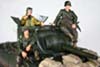
This is a very interesting vehicle from all possible angles. What i thought at first was a rogue mercenary unit on an "African trip", just look at the faces on these guys, this is really a US Army vehicle in Vietnam. Notice how the driver has extended the levers so that he can drive sitting on top of the vehicle, and he is also manning an M-60 machine gun. After market decal producers will hopefully create series of Vietnam era M113 markings like these in 1/16 scale, please.
continuing on following post
Yes, with maybe 1000 pictures of M-113 in action in Vietnam, this compendium by Jerzy Krzemiński is a fantastic source of information for M113 builds. I went through it twice. In addition to the regular US M113A1, it shows all variants and also vehicles from Australian, Korean and Vietnamese units in Vietnam.
As i am near finalizing the model, i have to decide on armament, and how the crews and infantry will be displayed on top, i selected a few pictures of specific and also general interest for everyone who may not have time to do the same.
A generic M-113 ACAV, with a flash suppressor on the Browning M2, with two M-60 machine guns at the rear behind shields. I found out that crews are not often wearing standard T-56 tank helmets, usually have regular infantry helmets or none at all, likely due to heat or when out of combat zones.
- 1/16 RC M-113A1 ACAV - Converting the Takom/Andy's HHQ kit to RC
- 0.png (1.37 MiB) Viewed 1216 times
Infantry always sitting on top, mainly because of fear of mines and also for all the same reasons why no one likes to be at the bottom of the boat. Wooded boxes of all types are often used as seats. Notice different position for the radio antenna, next to the driver's hatch, or sometimes in the middle point.
- 1/16 RC M-113A1 ACAV - Converting the Takom/Andy's HHQ kit to RC
- 0a.png (1.37 MiB) Viewed 1216 times
The use of a M2 Browning at the rear instead of one of the M60 seems to be common in certain unit as both of these M113 have them, and on different side. Note how one soldier is sitting on the driver's hatch.
- 1/16 RC M-113A1 ACAV - Converting the Takom/Andy's HHQ kit to RC
- 1.png (1.18 MiB) Viewed 1216 times
The use of Miniguns seems to have been more popular than i thought. Notice the raised mount for an M2 at the rear. Whoever served it was really exposed.
- 1/16 RC M-113A1 ACAV - Converting the Takom/Andy's HHQ kit to RC
- 2.png (1.49 MiB) Viewed 1216 times
Another minigun, outside of the ACAV turret, with its own mount and light shield.
- 1/16 RC M-113A1 ACAV - Converting the Takom/Andy's HHQ kit to RC
- 3.png (680.55 KiB) Viewed 1216 times
And another Minigun, and notice that the driver is equipped with an M2 Browning.
- 1/16 RC M-113A1 ACAV - Converting the Takom/Andy's HHQ kit to RC
- 4.png (727.28 KiB) Viewed 1216 times
Twin M-60 machine gun mount at the rear, and what seems to be an M-1919 on a stand attached to the glacis.
- 1/16 RC M-113A1 ACAV - Converting the Takom/Andy's HHQ kit to RC
- 5.png (550.49 KiB) Viewed 1216 times
Good looking twin M2 Browning mount with flash suppressors on the commander's cupola.
- 1/16 RC M-113A1 ACAV - Converting the Takom/Andy's HHQ kit to RC
- 6.png (530.72 KiB) Viewed 1216 times
106mm recoilless gun on the right. Also notice the M-60 on the commander's cupola ACAV turret, without shield.
- 1/16 RC M-113A1 ACAV - Converting the Takom/Andy's HHQ kit to RC
- 6a.png (758.06 KiB) Viewed 1216 times
This is a very interesting vehicle from all possible angles. What i thought at first was a rogue mercenary unit on an "African trip", just look at the faces on these guys, this is really a US Army vehicle in Vietnam. Notice how the driver has extended the levers so that he can drive sitting on top of the vehicle, and he is also manning an M-60 machine gun. After market decal producers will hopefully create series of Vietnam era M113 markings like these in 1/16 scale, please.
- 1/16 RC M-113A1 ACAV - Converting the Takom/Andy's HHQ kit to RC
- 7.png (784.11 KiB) Viewed 1216 times
continuing on following post
Last edited by lmcq11 on Fri Jan 31, 2025 3:32 pm, edited 3 times in total.
Re: 1/16 RC M-113A1 ACAV - Converting the Takom/Andy's HHQ kit to RC
The crew has made themselves more comfortable with what seems to be custom seating arrangements.
Beach party, with beach chairs and guitar.
But some units definitely looked more formal than others...
Notice an M1919 coax machine gun on the ACAV turret.
Good detail on that M2 Browning flash suppressor that seem to have been used in maybe 10 to 20 % of times.
Notice the sand bags spread over the floor, added protection against mines. It is also clearer on this picture that some vehicles retained an L shaped metal sheet in position when the side skirts were removed.
Extended trim vane at the front of the vehicle, used for extra stowage space.
Good study of the soldier's faces and lifestyle
ARVN M-113 ACAV with M1919 instead of M60s at the rear.
This is it, plenty of ideas for this and future M113 projects.
Louis
- 1/16 RC M-113A1 ACAV - Converting the Takom/Andy's HHQ kit to RC
- 7a.png (806.29 KiB) Viewed 1205 times
Beach party, with beach chairs and guitar.
- 1/16 RC M-113A1 ACAV - Converting the Takom/Andy's HHQ kit to RC
- 7b.png (1.55 MiB) Viewed 1205 times
But some units definitely looked more formal than others...
- 1/16 RC M-113A1 ACAV - Converting the Takom/Andy's HHQ kit to RC
- 8.png (624.11 KiB) Viewed 1205 times
Notice an M1919 coax machine gun on the ACAV turret.
- 1/16 RC M-113A1 ACAV - Converting the Takom/Andy's HHQ kit to RC
- 8b.png (855.05 KiB) Viewed 1205 times
Good detail on that M2 Browning flash suppressor that seem to have been used in maybe 10 to 20 % of times.
- 1/16 RC M-113A1 ACAV - Converting the Takom/Andy's HHQ kit to RC
- 9.png (1010.43 KiB) Viewed 1205 times
Notice the sand bags spread over the floor, added protection against mines. It is also clearer on this picture that some vehicles retained an L shaped metal sheet in position when the side skirts were removed.
- 1/16 RC M-113A1 ACAV - Converting the Takom/Andy's HHQ kit to RC
- 10.png (1.14 MiB) Viewed 1205 times
Extended trim vane at the front of the vehicle, used for extra stowage space.
- 1/16 RC M-113A1 ACAV - Converting the Takom/Andy's HHQ kit to RC
- 11.png (962.14 KiB) Viewed 1205 times
Good study of the soldier's faces and lifestyle
- 1/16 RC M-113A1 ACAV - Converting the Takom/Andy's HHQ kit to RC
- 12.png (1.4 MiB) Viewed 1205 times
- 1/16 RC M-113A1 ACAV - Converting the Takom/Andy's HHQ kit to RC
- 13.png (1.22 MiB) Viewed 1205 times
ARVN M-113 ACAV with M1919 instead of M60s at the rear.
- 1/16 RC M-113A1 ACAV - Converting the Takom/Andy's HHQ kit to RC
- 20.png (523.46 KiB) Viewed 1205 times
This is it, plenty of ideas for this and future M113 projects.
Louis
Last edited by lmcq11 on Tue Feb 04, 2025 4:13 am, edited 1 time in total.
Re: 1/16 RC M-113A1 ACAV - Converting the Takom/Andy's HHQ kit to RC
Hi everyone,
The following posts are for the M2 Browning and commander's cupola.
I would normally have discarded the more or less satisfactory Takom M2 and used a Tamiya M2 from the M26 Pershing, like i usually do, but i decided to use the Takom on this build and see if i could improve it. I comes with an optional barrel with flash suppressor that i decided to use.
For the Browning to have gun flash, i used a 1mm bit to drill through both ends of the barrel, meeting in the middle. I had to cut the barrel a bit on the inside section because it was too long for the normal drill bit to reach the middle point. Drilling through a barrel is tricky to do as the hole has to be perfectly centered. Any deviation and the barrel is wasted.
This is how the barrel flash suppressor should look like, attached to the muzzle.
I tried to improve the bolts by scribing the lines on both side but it did not make it better. I really wanted to see the spacing and separation between the barrel and the bolts as seen in reference pictures. In the end, i completely removed the molded on inside bolts, to be replaced by brass.
At first, i used Albion 0.3mm brass tube from their assortment kit on the flash suppressor. It looked good most of the time but maybe a bit too thin. Depending on the angle in which i looked at it, it somehow did not look right, sometimes ok, other times way too thin. I decided to redo it. Be aware that the bolts are really tiny and much patience was required.
Take note that i inserted a 1mm brass tube throughout the barrel with a 0.80mm fiber optic in it, later cut, positioned correctly and glued. It solidified and gave the barrel some more structure, and allowed me to make the barrel strait with some light manipulations as i could see the drilling did not help it keeping strait.
The flash suppressor was redone with 0.5mm brass rods.
Although designed for the Tamiya M2, the Aber improvement set can be adapted to the Takom M2, with some difficulty. It is cheaper than purchasing one of those super fragile 3D printed M2 replacement.
Both sights need improvement, it depends on your tolerance level.
The Takom barrel support is badly designed and looks real bad with those holes going sideways instead of towards the center. There are obvious molding limitation in attempting to create this part in one piece. Tamiya had a better solution by splitting it in two halves. As the M2 is sitting on top of the model, such error is highly visible. The superb Aber brass barrel support part can be adapted to replace it. If not, then a Tamiya M2 available from Axel's Modellbau (the V/W sprues) without any improvement would look better than the Takom M2.
I had to rebuild the connection between the Takom barrel and the receiver using 3 layers of brass tubing. There is the smaller 1mm containing the fiber optic that is connected to a 3mm yellow LED that was trimmed to bare bone with a nail file to fit inside the machine gun, which also had its interior trimmed. The outer brass tube is for the barrel that shows through the barrel support from the outside. The tube in the middle is just to bridge the two into a solid barrel. The LED was tested and everything was then soaked in superglue before closing the receiver halves.
Wires were soldered to the LED metal connectors and the they were bended towards the front. The connections are hidden under the machine gun mount.
I was curious how the Takom handles, trigger and rear sight would look like. I was not impressed. The trigger is too thick, the handles are positioned too high. There is a pin at the bottom that i don't know what it is. Everything lacks finesse. I decided to remove the rear detail and i used the Aber parts instead. The rest looks good.
continuing on following post
The following posts are for the M2 Browning and commander's cupola.
I would normally have discarded the more or less satisfactory Takom M2 and used a Tamiya M2 from the M26 Pershing, like i usually do, but i decided to use the Takom on this build and see if i could improve it. I comes with an optional barrel with flash suppressor that i decided to use.
For the Browning to have gun flash, i used a 1mm bit to drill through both ends of the barrel, meeting in the middle. I had to cut the barrel a bit on the inside section because it was too long for the normal drill bit to reach the middle point. Drilling through a barrel is tricky to do as the hole has to be perfectly centered. Any deviation and the barrel is wasted.
- 1/16 RC M-113A1 ACAV - Converting the Takom/Andy's HHQ kit to RC
- 1b.jpg (1.02 MiB) Viewed 1129 times
This is how the barrel flash suppressor should look like, attached to the muzzle.
- 1/16 RC M-113A1 ACAV - Converting the Takom/Andy's HHQ kit to RC
- 1f.png (430.87 KiB) Viewed 1129 times
I tried to improve the bolts by scribing the lines on both side but it did not make it better. I really wanted to see the spacing and separation between the barrel and the bolts as seen in reference pictures. In the end, i completely removed the molded on inside bolts, to be replaced by brass.
- 1/16 RC M-113A1 ACAV - Converting the Takom/Andy's HHQ kit to RC
- 2.jpg (232.56 KiB) Viewed 1129 times
At first, i used Albion 0.3mm brass tube from their assortment kit on the flash suppressor. It looked good most of the time but maybe a bit too thin. Depending on the angle in which i looked at it, it somehow did not look right, sometimes ok, other times way too thin. I decided to redo it. Be aware that the bolts are really tiny and much patience was required.
Take note that i inserted a 1mm brass tube throughout the barrel with a 0.80mm fiber optic in it, later cut, positioned correctly and glued. It solidified and gave the barrel some more structure, and allowed me to make the barrel strait with some light manipulations as i could see the drilling did not help it keeping strait.
- 1/16 RC M-113A1 ACAV - Converting the Takom/Andy's HHQ kit to RC
- 2a.jpg (831.35 KiB) Viewed 1129 times
The flash suppressor was redone with 0.5mm brass rods.
- 1/16 RC M-113A1 ACAV - Converting the Takom/Andy's HHQ kit to RC
- 3.jpg (572.01 KiB) Viewed 1129 times
Although designed for the Tamiya M2, the Aber improvement set can be adapted to the Takom M2, with some difficulty. It is cheaper than purchasing one of those super fragile 3D printed M2 replacement.
- 1/16 RC M-113A1 ACAV - Converting the Takom/Andy's HHQ kit to RC
- 4g.jpg (1.06 MiB) Viewed 1129 times
Both sights need improvement, it depends on your tolerance level.
- 1/16 RC M-113A1 ACAV - Converting the Takom/Andy's HHQ kit to RC
- 5a.jpg (1013.35 KiB) Viewed 1129 times
The Takom barrel support is badly designed and looks real bad with those holes going sideways instead of towards the center. There are obvious molding limitation in attempting to create this part in one piece. Tamiya had a better solution by splitting it in two halves. As the M2 is sitting on top of the model, such error is highly visible. The superb Aber brass barrel support part can be adapted to replace it. If not, then a Tamiya M2 available from Axel's Modellbau (the V/W sprues) without any improvement would look better than the Takom M2.
- 1/16 RC M-113A1 ACAV - Converting the Takom/Andy's HHQ kit to RC
- 5b.jpg (721.56 KiB) Viewed 1129 times
I had to rebuild the connection between the Takom barrel and the receiver using 3 layers of brass tubing. There is the smaller 1mm containing the fiber optic that is connected to a 3mm yellow LED that was trimmed to bare bone with a nail file to fit inside the machine gun, which also had its interior trimmed. The outer brass tube is for the barrel that shows through the barrel support from the outside. The tube in the middle is just to bridge the two into a solid barrel. The LED was tested and everything was then soaked in superglue before closing the receiver halves.
Wires were soldered to the LED metal connectors and the they were bended towards the front. The connections are hidden under the machine gun mount.
- 1/16 RC M-113A1 ACAV - Converting the Takom/Andy's HHQ kit to RC
- 6b.jpg (770.97 KiB) Viewed 1129 times
I was curious how the Takom handles, trigger and rear sight would look like. I was not impressed. The trigger is too thick, the handles are positioned too high. There is a pin at the bottom that i don't know what it is. Everything lacks finesse. I decided to remove the rear detail and i used the Aber parts instead. The rest looks good.
- 1/16 RC M-113A1 ACAV - Converting the Takom/Andy's HHQ kit to RC
- 7.jpg (320.25 KiB) Viewed 1129 times
continuing on following post
Last edited by lmcq11 on Sun Mar 09, 2025 1:23 pm, edited 12 times in total.
Re: 1/16 RC M-113A1 ACAV - Converting the Takom/Andy's HHQ kit to RC
The instructions for the cupola lack steps and sequence. So, it needs some study before starting gluing parts. The lock inside the hatch has a problem and was discarded at this time until i can figure out what is wrong with it or with my interpretation. If put on like the instruction says, the hatch does not close... The locking on the outside was made functional with M0.8 brass bolts and nuts. There should normally be a large bracket with a rubber absorber for the hatch at the rear of the cupula to stop and support the hatch when it is opened but there is no mention of it in the instructions. Maybe it interfered with the ACAV armor. It will make sense once the ACAV shields are in place. I'll see later.
A tiny hole was made for the LED wire to enter the cupula at the base of the mount, and then directed towards the engine compartment for connection into LED5 port for flash and sound.
Shield installed. It was a struggle and i had to cut the positioning pins to make it fit in place.
Overview of the M2 Browining without the ACAV side shields. The periscopes will be inserted later, painted in black during the painting phase with the lens masked.
Machine gun flash and sound are functioning well.
The model as it stands today.
Regards, Louis
- 1/16 RC M-113A1 ACAV - Converting the Takom/Andy's HHQ kit to RC
- 7a.jpg (1.02 MiB) Viewed 1129 times
- 1/16 RC M-113A1 ACAV - Converting the Takom/Andy's HHQ kit to RC
- 7b.jpg (872.41 KiB) Viewed 1129 times
A tiny hole was made for the LED wire to enter the cupula at the base of the mount, and then directed towards the engine compartment for connection into LED5 port for flash and sound.
- 1/16 RC M-113A1 ACAV - Converting the Takom/Andy's HHQ kit to RC
- 7c.jpg (1.55 MiB) Viewed 1129 times
Shield installed. It was a struggle and i had to cut the positioning pins to make it fit in place.
- 1/16 RC M-113A1 ACAV - Converting the Takom/Andy's HHQ kit to RC
- 11.jpg (875.09 KiB) Viewed 1129 times
Overview of the M2 Browining without the ACAV side shields. The periscopes will be inserted later, painted in black during the painting phase with the lens masked.
- 1/16 RC M-113A1 ACAV - Converting the Takom/Andy's HHQ kit to RC
- 17.jpg (1.66 MiB) Viewed 1129 times
- 1/16 RC M-113A1 ACAV - Converting the Takom/Andy's HHQ kit to RC
- 17a.jpg (1.55 MiB) Viewed 1129 times
- 1/16 RC M-113A1 ACAV - Converting the Takom/Andy's HHQ kit to RC
- 19.jpg (1.7 MiB) Viewed 1129 times
- 1/16 RC M-113A1 ACAV - Converting the Takom/Andy's HHQ kit to RC
- 19a.jpg (1.39 MiB) Viewed 1129 times
Machine gun flash and sound are functioning well.
- 1/16 RC M-113A1 ACAV - Converting the Takom/Andy's HHQ kit to RC
- 21.png (2.48 MiB) Viewed 1129 times
The model as it stands today.
- 1/16 RC M-113A1 ACAV - Converting the Takom/Andy's HHQ kit to RC
- 22.jpg (2.03 MiB) Viewed 1129 times
Regards, Louis
Re: 1/16 RC M-113A1 ACAV - Converting the Takom/Andy's HHQ kit to RC
Hi everyone,
It's time to decide what kind of M-113 configuration i want. i did a lot of photographic research to see what was common and uncommon.
Takom provides two parts for the belly armour that equipped some ACAV vehicles. The only area that is apparent from the front on pictures is the inclined small plate on the lower hull with the 4 bolts. Before putting these on, i wanted to check if belly armor was really used or not.
The Takom box cover shows an ACAV vehicle with belly armour and with the 3 buoyancy modules on the glacis. Again, i did not recall seeing many of those buoyancy blocks in the past when looking at Vietnam war pictures.
I browsed again through about 1000 war pictures of M-113 in action from the link earlier included in this report. Not all pictures show a frontal view or a clear view of the lower hull but i was able to make some non scientific conclusions from photographic evidences.
Conclusion: Most M-113 ACAV in Vietnam did not have belly armour or buoyancy modules. Maybe they were more common in specific units but overall, maybe not more than 10% of vehicles i saw had those. Most Acav vehicle had the armored commander turret and the two M60 shields at the rear, as shown below.
Another conclusion: When there is a belly armor installed (note the bar at the bottom of the front lower hull), the buoyancy modules are also always installed. This makes sense, the buoyancy modules would have been added to counteract the weight of the belly armor and they helped keeping the nose of the vehicle up when entering and crossing water. Same thing in reverse, I did not see a vehicle with buoyancy modules that did not have belly armor, at least with a clear view of the front lower hull, without mud or else.
A vehicle with both. Take note of the driver on top of the vehicle, driving with lever extensions to help survive possible mine blasts.
When i saw belly armor without buoyancy modules, it is usually because the modules have fallen off, partially or completely. Take note of the external driver's position, with seat and extended levers.
Some more examples of M-113 ACAV with belly armor and buoyancy modules, but these are somewhat rare in the compendium. Also rare is to see both commander and driver with T-56 helmets, sitting as if they were on a parade, as shown on the Takom box cover.
So, for the modeller who wants a M-113 ACAV in Vietnam, having the belly armor and the buoyancy module is a question of personal taste. For historical accuracy, someone would have to pick a specific vehicle. In my case, i will leave these off as i prefer the lines of the M-113 without them.
Regards, Louis
It's time to decide what kind of M-113 configuration i want. i did a lot of photographic research to see what was common and uncommon.
Takom provides two parts for the belly armour that equipped some ACAV vehicles. The only area that is apparent from the front on pictures is the inclined small plate on the lower hull with the 4 bolts. Before putting these on, i wanted to check if belly armor was really used or not.
- 1/16 RC M-113A1 ACAV - Converting the Takom/Andy's HHQ kit to RC
- 000.png (451.67 KiB) Viewed 1055 times
The Takom box cover shows an ACAV vehicle with belly armour and with the 3 buoyancy modules on the glacis. Again, i did not recall seeing many of those buoyancy blocks in the past when looking at Vietnam war pictures.
- 1/16 RC M-113A1 ACAV - Converting the Takom/Andy's HHQ kit to RC
- 00.png (369.55 KiB) Viewed 1055 times
I browsed again through about 1000 war pictures of M-113 in action from the link earlier included in this report. Not all pictures show a frontal view or a clear view of the lower hull but i was able to make some non scientific conclusions from photographic evidences.
Conclusion: Most M-113 ACAV in Vietnam did not have belly armour or buoyancy modules. Maybe they were more common in specific units but overall, maybe not more than 10% of vehicles i saw had those. Most Acav vehicle had the armored commander turret and the two M60 shields at the rear, as shown below.
- 1/16 RC M-113A1 ACAV - Converting the Takom/Andy's HHQ kit to RC
- 0.png (831.43 KiB) Viewed 1055 times
- 1/16 RC M-113A1 ACAV - Converting the Takom/Andy's HHQ kit to RC
- 0a.png (434.98 KiB) Viewed 1055 times
Another conclusion: When there is a belly armor installed (note the bar at the bottom of the front lower hull), the buoyancy modules are also always installed. This makes sense, the buoyancy modules would have been added to counteract the weight of the belly armor and they helped keeping the nose of the vehicle up when entering and crossing water. Same thing in reverse, I did not see a vehicle with buoyancy modules that did not have belly armor, at least with a clear view of the front lower hull, without mud or else.
- 1/16 RC M-113A1 ACAV - Converting the Takom/Andy's HHQ kit to RC
- 1.png (200.47 KiB) Viewed 1055 times
A vehicle with both. Take note of the driver on top of the vehicle, driving with lever extensions to help survive possible mine blasts.
- 1/16 RC M-113A1 ACAV - Converting the Takom/Andy's HHQ kit to RC
- 1a.png (179.96 KiB) Viewed 1055 times
When i saw belly armor without buoyancy modules, it is usually because the modules have fallen off, partially or completely. Take note of the external driver's position, with seat and extended levers.
- 1/16 RC M-113A1 ACAV - Converting the Takom/Andy's HHQ kit to RC
- 2.png (952.49 KiB) Viewed 1055 times
Some more examples of M-113 ACAV with belly armor and buoyancy modules, but these are somewhat rare in the compendium. Also rare is to see both commander and driver with T-56 helmets, sitting as if they were on a parade, as shown on the Takom box cover.
- 1/16 RC M-113A1 ACAV - Converting the Takom/Andy's HHQ kit to RC
- 3.png (330.04 KiB) Viewed 1055 times
- 1/16 RC M-113A1 ACAV - Converting the Takom/Andy's HHQ kit to RC
- 4.png (716.04 KiB) Viewed 1055 times
- 1/16 RC M-113A1 ACAV - Converting the Takom/Andy's HHQ kit to RC
- 5.png (489.12 KiB) Viewed 1055 times
So, for the modeller who wants a M-113 ACAV in Vietnam, having the belly armor and the buoyancy module is a question of personal taste. For historical accuracy, someone would have to pick a specific vehicle. In my case, i will leave these off as i prefer the lines of the M-113 without them.
Regards, Louis
Last edited by lmcq11 on Sun Mar 09, 2025 1:33 pm, edited 2 times in total.
Re: 1/16 RC M-113A1 ACAV - Converting the Takom/Andy's HHQ kit to RC
Hi everyone,
Continuing with the build, this is the trim vane.
The trim vane is a reinforced plywood board attached to the glacis and lowered with an hydraulic arm when entering water. The M-113 could only enter very calm water and used its tracks to advance. The trim vane helped keeping the nose up in the critical phase of entering the water and during the swim. It was otherwise often used in lowered mode to carry extra stowage as shown below, and was sometimes broken and removed. Take note of the condition of the M-113 Acav crew and soldiers, very different that what Takom is promoting on its boxart and also what Jason Studio is proposing for crew and soldiers for this vehicle. I'll be reviewing those soon. Also notice the Browning M2 interestingly facing the rear.
A post war picture of a US crew crossing calm water during some trial. We can see that the crew and soldiers in the back are very much anxious and ready to bail out at the first sign of problems.
The trim vane on a Canadian M-113, made of plywood board with thin metal overlay on top and bottom.
It's attached with a double hinge that allow the board to be completely lowered.
This is the Takom trim vane, designed to be glued to the glacis, which would permanently block the engine access hatch. Not ideal as i still want to be able to access the engine compartment for RC maintenance. Another alternative is to leave it removable with magnets (nowhere to put those) or just deposited where it could fall down while operating the vehicle, eventually getting lost. My solution is to make the hinges operable.
Bolt heads are molded on the hinges section attached to the board.
However, for some reasons, the hull attachment were not given any bolt heads... The designers must have forgotten. Technically, anyone building a static version of it should be adding bolt heads to these. However, since i want to make a trim vane that can be lowered, i do not mind the situation.
So, the solution is to rework all the hinge sections, remove any bolt heads, drill through them and use brass M0.8 x 6 bolts and nuts to make working hinges. These hinges are very small and fragile. I looked at using brass M0.6 bolts but from experience, these are too fragile and break when facing any resistance. I therefore used M0.8 as they look just about right.
Continuing on following post
Continuing with the build, this is the trim vane.
The trim vane is a reinforced plywood board attached to the glacis and lowered with an hydraulic arm when entering water. The M-113 could only enter very calm water and used its tracks to advance. The trim vane helped keeping the nose up in the critical phase of entering the water and during the swim. It was otherwise often used in lowered mode to carry extra stowage as shown below, and was sometimes broken and removed. Take note of the condition of the M-113 Acav crew and soldiers, very different that what Takom is promoting on its boxart and also what Jason Studio is proposing for crew and soldiers for this vehicle. I'll be reviewing those soon. Also notice the Browning M2 interestingly facing the rear.
- 1/16 RC M-113A1 ACAV - Converting the Takom/Andy's HHQ kit to RC
- 0.png (468.7 KiB) Viewed 991 times
A post war picture of a US crew crossing calm water during some trial. We can see that the crew and soldiers in the back are very much anxious and ready to bail out at the first sign of problems.
- 1/16 RC M-113A1 ACAV - Converting the Takom/Andy's HHQ kit to RC
- 1.png (740.58 KiB) Viewed 991 times
The trim vane on a Canadian M-113, made of plywood board with thin metal overlay on top and bottom.
- 1/16 RC M-113A1 ACAV - Converting the Takom/Andy's HHQ kit to RC
- 2.png (2.38 MiB) Viewed 991 times
It's attached with a double hinge that allow the board to be completely lowered.
- 1/16 RC M-113A1 ACAV - Converting the Takom/Andy's HHQ kit to RC
- 3.png (1.2 MiB) Viewed 991 times
This is the Takom trim vane, designed to be glued to the glacis, which would permanently block the engine access hatch. Not ideal as i still want to be able to access the engine compartment for RC maintenance. Another alternative is to leave it removable with magnets (nowhere to put those) or just deposited where it could fall down while operating the vehicle, eventually getting lost. My solution is to make the hinges operable.
- 1/16 RC M-113A1 ACAV - Converting the Takom/Andy's HHQ kit to RC
- 4.jpg (1.17 MiB) Viewed 991 times
Bolt heads are molded on the hinges section attached to the board.
- 1/16 RC M-113A1 ACAV - Converting the Takom/Andy's HHQ kit to RC
- 4a.jpg (410.71 KiB) Viewed 991 times
However, for some reasons, the hull attachment were not given any bolt heads... The designers must have forgotten. Technically, anyone building a static version of it should be adding bolt heads to these. However, since i want to make a trim vane that can be lowered, i do not mind the situation.
- 1/16 RC M-113A1 ACAV - Converting the Takom/Andy's HHQ kit to RC
- 4b.jpg (948.76 KiB) Viewed 991 times
So, the solution is to rework all the hinge sections, remove any bolt heads, drill through them and use brass M0.8 x 6 bolts and nuts to make working hinges. These hinges are very small and fragile. I looked at using brass M0.6 bolts but from experience, these are too fragile and break when facing any resistance. I therefore used M0.8 as they look just about right.
- 1/16 RC M-113A1 ACAV - Converting the Takom/Andy's HHQ kit to RC
- 5.jpg (274.14 KiB) Viewed 991 times
- 1/16 RC M-113A1 ACAV - Converting the Takom/Andy's HHQ kit to RC
- 6.jpg (893.86 KiB) Viewed 991 times
- 1/16 RC M-113A1 ACAV - Converting the Takom/Andy's HHQ kit to RC
- 7.jpg (688.03 KiB) Viewed 991 times
Continuing on following post
Last edited by lmcq11 on Tue Feb 04, 2025 4:31 am, edited 4 times in total.
Re: 1/16 RC M-113A1 ACAV - Converting the Takom/Andy's HHQ kit to RC
Installing the bolts and nuts is tricky because there is not much room to use the screwdrivers, so i had to slowly use plyers to screw them into position. The hinges are a lot more solid than i expected.
Overview of the operable trim vane. Still need to do some finetuning and polishing. I found there is not enough structure around the hydraulic arm itself to make it operable as well, but it could be done, maybe on a future build. At this time, i am just happy to be able to manually lower the trim vane so that i can assess the engine hatch. The added benefit was to provide bolt heads to the hull attachment. And it was fun to make such improvement and see the trim vane being functional.
Half way, the hinges are working well. Notice the ejection pin marks on the inner section of the trim vane that needed to be hidden. In order to close properly, i needed to remove bolt heads at the bottom of the inner face and also some plastic around the hinges because they were making resistance and preventing the trim vane from closing properly. I am guessing Takom never really expected it to be made operable but the underside is still well detailed, including the link with the hydraulic arm.
Then all the way down, the double hinges are functioning well, just like the real thing.
The tip of the hydraulic arm is going all the way into its position inside the hole on the right side of the board. It seemed to me that the trim vane might have to be a bit lower against the glacis but the arm is preventing it from going any further. I need to check this further.
This is the middle seat module for the crew compartment interior. Both are folding seats that can be displayed in up or down position, and there is a platform for the commander to stand on when he is in his cupola.
Continuing on following post
- 1/16 RC M-113A1 ACAV - Converting the Takom/Andy's HHQ kit to RC
- 8.jpg (619.52 KiB) Viewed 988 times
Overview of the operable trim vane. Still need to do some finetuning and polishing. I found there is not enough structure around the hydraulic arm itself to make it operable as well, but it could be done, maybe on a future build. At this time, i am just happy to be able to manually lower the trim vane so that i can assess the engine hatch. The added benefit was to provide bolt heads to the hull attachment. And it was fun to make such improvement and see the trim vane being functional.
- 1/16 RC M-113A1 ACAV - Converting the Takom/Andy's HHQ kit to RC
- 9.jpg (2.41 MiB) Viewed 988 times
- 1/16 RC M-113A1 ACAV - Converting the Takom/Andy's HHQ kit to RC
- 10.jpg (1.57 MiB) Viewed 988 times
- 1/16 RC M-113A1 ACAV - Converting the Takom/Andy's HHQ kit to RC
- 11.jpg (1.51 MiB) Viewed 988 times
- 1/16 RC M-113A1 ACAV - Converting the Takom/Andy's HHQ kit to RC
- 12.jpg (1.76 MiB) Viewed 988 times
Half way, the hinges are working well. Notice the ejection pin marks on the inner section of the trim vane that needed to be hidden. In order to close properly, i needed to remove bolt heads at the bottom of the inner face and also some plastic around the hinges because they were making resistance and preventing the trim vane from closing properly. I am guessing Takom never really expected it to be made operable but the underside is still well detailed, including the link with the hydraulic arm.
- 1/16 RC M-113A1 ACAV - Converting the Takom/Andy's HHQ kit to RC
- 13.jpg (1.8 MiB) Viewed 988 times
Then all the way down, the double hinges are functioning well, just like the real thing.
- 1/16 RC M-113A1 ACAV - Converting the Takom/Andy's HHQ kit to RC
- 14.jpg (2.26 MiB) Viewed 988 times
- 1/16 RC M-113A1 ACAV - Converting the Takom/Andy's HHQ kit to RC
- 15.jpg (2.17 MiB) Viewed 988 times
The tip of the hydraulic arm is going all the way into its position inside the hole on the right side of the board. It seemed to me that the trim vane might have to be a bit lower against the glacis but the arm is preventing it from going any further. I need to check this further.
- 1/16 RC M-113A1 ACAV - Converting the Takom/Andy's HHQ kit to RC
- 16.jpg (838.44 KiB) Viewed 988 times
This is the middle seat module for the crew compartment interior. Both are folding seats that can be displayed in up or down position, and there is a platform for the commander to stand on when he is in his cupola.
- 1/16 RC M-113A1 ACAV - Converting the Takom/Andy's HHQ kit to RC
- 17.jpg (1.26 MiB) Viewed 988 times
Continuing on following post
Last edited by lmcq11 on Tue Feb 04, 2025 4:38 am, edited 5 times in total.
Re: 1/16 RC M-113A1 ACAV - Converting the Takom/Andy's HHQ kit to RC
Middle seats and commander's platform are temporarily put in place for the picture. It will be glued to the floor plates after painting.
Tail lights were installed and not made functional. There is only the left tail light that would have a red light. The tail light is molded solid and it would be difficult to carve the oval section to insert a red Led just to illuminate that top section of the left side. I never got good reviews on previous attempts of putting LEDs inside US tail lights so i decided this time that i would just paint them and forget about LEDs.
Left side
Right side
This is it for now. Next step, the crew and infantry riders. The ACAV shields will be done after that.
Regards, Louis
- 1/16 RC M-113A1 ACAV - Converting the Takom/Andy's HHQ kit to RC
- 18.jpg (1.96 MiB) Viewed 985 times
Tail lights were installed and not made functional. There is only the left tail light that would have a red light. The tail light is molded solid and it would be difficult to carve the oval section to insert a red Led just to illuminate that top section of the left side. I never got good reviews on previous attempts of putting LEDs inside US tail lights so i decided this time that i would just paint them and forget about LEDs.
- 1/16 RC M-113A1 ACAV - Converting the Takom/Andy's HHQ kit to RC
- 19.jpg (2.09 MiB) Viewed 985 times
Left side
- 1/16 RC M-113A1 ACAV - Converting the Takom/Andy's HHQ kit to RC
- 20.jpg (1.25 MiB) Viewed 985 times
Right side
- 1/16 RC M-113A1 ACAV - Converting the Takom/Andy's HHQ kit to RC
- 21.jpg (1.02 MiB) Viewed 985 times
This is it for now. Next step, the crew and infantry riders. The ACAV shields will be done after that.
Regards, Louis
Re: 1/16 RC M-113A1 ACAV - Converting the Takom/Andy's HHQ kit to RC
Hi everyone,
The following posts are for the initial design of the crew and infantry riders.
The kit comes with a single commander figure. As this is an APC with interior details, it should have a driver and other riders in a RC moving diorama. My initial wish was for a Vietnam conscript gypsy war wagon, but there are few figures that can be used.
I purchased the Jason Studio JS16019 4 resin figures combo developed for the M113. Individually, these figures are sold at a high cost but also sold as a combo package of 4, they end up at $30 each, which is a good price for high quality resin figures.
The package is excessively of high quality, custom designed prints certainly at a cost passed on to the buyer, but it looks real good. Figures are bagged and the small white box contains 3D printed fine details.
The first thing that caught my attention is the subdued badge of the 1st Air Cav on the two infantry soldiers. This is a really bizarre choice. The two light infantry soldiers would be more at home riding a UH-1H Huey helicopter than on a M-113. Although the Air Cav did operate some M-113, it was certainly not their primary war horse. There are heavy armored units that would have been a much better choice for M-113 riders than soldiers of the Air Cav. These 2 infantrymen also do not have flak jackets.
Starting with the driver. The details are extremely good. The helmet has additional 3D printed details for the microphone set that will only be added at the end of the build as they would not last long until the painted figure is firmly on his seat. And i will have to be extremely careful every time i raise the roof.
It also come with a seat replacement with a more refine texture, and which is lower than the Takom.
Interestingly, for a figure specifically designed for the M-113, the driver certainly does not fall in place. It is a real struggle to try to make him sit on the seat. He's all over the place except where he should be.
I had to file the butt in order for him to stay in place at the angle that i needed him to be.
In order to be correctly in the driver's position, back against the seat and in the middle of the hatch, i had to make him sit like this.
The new seat
The driver is finally able to sit correctly.
continuing on following post
The following posts are for the initial design of the crew and infantry riders.
The kit comes with a single commander figure. As this is an APC with interior details, it should have a driver and other riders in a RC moving diorama. My initial wish was for a Vietnam conscript gypsy war wagon, but there are few figures that can be used.
I purchased the Jason Studio JS16019 4 resin figures combo developed for the M113. Individually, these figures are sold at a high cost but also sold as a combo package of 4, they end up at $30 each, which is a good price for high quality resin figures.
- 1/16 RC M-113A1 ACAV - Converting the Takom/Andy's HHQ kit to RC
- 1.jpg (2.15 MiB) Viewed 865 times
The package is excessively of high quality, custom designed prints certainly at a cost passed on to the buyer, but it looks real good. Figures are bagged and the small white box contains 3D printed fine details.
- 1/16 RC M-113A1 ACAV - Converting the Takom/Andy's HHQ kit to RC
- 2.jpg (2.07 MiB) Viewed 865 times
The first thing that caught my attention is the subdued badge of the 1st Air Cav on the two infantry soldiers. This is a really bizarre choice. The two light infantry soldiers would be more at home riding a UH-1H Huey helicopter than on a M-113. Although the Air Cav did operate some M-113, it was certainly not their primary war horse. There are heavy armored units that would have been a much better choice for M-113 riders than soldiers of the Air Cav. These 2 infantrymen also do not have flak jackets.
- 1/16 RC M-113A1 ACAV - Converting the Takom/Andy's HHQ kit to RC
- 3.jpg (1.43 MiB) Viewed 865 times
Starting with the driver. The details are extremely good. The helmet has additional 3D printed details for the microphone set that will only be added at the end of the build as they would not last long until the painted figure is firmly on his seat. And i will have to be extremely careful every time i raise the roof.
It also come with a seat replacement with a more refine texture, and which is lower than the Takom.
- 1/16 RC M-113A1 ACAV - Converting the Takom/Andy's HHQ kit to RC
- 4.jpg (1.99 MiB) Viewed 865 times
Interestingly, for a figure specifically designed for the M-113, the driver certainly does not fall in place. It is a real struggle to try to make him sit on the seat. He's all over the place except where he should be.
- 1/16 RC M-113A1 ACAV - Converting the Takom/Andy's HHQ kit to RC
- 5.jpg (1.79 MiB) Viewed 865 times
I had to file the butt in order for him to stay in place at the angle that i needed him to be.
- 1/16 RC M-113A1 ACAV - Converting the Takom/Andy's HHQ kit to RC
- 6.jpg (1.69 MiB) Viewed 865 times
In order to be correctly in the driver's position, back against the seat and in the middle of the hatch, i had to make him sit like this.
- 1/16 RC M-113A1 ACAV - Converting the Takom/Andy's HHQ kit to RC
- 7.jpg (1.56 MiB) Viewed 865 times
The new seat
- 1/16 RC M-113A1 ACAV - Converting the Takom/Andy's HHQ kit to RC
- 8.jpg (1.61 MiB) Viewed 865 times
The driver is finally able to sit correctly.
- 1/16 RC M-113A1 ACAV - Converting the Takom/Andy's HHQ kit to RC
- 9.jpg (1.53 MiB) Viewed 865 times
- 1/16 RC M-113A1 ACAV - Converting the Takom/Andy's HHQ kit to RC
- 10.jpg (1.17 MiB) Viewed 865 times
continuing on following post
Last edited by lmcq11 on Mon Feb 10, 2025 10:05 pm, edited 5 times in total.
