Thanks Barry but just "Louis the Builder" would do fine.
Continuing with the build. With the delivery of the Henntec Idler adjuster and the Mato Stug III gearboxes, I have concentrated on the running gear.
I got to give it to Guido, his HennTec idler adjusters are unbreakable. This is not ideal for scratch building because I need to take them apart and modify to adapt to the subject. This is a No14 Panther adjuster that I just cut in half in order to mount on the reduced size of the M113.
 Viewed 4268 times")
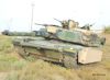
- M-113 M113 M-113A1 MRV 1/16 RC Scorpion Turret Australian Army build
This is the AFV-Model M113 Idler wheel, with its two (provided) ball bearings and a M4x12 metal pin available on eBay for a few pennies and used as an axle. It turns like a charm.
 Viewed 4268 times")
- M-113 M113 M-113A1 MRV 1/16 RC Scorpion Turret Australian Army build
I installed it like that, first with its central brass reinforcement but later removed as it is in the way of the interior floor. Its really not needed on a small M113.
 Viewed 4268 times")
- M-113 M113 M-113A1 MRV 1/16 RC Scorpion Turret Australian Army build
The hex bolt for the arm adjustment is accessible from a groove at the bottom.
 Viewed 4268 times")
- M-113 M113 M-113A1 MRV 1/16 RC Scorpion Turret Australian Army build
This is a Mato Stug III gearbox that I removed the drive axle. The fact that it is retained with gears can be easily unlocked from the main shaft by hex bolts is wonderful for scratch building. A new drive axle arrangement with the required length is designed and prepared from available material.
 Viewed 4268 times")
- M-113 M113 M-113A1 MRV 1/16 RC Scorpion Turret Australian Army build
A new shaft of 4mm in very thick brass is made to fit the AFV-Model sprocket. As the ball bearing on the Mato gearbox are 5mm, a thin aluminum 5mm spacer tube is used to bridge the gap and goes on top of the brass axle in the gearbox. And in similar fashion as the Mato axle, holes for the hex bolt are drilled to provide a good anchor for the gears on the axle. I had earlier purchased a true 4mm metal axle rod to use but I do not know what kind of material it is made of because it is so strong that I could not even create a scratch on it with my best metal blade. So, I had to go with plan B which is a very solid 4mm and thick brass tube, it should do well.
 Viewed 4268 times")
- M-113 M113 M-113A1 MRV 1/16 RC Scorpion Turret Australian Army build
The new shaft is mounted on the gearbox and tested for weaknesses.
 Viewed 4268 times")
- M-113 M113 M-113A1 MRV 1/16 RC Scorpion Turret Australian Army build
Change in plans. I earlier thought I could only do a partial interior with the Mato gearboxes, I mean without the driver's position. However, because I ordered 2 pairs of gearboxes from MatoMart in order to get the free shipping, I tried many options and I realised that if I use two right side gears, I could position them in a way to free the driver's area and get everything enclosed in the normal engine area of the M113. This is how the gearbox are installed. So now, this M113 MRV will have a full crew compartment interior.
 Viewed 4268 times")
- M-113 M113 M-113A1 MRV 1/16 RC Scorpion Turret Australian Army build
Notice the shaft extension for the right sprocket running through the front of the driver's position, in similar fashion as the real thing. An inner 5mm flanged ball bearing is keeping things aligned.
 Viewed 4268 times")
- M-113 M113 M-113A1 MRV 1/16 RC Scorpion Turret Australian Army build
The height and glacis angle of the M113 allows for unusual gearbox installations and mounting arrangement. After my third M113, I think I finally found the optimal gearbox and installation for those modellers wishing to build the interior.
 Viewed 4268 times")
- M-113 M113 M-113A1 MRV 1/16 RC Scorpion Turret Australian Army build
Continuing on following post