Hi,
On such build, the modeller like myself is left with his own resources to move forward, hoping for the best. Complaining will not get me anywhere, finding solutions do, while improving skills at the same time. The builder must have the right mind set to get into this stuff. I can see this is not for everyone.
This BMP-1 build is particularly interesting in the sense that every single assembly had a surprise and required some level of problem resolution.
Continuing with the hull
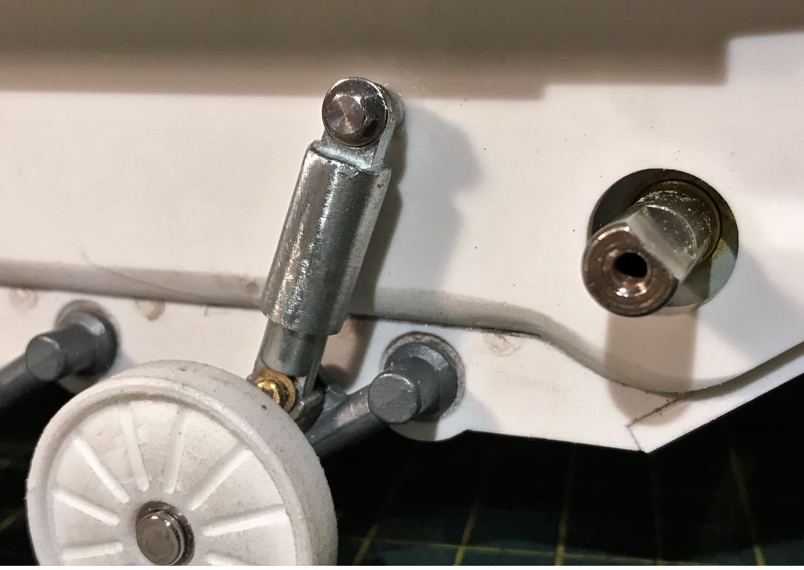
The PzIII shock absorber is refined and the spring is shortened. Updated version on the right.
 Viewed 6049 times")
- Ludwigs BMP1 BMP-1 IFV 1/16 RC build
With the front shock absorbers installed, I am no longer worried about the ability for the suspension to carry the weight of the gearbox and electronics at the front.
- Ludwigs BMP1 BMP-1 IFV 1/16 RC build
- Capture2.JPG (89.29 KiB) Viewed 6049 times
I had purchased a cheap Mato Tiger Idler adjuster from Mato Mart with the hope of using it for the BMP. However, after some study, I determined the design is not adaptable for modifications that would allow a good looking interior. I therefore have to select a more expensive HennTec Panther idler adjuster like I usually use. Its on order.
 Viewed 6049 times")
- Ludwigs BMP1 BMP-1 IFV 1/16 RC build
Starting the upper hull. The top needs to be made removable like any RC tank. To facilitate the assembly and placement of the upper hull parts on the lower hull, small drops of superglue are used to keep the parts in place where they connect with the lower hull. These temporary joints will be easily snapped once the structure of upper hull is fully built, strait and solid.

- Ludwigs BMP1 BMP-1 IFV 1/16 RC build
- Capture4.JPG (95.29 KiB) Viewed 6049 times
A PzIII gearbox is installed strait on the bottom beams, sockets for the screws were made with plasticard at specific locations, avoiding any contact with the torsion bars.
 Viewed 6049 times")
- Ludwigs BMP1 BMP-1 IFV 1/16 RC build
Some reinforcements are required during the assembly to ensure every part is strait.
 Viewed 6049 times")
- Ludwigs BMP1 BMP-1 IFV 1/16 RC build
The 3D printed top is partially sanded at first. Then I applied a layer of putty all over it which is then sanded in the hope of having a smooth surface. Honestly, I would have preferred a set of plasticard parts to assemble. It is not strait and needs a metal reinforcement strip under to make it flat.
 Viewed 6049 times")
- Ludwigs BMP1 BMP-1 IFV 1/16 RC build
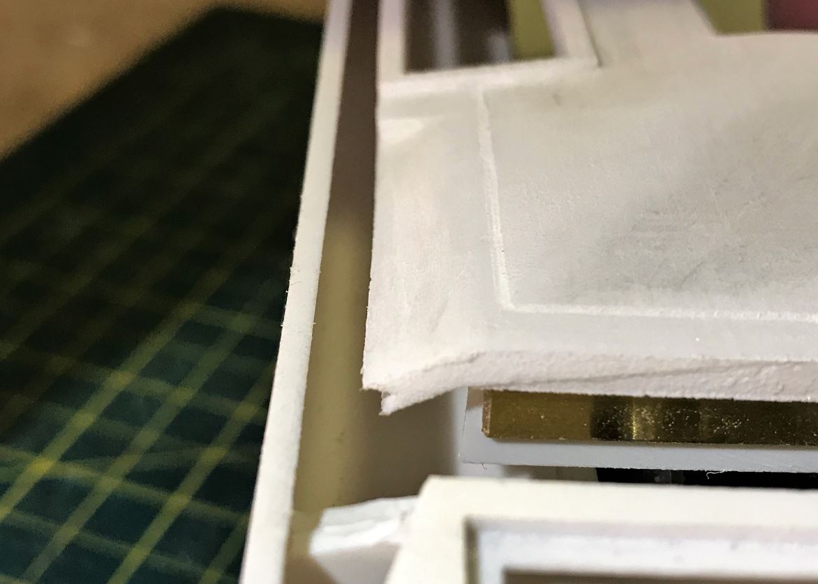
Bummer! the top is too narrow and it does not reach the hull sides... I re-checked that everything around was properly assembled. I see nothing wrong with the previous assembly and the angles of the side armor plates fit the Trumpeter kit. It looks like a design flaw. From the couple of pictures available on the Ludwigs website, I can see that the design of the lower hull has changed at one point because it is not like mine. Pictures show 2 variations. I can only guess what went wrong.
 Viewed 6049 times")
- Ludwigs BMP1 BMP-1 IFV 1/16 RC build
When one side is put on top of its base, the other side is missing 5mm to reach its base.
- Ludwigs BMP1 BMP-1 IFV 1/16 RC build
- Capture9.JPG (86.71 KiB) Viewed 6049 times
I do not want to change the angles of the side armor, therefore the top needs to be extended somehow. I installed a 5mm wide brass strip on both sides to create a bridge. With putty and some adjustment of the ventilation holes, it should be ok.
 Viewed 6049 times")
- Ludwigs BMP1 BMP-1 IFV 1/16 RC build
Continuing on following post