Hi,
Here is the M113A2 motorization, with 2 YouTube videos of the field trial at the end of this post.
First task was to create two 4mm chafts to connect the Traxxas drive chafts to the sprockets. They were made from M4 25mm long "stainless Lock Cotter Clevis Pins with flat Head Hole Cotter-Pins" bought on ebay from China for a few pennies. Original on top left.
 Viewed 10519 times")
- 4mm chafts
Then I created basic motor mounts in plasticard
 Viewed 10519 times")
- motor mount
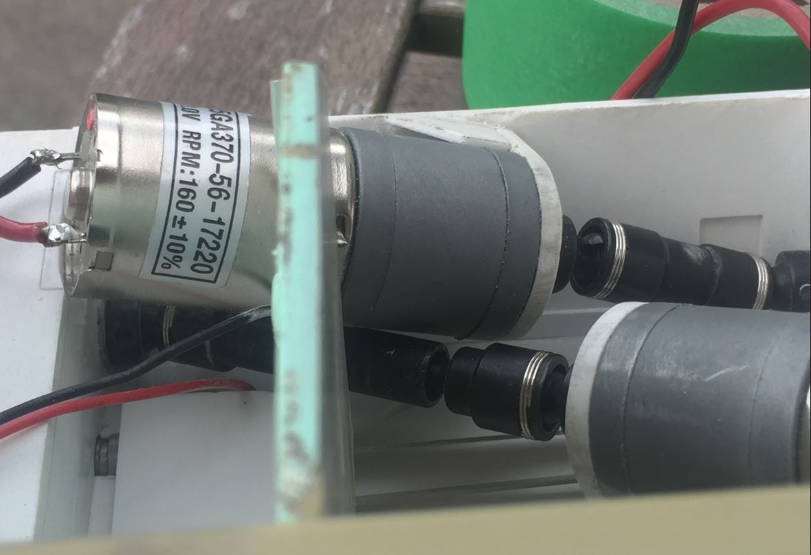
The mounting of the motors is quite unorthodox for an RC tank. Not sure you and I have ever seen something like this. Positioning trials were critical so that the drive shaft is placed with the least friction, then once the optimal position is found, the mounts are reinforced in place.
I wanted to free up as much space a possible in the driver's compartment. The arrangement mostly fit the allocated space for the engine and gearbox areas of the real M113. Use of Traxxas metal drive shafts provide a easy way to link the motors to the sprocket shaft. It runs quite smoothly. This motor arrangement is for a "crawler", so this model is not a "runner" like my M113A1 ACAV that was mounted with a Heng Long gearbox and Ludwigs Sprocket. This one is slow. The motors could take 12V if I wanted to.
 Viewed 10519 times")
- motor mounting
- motor mounting
- Capture5.JPG (83.5 KiB) Viewed 10519 times
Here are the M113 Sprockets and tracks bought from Tank Modellbau, minus the rubber pads that will be installed much later. You can see the M4 shaft on the sprocket, so forget about mounting these on a Heng Long gearbox. Every sharp edges on the sprocket teeth needed to be sanded smooth for proper operation. The tracks were easy to assemble once you develop a system to handle them. They links easily locks when the track is folded, which is annoying. Once installed through, they run smoothly.
 Viewed 10519 times")
- M113 Tracks and sprockets
 Viewed 10519 times")
- M113 Tracks and sprockets
The idlers are good but I noticed in the field trials that they do not freely roll despite the ball bearings, so I will need to look into it.
 Viewed 10519 times")
- M113 idler
I removed 1mm from the length of the Panther suspension arms so that the road wheels are better aligned with the sprockets and idlers. The Verlinden road wheels are performing well.
 Viewed 10519 times")
- M113 suspension and road wheels
The model as it stand today, with the Verlinden top and front temporarily in place on the bottom pic, just for the look. I have corrected the installation of the rear fuel cells, as per M113s seen in Calgary.
 Viewed 10519 times")
- Ludwigs / Verlinden M113A2
 Viewed 10519 times")
- Ludwigs / Verlinden M113A2
Here are 2 YouTube Videos of the motorization and running trials.
Motorization trials
https://youtu.be/APwVeTgIrpo
Running trials
https://youtu.be/JpoN0mcdx0E
Next step is to redo the rear ramp mechanism. The one I have created before my vacation had a failure, too much friction.
Regards, Louis