After finishing the return roller supports, I realized that I really needed to work on the interior of the lower hull. That would mean chopping out the battery box and the rear upright supports used to attach the lower and upper hulls. While I was doing this, it became very clear that the back hull was warped. So, the reinforcements would need to be glued down well to straighten it.
I chopped out the battery box and the other posts using a Dremel.
The idea is to have the inner reinforcement go a few millimeters above the lower hull and overlap with the upper hull. The idea is to block sand and grit from entering the hull. But, there will also need to be cutouts to allow for magnets holding the hulls together and wires from the head and convoy lights. The aft end will be a bit taller to support a shelf for switches and a charging port.
With interior cleared, I started working on the reinforcement in several stages. The first stage required creating templates using cardboard. This included test fitting the upper hull with the turret rotation motor. To get the switch shelf high enough, I have to work around the rotation motor. But this will allow access to the switches from the engine hatches. After the templates had been created, I cut the reinforcements from styrene using 3-mm styrene for the sides and 2-mm styrene for the rear. The rear also needed to have ½" holes cut for the exhaust. The holes need to be big so that they have room for the tubing to fit over the exhaust stubs. With the reinforcements cut, I test fitted them using rubber cement.
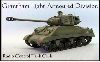
Then, I moved on to the front to work on reinforcing the front and installing the new gearboxes. The side reinforcements were also templated first using cardboard. I’m using 3-mm styrene to mount the gearboxes and raise them (sprocket needs to be raised by about 3-mm). I tried to template the mounting points by using cut nails in the screw holes. Sticking up, they could be pressed into the styrene sheet. Then, I drilled the holes and tried to line them up. It was close, but no cigar! The second attempt involved drilling the holes all the way through the hull. Then, I glued the sheet in place and drilled from the bottom of the hull into the styrene sheet.
Two notes on the gearboxes:
- To use the flat brass gearboxes, you’ll have to remove the two posts at the front used to secure the upper and lower hulls. Looks like another spot for magnets.
- The PzIV hull appears to be a few millimeters narrower than the PzIII hull. As a result, you can’t fit Speed400s into the PzIV on the flat, brass gearboxes.
The reinforcements in the rear have been epoxied in place using JB Weld. The shelf brackets are made from 5-mm triangle styrene and 3-mm styrene angle. I used plastic weld to make those permanent. The switch shelf is 2-mm styrene.
The front reinforcements are still only rubber-cemented in place. But, they took some checking and refitting to ensure that the return roller supports and the drive shaft bearings were installed well. Everything revolves around the gear boxes. So, once they are installed, test fit and install the bearings. Then, the return roller supports. From there I determined that I needed to create cutouts in the reinforcements for the bearings’ bolts and nuts. The 00-90 bolts had to be cut down and a cutout made in the reinforcement for the motor’s shaft. I’ll have to cut down the support roller shafts and make sure everything is right with test driving before gluing in the front reinforcements. So far, though, it looks good.
Note to self: next time, do all of the hull reinforcements before detailing the lower hull. Drill the guide holes and mark everything. But, don’t install it until after the reinforcements are done. That would have made it a lot easier to clamp everything down, especially in the back.
Pictures show:
Cardboard mock-ups:
Attempts to mark the styrene plate with nails: Looked good at first...
- IMG_0048 (2).jpg (75.23 KiB) Viewed 5191 times
Test fitting everything. Reinforcements and switch shelf supports are held in place with rubber cement. You can see how tight it will be to get the gearboxes and the motors in and out, particularly around the return roller supports.