Hi guys, thanks for the kind words! I must say I'm amazed I haven't had any pointy comments yet as I'm sure what I'm doing must be cray but meh maybe it's not as unlikely to succeed as I at first presumed

I've gone ahead with this method anyway and I now have some pictures of a full track to share! I won't be doing the other 3 for a while though as it's now time to finalise how to arrange the sprockets and bogeys and such, not to mention how to provide drive to a wheel in constant contact with the ground whilst still allowing it to be sprung... Thankfully I have a few thoughts on this which I'll be sharing shortly!
Before I get into pics, thanks ICE, I got into a nice rhythm with this method now but it still takes a lot longer to put them together than it does to cut the pieces to size! And blimp, I'd like to replace the twin pins with single 73mm ones (yep that's the final measurement of how wide these tracks are!) but that will require a staggering 26 meters of 1mm metal bar! I'm not convinced I can get that amount of metal cheaply anywhere so perhaps staggering them will be a cheaper alternative... You'll notice in these images I've actually pushed all the pins through to one side and it hasn't affected strength too much but I'd rather stick with either a central join or no join at all if I'm honest...
Anyway, now for the last pics of the day before I turn in and hope that my grill arrives tomorrow
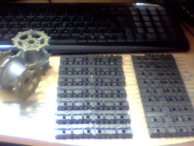
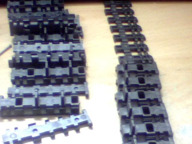
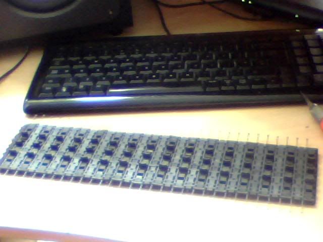
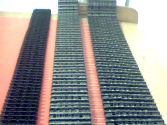
I didn't feel any need for WIP pics as the method of construction has already been explained (and what hasn't is a highly guarded secret aha!) so we'll get straight to the meat. From left to right here is a Tiger track at 43mm, a King Tiger track at 51mm and the newly forged
Mammoth track at 73mm!
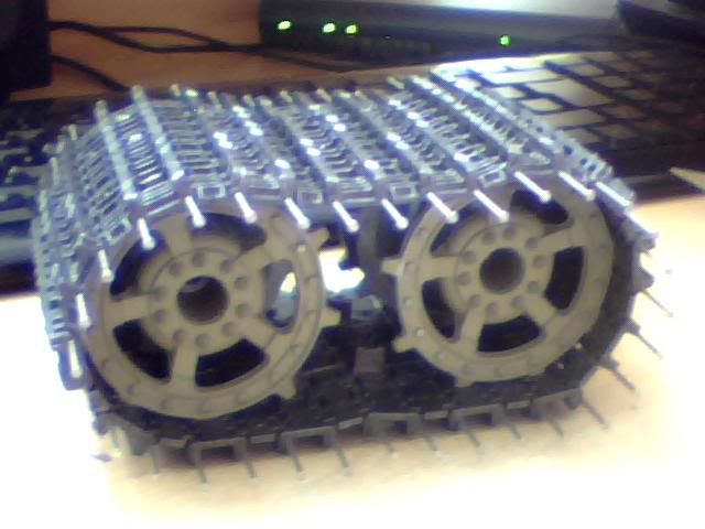
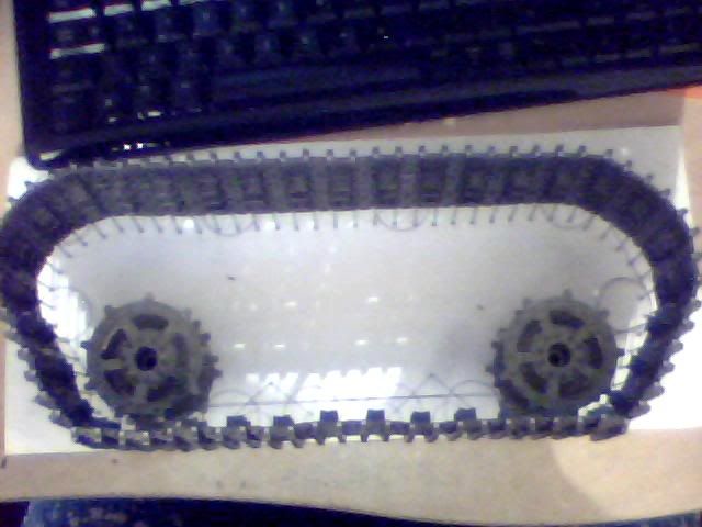
I tried to mock up a few images of the track how it will be used but these are all pretty crappy I'm afraid. Here is one of the general position it will take though. Sadly it's shorter than I expected so more links will need to be added in the future which will add to the already high number of 296 links! Looking on the bright side I've done 74 just today

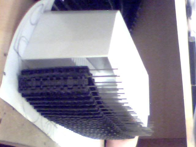
Here's a slightly better representative image to show the overall track width compared to the armoured carriage that will house it. There's about 8mm space either side of the track which amounts to 12.8cm in a real world scenario. More than enough I think but not too much as was the problem before.
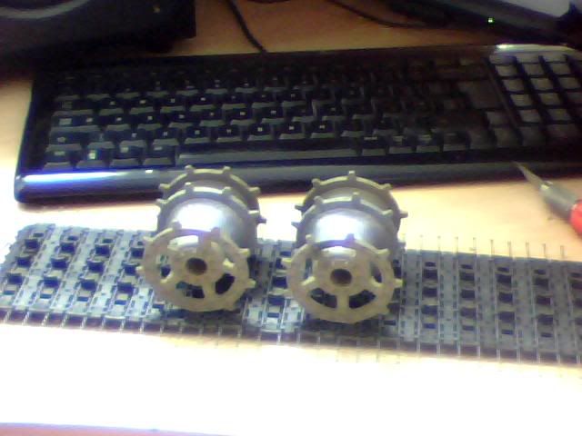
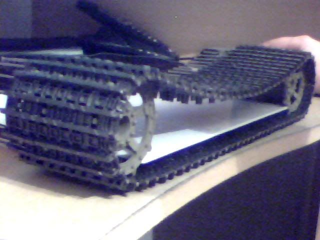
This was me playing with the sprockets but of course everything just wants to droop without any support at the top. I used a piece of the hull top (the engine cover!) to keep the sprockets apart for this shot. Looks good...
So one out of four tracks is done! Or at least it will be when I get round to adding a few more links but that can wait... Other good news is that the 16 sprockets I have will make me 8 double width drive wheels so that part of the build is now accounted for. I also have 4 gearboxes which will do nicely and 2 sound and 2 smoke units for later down the line if I decide to get fancy! I have other stuff too but I don't get how the controllers work so that can wait until the tank actually looks a bit more like a tank for now...
My next job, until the grill arrives at least, is to finally decide on the bogey, drive and suspension arrangements for each track. All four will be identical which saves work but I could use some advice on this from people who know what will work and what won't. I've been doodling this evening and think I have a good solution which for now I've thrown together as a quick paint image. Here it is, explanations follow...
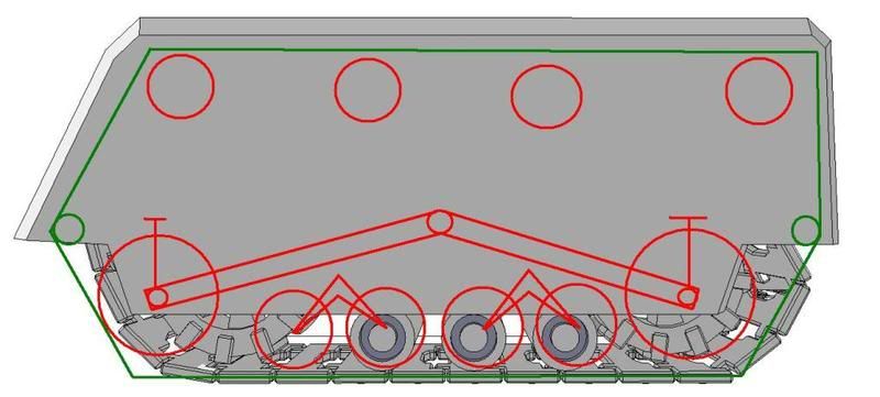
As I've said before, the Sketchup file I'm using is NOT my work and also is not entirely accurate but it makes a great background for this example... Obviously the green line is where I'd like the track to run and red circles are the sprockets and such. The largest ones in the botom left and right are my double width drive wheels as seen above, smaller ones are bogey wheels which will need to be scratchbuilt or modified from existing kits/models.
Due to the width of track I'm using, all the bogey wheels will be double width and 3 locating tangs (instead of the usual 2) will keep the track running along them centrally. The four wheels on the bottom ( I know there need to be four from original game artwork) would be best as two twin mountings in my opinion so that's what those wierd arrow things are meant to represent! Now I know what these are and how they work etc. but for the life of me I can't determine whether this kind of arrangement has a specific name. Please let me know if it does as it will help my googling and ebaying where necessary! The 4 wheels at the top will be the same double-bogeys (no golfing pun intended) as used in the bottom but they's be permanently fixed in position with a rod which will pass through both sides of the track carriage, allowing them to rotate freely but not to move in any direction.
Now the contraption emanating from the small circle in the centre of the image is (I think) of my own creation. I've certainly not seen it used before but it makes logical sense in my engineers mind so I'm going to put it out there for some feedback... I'm thinking that as I must place the drive wheels on the ground and as they must be driven and sprung, there are very few solutions. This is the one I've come up with though...
Each track has the final drive of it's controlling gearbox entering the carriage centrally. Instead of being attached to a sprocket as usual it will be attached to 2 gears which will drive small chains (think bicycles and such) This chain will run to a similar gear fastened to the rear of each drive wheel at both the front and rear of the track. It will be constantly tensioned as both the final drive gear and the gear on the drive wheel shall be attached to opposite ends of a long inflexible strip of material. The end of this material to which the drive wheel is attached will be free to move in an arc with the final drive as it's origin and this will allow upward movement of the sprocket whilst maintaining permanent drive of the belt. Downward movement will be prevented by the presence of the track, upward movement will be limited by a stopper and a suspension unit and this same unit will ensure the normal position for each wheel is at the same level as the four bogey wheels between the two drive wheels.
As you can see from the illustration there are also two green circles to the left and right which serve only to control the path of the track to something more pleasing and reflective of the size and shape of the carriage itself. I'm currently uncertain how to implement this as there will be little room in either of the areas indicated so bogey wheels are out of the question. I'm thinking that a sprung tensioner could be the answer but rather than have it mounted inside the track pushing out I could install it from the outer edge of the armour and have it pulling the track instead. I'll explain more and possibly share some more detailed illustrations tomorrow but for now I'm ready for a good night sleep!
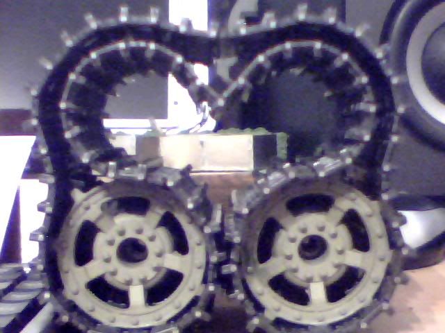
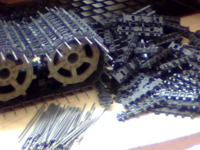
Any thoughts on the above please be sure to share them. Good or bad, I'd rather any flaws were revealed now than weeks from now when it's too late to avoid catastrophe! As a parting gift here's an image of the way I left the track before I sat down to write this update. Purely coincidental but I give you 'Love and War'!