- M3A3 Bradley US Cavalry Fighting Vehicle - RC 1/16 Build
- Capture11.JPG (174.41 KiB) Viewed 2045 times
- M3A3 Bradley US Cavalry Fighting Vehicle - RC 1/16 Build
- Capture11a.JPG (199.64 KiB) Viewed 2045 times
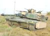
From this to that.
- M3A3 Bradley US Cavalry Fighting Vehicle - RC 1/16 Build
- Capture12.JPG (196.97 KiB) Viewed 2045 times
In parallel to the lower hull, the upper hull is calculated and transformations planned.
- M3A3 Bradley US Cavalry Fighting Vehicle - RC 1/16 Build
- Capture13.JPG (188.19 KiB) Viewed 2045 times
Molded on reinforcement braces at the back need to be removed with the Dremel, done outside in the wind and with an N95 mask.
- M3A3 Bradley US Cavalry Fighting Vehicle - RC 1/16 Build
- Capture14.JPG (215 KiB) Viewed 2045 times
I did four interior lights with LEDs, three for the main compartment and one that will go into the turret basket.
- M3A3 Bradley US Cavalry Fighting Vehicle - RC 1/16 Build
- Capture15.JPG (153.38 KiB) Viewed 2045 times
View of the upper hull interior, with bolted-on armor plates, turret rotation gear and its shield, and lights. The shield dimensions are calculated to fit the rim on the turret cage top.
- M3A3 Bradley US Cavalry Fighting Vehicle - RC 1/16 Build
- Capture16.JPG (148.85 KiB) Viewed 2045 times
First view of the interior core components. The turret cage is still loose at this time so that's why it is still showing some gaps. Later in the build, it will be firmly glued to the bottom of the hull. Notice how the upper lips of the cage fit below the turret rotation gear guard.
- M3A3 Bradley US Cavalry Fighting Vehicle - RC 1/16 Build
- Capture17.JPG (118.91 KiB) Viewed 2045 times
View with the lights on.
- M3A3 Bradley US Cavalry Fighting Vehicle - RC 1/16 Build
- Capture18a.JPG (134.84 KiB) Viewed 2045 times
Left side. Looks empty now but it will be filled with racks, shelves and equipment later. Temporary braces were added for the wiring.
- M3A3 Bradley US Cavalry Fighting Vehicle - RC 1/16 Build
- Capture19.JPG (118.5 KiB) Viewed 2045 times
Continuing on following post