BarryC wrote:Excellent engineering and detail work Louis!!
Thank you Barry. I've found the success factors of such project are mainly;
- 1/3 planning
- 1/3 decision making on the spot
- 1/3 luck
FredtheFrench wrote:10 years ago, I tought this tank was ugly, but since few years, I dream about a manufacturer for this tank at 1/16 scale at a good price, not DKLM at 1000$ with option...
Thank you, me too. Over the years, I got really bored of building Tigers and Panthers. These fringe design such as the Churchill suddenly becomes more interesting. Total costs will probably get close to an $800 figure when all is done. If i had known i would have made a Mk III, i would have asked Chris to sell me only the main chassis components. I am ending up trashing about half the basic kit.
This post is for the motorization, with a short video at the end.
The base kit comes with a two layer 3mm plastic base for the gearbox, inclined with a rest slot at the bottom for the bottom tip of the gearbox.
 Viewed 1212 times")
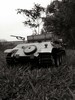
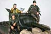
- RC 1/16 Churchill Mk III - Dieppe Raid 1942 - Build
The design is made to use these Mato Panther gearbox. The DKLM sprockets are made to fit the standard HL shaft.
 Viewed 1212 times")
- RC 1/16 Churchill Mk III - Dieppe Raid 1942 - Build
Installation of tracks and gearbox went pretty smoothly.
 Viewed 1212 times")
- RC 1/16 Churchill Mk III - Dieppe Raid 1942 - Build
The pre-drilled resting slot at the bottom were too far back. The sprocket was ending up about 5mm too much towards the reat. I had to use the Dremel to make a larger hole towards the front. New holes were made for M3 bolts into the base. The bolts are going strait into the plastic for a solid installation.
 Viewed 1212 times")
- RC 1/16 Churchill Mk III - Dieppe Raid 1942 - Build
 Viewed 1212 times")
- RC 1/16 Churchill Mk III - Dieppe Raid 1942 - Build
 Viewed 1212 times")
- RC 1/16 Churchill Mk III - Dieppe Raid 1942 - Build
The DKLM 3D printed sprocket seems to handle the metal tracks well. I am keeping the tracks very tight like the real thing. There is an armored plate that will cover it. I need to design a way to make that plate removable so that the sprocket remain easily removable.
 Viewed 1212 times")
- RC 1/16 Churchill Mk III - Dieppe Raid 1942 - Build
I did not realize the gearbox would be so much at the rear, with limited roadwheel support under it. The model is rear heavy. I will have to reinforce the suspension springs under the last 3 roadwheels.
 Viewed 1212 times")
- RC 1/16 Churchill Mk III - Dieppe Raid 1942 - Build
Here is a short video of the first motorization test with a TK-60.
It is running pretty smoothly. Once i reinforce the suspension under the gearbox, i will be doing a field test of the chassis. Then i will create some more details for the chassis.
Regards, Louis