Thank you SCHWEREPANZER and jhamm. I think it looks good but still far from perfect. That's my style.
Due to my RC and scale modelling addiction, my psychiatrist tells me that i should strictly aim for a 80% personal satisfaction rate on a build. First, i develop a vision as to how the model should look like, something exciting, and then i create small steps with specific objectives to get there. I like to work on a specific area for a couple of days, finish it to my liking before moving on to another area. Taking an area of a Ludwig basic kit that is about a 10% base and bringing it up to 80% within those 2 days is what i aim for. Getting the extra 20% would be difficult with the objectives, timelines and simple tools i use. Its very easy to make mistakes on such build. When i notice it, it is always an internal struggle whether i redo it, or live with it and move on. That's when the 80/20 rule comes handy.
Continuing with the build.
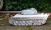
These are the rough Ludwig parts for the glacis coming with the kit. Designed for the Mk VII, it all need to be replaced for the Mk III.
 Viewed 918 times")
- RC 1/16 Churchill Mk III - Dieppe Raid 1942 - Build
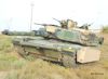
I completed a bit more of the AFV Club 1/35 kit so that i can use it as reference for hull shape and dimensions. The kit looks accurate so far, i did not see anything obviously wrong on the technical side. Eyeballing pictures and using questionable graphs would be more risky. Besides, not a single Churchill still in existence looks the same with field mods, incomplete or with restoration work.
 Viewed 918 times")
- RC 1/16 Churchill Mk III - Dieppe Raid 1942 - Build
A new glacis is made with some modifications to the angle and dimensions to fit the 1/35 kit extrapolated figures.
 Viewed 918 times")
- RC 1/16 Churchill Mk III - Dieppe Raid 1942 - Build
View of the frontal armor plate as seen on Prime Portal.
 Viewed 918 times")
- RC 1/16 Churchill Mk III - Dieppe Raid 1942 - Build
I took measurements from the 1/35 kit. According to my calculations, that frontal plate needs to be 5.5mm thick, with a visible separation between it and the main hull. With the base of the glacis done, i can go back to the idler extensions.
 Viewed 918 times")
- RC 1/16 Churchill Mk III - Dieppe Raid 1942 - Build
A piece of work that is critical for success on the idler adjusters is to correctly scribe the bolt thread inside the flat aluminum parts made of two halves. Done by slowly inserting an M2.5 bolt through them as few times.
 Viewed 918 times")
- RC 1/16 Churchill Mk III - Dieppe Raid 1942 - Build
The four idler extensions are complete with their working idler adjuster, minus the main bolt on order for 3 of them. The inner extensions were lengthened at the bottom to match dimension i recently noticed on the 1/35 kit, correcting an earlier mistake the best i can at this point.
 Viewed 918 times")
- RC 1/16 Churchill Mk III - Dieppe Raid 1942 - Build
The inner idler extensions are fully installed with their reinforcement braces seen in reference, while the exterior ones are simply held in place with a couple of drops of superglue for planning purposes. The idler wheels need to be installed on their axle before the exterior idler extensions are permanently glued in place. Once these are glued, there is no way back.
 Viewed 918 times")
- RC 1/16 Churchill Mk III - Dieppe Raid 1942 - Build
 Viewed 918 times")
- RC 1/16 Churchill Mk III - Dieppe Raid 1942 - Build
Building these idler extensions by constantly checking their position and alignment was critical. It looks promising. That's a load off.
 Viewed 918 times")
- RC 1/16 Churchill Mk III - Dieppe Raid 1942 - Build