Building a Mid-Production Normandy Tiger 1

This section is to 'show and tell' about any customizing or re-modeling you have done (or are doing) to a Heng Long tank.
Forum rules
This section is for posting a build log of your Heng Long tank.
Questions relating to issues you are having with your tank(s) should be posted in the General Questions forum here: viewforum.php?f=14
User avatar
tanks_for_the_memory
Sergeant
Posts: 501
Joined: Tue Jan 04, 2011 4:50 pm
Location: London

Re: Building a Mid-Production Normandy Tiger 1

Post by tanks_for_the_memory »

More work on the rear plate
Rear towing hitch on the Vimoutiers Tiger 1.jpg
Rear towing hitch on the Vimoutiers Tiger 1.jpg (32.73 KiB) Viewed 4098 times
Well gentlemen, I haven't been completely idle since my last post...

More model competitions for my boys - this time Euromilitaire 2015 in Folkestone. A fantastic show as always. This was the 30th anniversary and its sobering to realize that my last competition entry was at the very first one... 30 years ago I presume! I didn't win anything then - but fast forward three decades and my lads took five golds and a bronze between them! I will post some shots of their entries on my other blog in due course...

Anyway that's enough trumpet blowing for now. back to my own limitations...

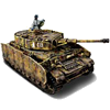
The rear plate still has plenty of frustrations in store, even after I 'conquered' the rear mud guards. And it still looks an unholy mess - can't wait to cover it all with my beloved zimmerit!

First up was the new rear towing bracket / pintle. Well I say it's for towing - I'm pretty sure I've seen some shots from Russia with Tigers towing spare fuel trailers from this. No doubt David will correct me here, but unlike some of the similar mounts on Panzer IVs, etc - which were part of the system for warming the engine using a blow torch - I don't think these had any other purpose. Instead, on the Tiger the blow torch was mounted on a detachable rhomboid plate shown above it in the shot below...
Rear towing hitch on the Saumur Tiger 1.jpg
Rear towing hitch on the Saumur Tiger 1.jpg (81.15 KiB) Viewed 4098 times
The rhomboid plate shown above it in this photo is part of the engine warming apparatus on the Tiger.

On the Heng Long Tiger there are just two stubs of plastic where the towing brackets should be. So I made mine by sanding two pieces of plastic card and drilling a hole of appropriate size. Note that the top piece is slightly thinner than that at the bottom.
The replacement rear towing pintle.jpg
The replacement rear towing pintle.jpg (32.37 KiB) Viewed 4098 times
It's not my finest hour - but it will do... especially when a little mud and weathering is applied.jpg
It's not my finest hour - but it will do... especially when a little mud and weathering is applied.jpg (31.85 KiB) Viewed 4098 times
My Mid-Production Normandy Tiger 1 build thread: http://www.rctankwarfare.co.uk/forums/v ... =22&t=8350
User avatar
jarndice
Colonel
Posts: 8023
Joined: Mon Sep 03, 2012 11:27 am
Location: the mountains of hertfordshire

Re: Building a Mid-Production Normandy Tiger 1

Post by jarndice »

TFTM, I am absolutely with you on matters concerning the TOWING BRACKET, easy to make but it really adds to the back plate especially when with the aid of a pin vise you put a towing pin with chain in place, :thumbup:
A word of warning, I have through my incompetence broken at least 2 towing brackets when reversing. :{
My heartfelt congratulations to your boys, I have good memories of the previous Dioramas they displayed and rightly were rewarded for their great work. :thumbup: :clap: :thumbup: :clap:
shaun
I think I am about to upset someone :haha:
User avatar
HERMAN BIX
Brigadier
Posts: 10323
Joined: Sun Jan 12, 2014 12:15 am
Location: Gold Coast,Australia

Re: Building a Mid-Production Normandy Tiger 1

Post by HERMAN BIX »

To right, your lads are shaping up to be right "Verlindens" mate ! you must be real proud.
Funny, the Tiger in Vimoutiers, when I saw it in 09 it appeared that someone had had half a go at removing it- souvenir I guess.
HL JAGDPANTHER,HL TIGER 1,HL PzIII MUNITIONSCHLEPPER, HL KT OCTOPUS,HL PANTHER ZU-FUSS,HL STuG III,HL T34/85 BEDSPRING,
HL PZIV MALTA,MATORRO JAGDTIGER,HL F05 TIGER,TAMIYA KT,HL PANTHERDOZER,HL EARLY PANTHER G,TAIGEN/RAMINATOR T34/76,
HL AN-BRI-RAM SU-85
User avatar
tanks_for_the_memory
Sergeant
Posts: 501
Joined: Tue Jan 04, 2011 4:50 pm
Location: London

Re: Building a Mid-Production Normandy Tiger 1

Post by tanks_for_the_memory »

Thanks for all the kind words - yes you bet I am proud. It's great to be able to pass on this hobby to the next generation.

Quite what will be going on in RC tanks and 1/16 scale in a few years' time - who knows.

Talking of which, whilst at Euromilitaire 2015 I did have a very interesting chat with a guy who was also at Tankfest with something VERY exciting:
Battletrax 1 10th scale RC Tiger 1.jpg
Battletrax 1 10th scale RC Tiger 1.jpg (92.78 KiB) Viewed 4075 times
This is a completely new 1/10 scale RC Tiger and there are other tanks planned...

See: http://www.battletrax.co.uk/index.php

I just had a look and it seems that no one has posted about this on this forum so far. I'm going to open up a new discussion about this right now. Please post there once you have had a look..

viewtopic.php?f=182&t=18089
My Mid-Production Normandy Tiger 1 build thread: http://www.rctankwarfare.co.uk/forums/v ... =22&t=8350
User avatar
tanks_for_the_memory
Sergeant
Posts: 501
Joined: Tue Jan 04, 2011 4:50 pm
Location: London

Re: Building a Mid-Production Normandy Tiger 1

Post by tanks_for_the_memory »

More work on the rear plate
Still a bit of a mess - but we're getting there. Voyager photo-etch exhaust shroud temporarily in place.jpg
Still a bit of a mess - but we're getting there. Voyager photo-etch exhaust shroud temporarily in place.jpg (40.02 KiB) Viewed 4052 times
I like working with plastic. It's what I've been used to for so many years. But there are times when you just have to accept that, balls-achingly tedious as it may be to work with, metal is just the right material...

I had planned to keep my original HL exhaust shields. They are quite nicely moulded and can be made to look quite thin with a bit of sanding down along the top lip. They can even be distressed with a little work with a blow torch and rotary tool. The bolt detail is quite simplistic so I decided to replace mine with much crisper resin ones from Masterclub. These can be bought in packs of fifty or so for a reasonable price so they should last for several projects (that's at least another decade for me then!)
The plastic exhaust shields suitably distressed....jpg
The plastic exhaust shields suitably distressed....jpg (37.91 KiB) Viewed 4052 times
Here is the type of bolt I used. Ironic that the Russians are improving a Tiger!.jpg
The Masterclub hex head bolts are tiny but beautifully moulded so they fit precisely into the hole drilled to the appropriate diameter.jpg
Close-up of the Masterclub hex-head bolts on the exhaust shield.jpg
Close-up of the Masterclub hex-head bolts on the exhaust shield.jpg (94.3 KiB) Viewed 4052 times
So was I happy with all my work? well, yes and no. The problem was that I had those lovely looking Voyager brass shields just sitting on my work bench. They come in the same set as the front and rear mudguards. Best of all they needed no soldering. Easy peasy right?

Wrong!
One half of the Voyager exhaust shields in their flat-packed state. I have already heated them over my gas hob and rubbed them with some fine grade sandpaper.jpg
One half of the Voyager exhaust shields in their flat-packed state. I have already heated them over my gas hob and rubbed them with some fine grade sandpaper.jpg (36 KiB) Viewed 4052 times
I found out the hard way that bending this brass into the correct curve is equally challenging as soldering the damn stuff. Then there is the small matter of working out how to attach them to the rear panel in a manner which is a) accurate and b) not likely to fall off the moment I breath on them.

That will be the subject of another post, but for now here's how one of them looked after I had finished with the bending bit:
Well at least it finally looks like a Tiger 1 exhaust shroud - but it wasn't easy!.jpg
Well at least it finally looks like a Tiger 1 exhaust shroud - but it wasn't easy!.jpg (33.72 KiB) Viewed 4052 times
My Mid-Production Normandy Tiger 1 build thread: http://www.rctankwarfare.co.uk/forums/v ... =22&t=8350
ALPHA
Major-General
Posts: 10963
Joined: Thu Oct 03, 2013 1:06 am

Re: Building a Mid-Production Normandy Tiger 1

Post by ALPHA »

Looks like you got it just right Tanks....it'll be ashamed when you dent it for effect ...though I think that would be another challenging task ;)

ALPHA
User avatar
tanks_for_the_memory
Sergeant
Posts: 501
Joined: Tue Jan 04, 2011 4:50 pm
Location: London

Re: Building a Mid-Production Normandy Tiger 1

Post by tanks_for_the_memory »

Thanks Alpha.

You want dents? You got dents!
Battle damage to the exhaust shields has commenced!.jpg
Battle damage to the exhaust shields has commenced!.jpg (35.95 KiB) Viewed 4050 times
And there's nothing subtle about it....jpg
And there's nothing subtle about it....jpg (34.1 KiB) Viewed 4050 times
My Mid-Production Normandy Tiger 1 build thread: http://www.rctankwarfare.co.uk/forums/v ... =22&t=8350
ALPHA
Major-General
Posts: 10963
Joined: Thu Oct 03, 2013 1:06 am

Re: Building a Mid-Production Normandy Tiger 1

Post by ALPHA »

:haha: :haha: That's not a dent...........that's a dink :haha: :haha:
Image
this one in your other photo is a dent lol....doing this type of dent might send you back to square one...Hate going back to square one ;)

Nice bullet holes though Tanks :thumbup:


ALPHA
User avatar
tanks_for_the_memory
Sergeant
Posts: 501
Joined: Tue Jan 04, 2011 4:50 pm
Location: London

Re: Building a Mid-Production Normandy Tiger 1

Post by tanks_for_the_memory »

OK, I accept the challenge Alpha - I will try to trash at least one of them...

First, however, I had to make them factory fresh.

Part of the difficulty in bending the exhaust shields to the correct shape is their profile - only the rear half is curved, while the front halves need to meet the rear plate at right angles. Obviously you also have to make them the correct width.

I had a look around my modelling area, then moved on to the kitchen, but try as I might I could not find a round object of the correct diameter. Eventually I hit on the idea of using two Valejo Air paint bottles masking taped bottom to bottom and these turned out to be just right. The fact that they were also slightly flexible also helped because I could squeeze the brass over them with my fingers.

As far as the width was concerned, this was simply a matter of trial and error - constantly test fitting them and then re-bending where necessary. Eventually I has what seemed to be the right shape...
The shape is a little complex because only the rear half is curved and the front halves have to meet the rear plate at a right angle.jpg
The shape is a little complex because only the rear half is curved and the front halves have to meet the rear plate at a right angle.jpg (36.97 KiB) Viewed 4037 times
Two Valejo Acrylic bottles taped bottom to bottom turned out to be the perfect template!.jpg
Two Valejo Acrylic bottles taped bottom to bottom turned out to be the perfect template!.jpg (38.59 KiB) Viewed 4037 times
The brass was then bent by hand over the bottles resting on a cork block.jpg
The brass was then bent by hand over the bottles resting on a cork block.jpg (34.04 KiB) Viewed 4037 times
So far all well and good. Next you have to work out how to attach them to the rear plate.

The originals were bolted to raised square lugs welded to the rear plate, not unlike those used for the side mudguards. Two of these can be seen in the photo of the towing hitch above. The Voyager set provides these as photo-etch to be folded oragami-style into the square blocks. This is unnecessarily over-complicated! Instead I simply made my square lugs from plastic card.
There are six attachment lugs for each shield.jpg
There are six attachment lugs for each shield.jpg (38.34 KiB) Viewed 4037 times
To help guide me I drew the outline of the shields on the rear plate.jpg
To help guide me I drew the outline of the shields on the rear plate.jpg (37.99 KiB) Viewed 4037 times
The next difficulty is getting them in the right place. You can look at photos of the real thing all you like, but if they don't fit your shields then this is not going to work. With more trial and error I managed to get them looking OK.
Here the shield is temporarily held in place using dress-making pins.jpg
Here the shield is temporarily held in place using dress-making pins.jpg (31.38 KiB) Viewed 4037 times
You can see here how the square lugs hold the shield away from the rear plate.jpg
You can see here how the square lugs hold the shield away from the rear plate.jpg (35.18 KiB) Viewed 4037 times
The pins come through the rear plate - once I have fixed the shields permanently in place these will cut short and glued for extra strength.jpg
The pins come through the rear plate - once I have fixed the shields permanently in place these will cut short and glued for extra strength.jpg (35.08 KiB) Viewed 4037 times
Last edited by tanks_for_the_memory on Sat Oct 17, 2015 12:33 am, edited 3 times in total.
My Mid-Production Normandy Tiger 1 build thread: http://www.rctankwarfare.co.uk/forums/v ... =22&t=8350
User avatar
tanks_for_the_memory
Sergeant
Posts: 501
Joined: Tue Jan 04, 2011 4:50 pm
Location: London

Re: Building a Mid-Production Normandy Tiger 1

Post by tanks_for_the_memory »

More work on the rear panel...

A simple way to strengthen the rear fender attachment point

I'm still nervous about how well all this photo-etch is actually going to stay on the tank - especially if I drive it around. The rear mudguards are a case in point. Although I have added extra support underneath they are held onto the rear of the Tiger just like the real thing - with three hinges. I'm hoping that bedding them in with a little zimmerit will help, but I came up with this idea to lend them a little helping hand.
A simple way to strengthen the fender attachments by adding some plastic to join the hinges.jpg
A simple way to strengthen the fender attachments by adding some plastic to join the hinges.jpg (39.85 KiB) Viewed 4006 times
The one on the left has already been trimmed to fit.jpg
The one on the left has already been trimmed to fit.jpg (35.56 KiB) Viewed 4006 times
This way each hinge supports the other and all attach to the rear panel at once....jpg
This way each hinge supports the other and all attach to the rear panel at once....jpg (38.78 KiB) Viewed 4006 times
A piece of plastic card was glued to the rear of the hinges only - thus allowing the mudguard to move as it is supposed to do. After this had dried I trimmed the rear to fit the profile of the hinges. As you will see, this means that the hinges are all attached to each other while at the same time giving a much larger area to attach them to the rear panel. It remains to be seen how well they stay in place!

I expect this extra plastic strip to be practically invisible once I put on the zimmerit. In fact there is an added bonus: as the zimmerit is always going to be a little more than true scale thickness this means that the fenders will sit slightly proud of the rear plate and thus look 'right'...
My Mid-Production Normandy Tiger 1 build thread: http://www.rctankwarfare.co.uk/forums/v ... =22&t=8350
Post Reply

Return to “Heng Long Builds”