
The first thing I would suspect is the PWM->PPM converter, as mentioned before. The TCB is designed for digital input and you'd really be doing yourself a favor to get a receiver that can spit out PPM, SBus, or iBus.
Nevertheless keep us posted, I'm enjoying your project.
Arduino 2560 project
Re: Arduino 2560 project
NO SUPPORT THROUGH PM - read why
-
wibblywobbly

- Major
- Posts: 6396
- Joined: Fri Oct 17, 2008 9:30 am
- Location: South Wales Valley
- Contact:
Re: Arduino 2560 project
Well after buying two new cheap 2560's, and having chatted to the understanding sellers who agreed to me returning them, I have discovered an important thing to bear in mind. The cheap boards have a CH340 chip on them, and this chip appears to be where communication problems occur.
As both of them told me, if I am going to use the board for something like the TCB firmware, then don't get a board with the CH340 clone chip.
They are easy to spot, the clone chip is a small rectangular chip. It sits just behind the USB socket.
The one to get is either a genuine board, or one that uses the same chip as the original. This is larger, square, and sits in the same place.
Fortunately, I found a company on Ebay that was selling off a stock of genuine, boxed Arduino's. They had bought them for a project and then decided to have their own board designed and produced. They were selling these off for 50% of the price of a genuine one.
Just in case the super cheap PWM>PPM converter I bought was what blew the old 2560 board (which may have been genuine, it has been sitting in a parts bin for years - it may have been playing up when it was used in a 3D printer?) I have a new converter on order, and will wait until I have that before plugging anything in.
Fingers crossed, and I will update when progress has been made.
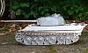
Tiger 1 Late
Panther G
King Tiger
M36 B1
Panther G
King Tiger
M36 B1
-
jhamm
- Warrant Officer 2nd Class
- Posts: 1068
- Joined: Fri May 19, 2017 7:21 am
- Location: Germany
- Contact:
Re: Arduino 2560 project
Hey Wibbly,
i use the 2560Core or 2560Pro Boards.
The reason is the 5V Power on the 2560Board deliver a current of maximum 1A.
This is not enough for a Reciever an two Servo and other 5V-Device.
Here an example with Mega2560Core Basic TCB without lights:
i use the 2560Core or 2560Pro Boards.
The reason is the 5V Power on the 2560Board deliver a current of maximum 1A.
This is not enough for a Reciever an two Servo and other 5V-Device.
Here an example with Mega2560Core Basic TCB without lights:
-
wibblywobbly
- Major
- Posts: 6396
- Joined: Fri Oct 17, 2008 9:30 am
- Location: South Wales Valley
- Contact:
Re: Arduino 2560 project
I am hoping to get away with 1 servo for the recoil, the turret motor and both drive motors will be powered from the battery via esc's, with just the signals going through the 2560. I could also use a UBEC to power the receiver.
It's early days, I enjoy tinkering with this sort of thing and seeing what works, and what doesn't.
It's always good to see how others use the system.
It's early days, I enjoy tinkering with this sort of thing and seeing what works, and what doesn't.
It's always good to see how others use the system.
Tiger 1 Late
Panther G
King Tiger
M36 B1
Panther G
King Tiger
M36 B1
-
wibblywobbly
- Major
- Posts: 6396
- Joined: Fri Oct 17, 2008 9:30 am
- Location: South Wales Valley
- Contact:
Re: Arduino 2560 project
Got it working. Did it the cheapest way possible.
Still need to sort out recoil, and muzzle flash.
The wiring looks a mess, this was a quick wiring job to test the circuits. It is being cut down to tidy it all up.
Cost once it is all done?
Arduino 2560 £10
3 x Bustaphedon 20amp esc's (drive and turret) £15
DasMikro Mini sound card (Benedini clone) £25
Speaker £10
PWM to PPM converter £10 (not needed if you have a PPM tx/rx)
Servo recoil £5
Tiger 1 Late
Panther G
King Tiger
M36 B1
Panther G
King Tiger
M36 B1
-
wibblywobbly
- Major
- Posts: 6396
- Joined: Fri Oct 17, 2008 9:30 am
- Location: South Wales Valley
- Contact:
Re: Arduino 2560 project
Now tweaked the settings, added a DasMikro Mini sound card, and it's running like a dream.
The wiring looks a mess as I just threw it in the hull to test it. I have all of the components on plugs, so in the event that any one component fails I can simply unplug it and replace it.
It's being nailed down and tidied up before I do the turret/recoil and muzzle flash.
The wiring looks a mess as I just threw it in the hull to test it. I have all of the components on plugs, so in the event that any one component fails I can simply unplug it and replace it.
It's being nailed down and tidied up before I do the turret/recoil and muzzle flash.
Tiger 1 Late
Panther G
King Tiger
M36 B1
Panther G
King Tiger
M36 B1
-
wibblywobbly
- Major
- Posts: 6396
- Joined: Fri Oct 17, 2008 9:30 am
- Location: South Wales Valley
- Contact:
Re: Arduino 2560 project
I have no idea whether anyone else has completed one of these projects.
I have the lower hull working like a dream, the sounds are excellent.
The turret is proving a challenge, so if anyone has got theirs working I would love to know how you did it.
All I need is:
A working servo recoil.
I have tried using 5v, Pin 25, and GND, directly to the servo. This wouldn't work in the real world as the Arduino can't supply enough power. It should work on a no-load servo, but it doesn't.
I have tried using a voltage regulator stepped down to 5.5v, with the signal wire going to pin 25, but that doesn't work either.
The only thing I haven't tried is running a GND from the battery negative terminal.
Snoop shows the stick as registering a cannon fire. But the servo doesn't activate.
Muzzle Flash.
Pin 41 is used for the HL high intensity muzzle flash. But hooking up a 5v led +GND simply gives a permanent 'on'. If memory serves me correctly the HL unit uses a capacitor. If the capacitor is charged on a permanent 5v supply it would explain why the led stays lit up.
I tried using the A8/A9 pins but the flash led will not light up. The Aux settings are defaulted to Output and Low.
I tried using the Auto Flash but no joy.
Auto Flash with Cannon
If this box is checked, the Aux Output will automatically be flashed (output brought high) whenever the cannon is fired, no function trigger needs to be created. If your muzzle flash is a simple LED, connect it to the Aux Output and check this option. But if you are using a Taigen High Intensity Flash unit, connect it to the dedicated Flash port on the TCB instead, in which case this Aux output can be used for other purposes.
However there is also this but I don't know if it applies to the DIY 2560 installation:Flash
The Aux Output can be set to flash (blink once). The length of time of the flash is specified on the Lights & IO tab of the OP Config program, from 1/1000th of a second to 5 seconds.
There are two ways to cause a flash to occur. You can check the “Auto Flash with Cannon” option in OP Config on the Lights & IO tab. Now any LED connected to the Aux Output will flash automatically when the cannon is fired. This will be the most common usage for those with LED muzzle lights. (But if you want to use a Taigen high-intensity flash unit the TCB has a dedicated port for that, see here.)
Or you can control the flash manually whenever you want, by assigning any trigger to the Aux Output - Flash function.
There is probably a very simple explanation for what I have missed, but if anyone has done it please post the solution up!Note that most of the eBay sellers will have the red and black wires opposite of what makes sense on the TCB. LEDs require a certain polarity so be sure you wire them correctly. For your convenience, positive and negative are printed on the bottom of the TCB board for every single output.
- Attachments
-
Tiger 1 Late
Panther G
King Tiger
M36 B1
Panther G
King Tiger
M36 B1
-
Rad_Schuhart
- Warrant Officer 1st Class
- Posts: 2089
- Joined: Tue Jan 19, 2016 9:22 am
- Location: Spanish living in Graz, Austria. Heart in UK.
- Contact:
Re: Arduino 2560 project
Great you have it working! If you can, a step by step tutorial would be great.
Next step for you would be to make your own open panzer sound board (Which is an unvaluable GEM). If you think the benedini sounds are excelent, you have yet to try the ones I did for the open panzer board
Next step for you would be to make your own open panzer sound board (Which is an unvaluable GEM). If you think the benedini sounds are excelent, you have yet to try the ones I did for the open panzer board
My RC tanks website, loads of free info for everybody:
https://radindustries.wordpress.com/
https://radindustries.wordpress.com/
-
wibblywobbly
- Major
- Posts: 6396
- Joined: Fri Oct 17, 2008 9:30 am
- Location: South Wales Valley
- Contact:
Re: Arduino 2560 project
It's just the turret that has me frustrated. The OpenPanzer Wiki deals with the stock TCB, but using an Arduino 2560 isn't covered all in one place.
A Russian guy, Sergey, has done it using a slightly different board, and his wiring is different, eg Pin 24 for the servo recoil rather than 25. He has used a voltage regulator to power the servo, but hasn't used the negative output, so I don't know if I should remove it as well. I am reticent to experiment in case I do some blue smoke magic.
I used the Tiger v3 sound file, the engine sounds are excellent, it sounds just like the Bovington Tiger, but the machine gun, and main gun volume is barely audible.
The low voltage detection doesn't function, I have a feeling that this is because a jumper is needed from Pin 15 to GND.
Once I know that everything works I will create a PDF with a full step by step guide. The lower hull is actually quite simple. I could have made it even tidier but wanted plugs on everything so that I can replace anything without resoldering.
It is running a PWM>PPM converter, which means that a standard tx can be used, which is what most people have.
Tiger 1 Late
Panther G
King Tiger
M36 B1
Panther G
King Tiger
M36 B1
-
Rad_Schuhart
- Warrant Officer 1st Class
- Posts: 2089
- Joined: Tue Jan 19, 2016 9:22 am
- Location: Spanish living in Graz, Austria. Heart in UK.
- Contact:
Re: Arduino 2560 project
Not sure about this anymore. Well, maybe among tamiya electronic tank users yes, but SBUS-IBUS is present everywhere now.wibblywobbly wrote:
It is running a PWM>PPM converter, which means that a standard tx can be used, which is what most people have.
In your case I already recommended you plugging an affordable multiprotocol module in the back of the radio, so you can use 16 channels and trigger all the functions the open panzer board lets you use. It also saves you the adaptor, and also the receiver is nail size, which is important in our tanks too. If in your writtings you can explain how to do it with SBUS, it would be very appreciated at least by myself.
Anyway I will read with A LOT of interest your PDF file, and I might try to do my own boards too. This is going to be a very interesting project!
My RC tanks website, loads of free info for everybody:
https://radindustries.wordpress.com/
https://radindustries.wordpress.com/
