 I have to admit I'm blown away by your progress and ideas. The view into the personnel compartment is fantastic!
M-113A1 ACAV APC - Vietnam - Build
-
c.rainford73

- Major
- Posts: 6104
- Joined: Thu Aug 25, 2016 7:34 pm
- Location: Connecticut USA
Re: M-113A1 ACAV APC - Vietnam - Build
Wow that's so absolutely cool LouisI have to admit I'm blown away by your progress and ideas. The view into the personnel compartment is fantastic!
I have to admit I'm blown away by your progress and ideas. The view into the personnel compartment is fantastic!Tanks alot.... 

Re: M-113A1 ACAV APC - Vietnam - Build
Hi,
Today, I got the ball bearings i ordered for the road wheels so i switched my attention from the rear ramp to them. I was anxious to see how the road wheels fit in.
I changed my earlier bad design and decided to use 3x8x4 mm F693zz Metal Flanged Ball Bearing Bearings as central piece to the fitting. These can be ordered on eBay from China. Got 10 of these for $9 (with free shipping) so this is a good deal, it just takes a while to arrive. They fit the Shapeways road wheels and my axles perfectly, a pleasant view.
The axles are Knupfer metal 3 X 20 pins, then cut to the proper length. Can get these for a few pennies each.
The Shapeways wheels are that, just wheels. The axles and fittings needs to be figured out. I made spacers out of 2mm plasticard to glue between the two wheels in order to get the proper spacing between them.
I have 20 shapeways road wheels worth $6 each for a total of $120 in expenses. Need to make 10 sets. The plasticard spacers were glued first to the interior of the inside wheel. Then i drilled the holes for the bolts from the outside and placed the bearings in the middle, making sure the rim of the bearing is flush with the spacer.
Then the outside wheel is glued to the spacer, making sure the holes for the bolts are aligned. The bolts are screwed all the way to the other side of the road wheels. These are Knupfer M1.2 X 8mm hex face brass bolts, worth a few euros for lots of 25. Need 100 of these in total. If you ever plan to do this, make sure to also order the special screwdriver made for these.
I cut the bolts on the other side so that they do not interfere with the roll. The axle pin is in place, very tight inside the bearings.
Road wheels are installed on the vehicle. Now, this is what i was really anxious to see. The space between the road wheel is very tight but they never touch. When i look at pictures of the real M113, the road wheels are also very tight together, so this seems ok... In any cases, i have no intentions of sanding the road wheels in an attempt to reduce the diameter.
Looking good i think... it worked. That is a releaf. On a project like this, major mistakes can happen anytime. But I like to do things i have not seen before. Its like pushing into the unknown. An Henntec adjuster was ordered for the idler. Hopefully, i ordered the right one...
When creating the road wheel fittings, it is important to measure everything in relations to the suspension arms so that the road wheels are perfectly aligned with the sprockets.
The centurion hub caps will be installed later. If the Shapeways road wheels had 8 bolts like it should have instead of 10, they would not look so crowded. The heads are a bit too big and it is normally the other end that should be present on the outside face, with a nut on each. However, i could not find 1.2mm nuts of the right size. With more knowledge and experience, someone can make a much better job i am sure.
Took me about 3 hours to make the road wheels, it was pleasant to design and to make these. The shapeways wheels are expensive but the rest was really cheap and it runs well for the type of use i will make. Ad Lav has a much better solution for heavy users.
Regards, Louis
Today, I got the ball bearings i ordered for the road wheels so i switched my attention from the rear ramp to them. I was anxious to see how the road wheels fit in.
I changed my earlier bad design and decided to use 3x8x4 mm F693zz Metal Flanged Ball Bearing Bearings as central piece to the fitting. These can be ordered on eBay from China. Got 10 of these for $9 (with free shipping) so this is a good deal, it just takes a while to arrive. They fit the Shapeways road wheels and my axles perfectly, a pleasant view.
- Flanged ball bearings
- Axle
- Spacers
- Shapeways M113 road wheel
- Shapeways M113 road wheel
- Shapeways M113 road wheel
- Shapeways M113 road wheel
- Shapeways M113 road wheel
- Shapeways M113 road wheel
- Shapeways M113 road wheel
Regards, Louis
-
c.rainford73
- Major
- Posts: 6104
- Joined: Thu Aug 25, 2016 7:34 pm
- Location: Connecticut USA
Re: M-113A1 ACAV APC - Vietnam - Build
Hi,
Here is the rear ramp.
These are the ramp parts coming with the kit. The frame on the upper left is for the hull. As for the frame on the lower left, the instructions show it being used on the inside of the door but i did not find a use for it.
Although the hatch is provided with a double layer for the right thickness, the kit does not provide it for the ramp itself and it must be created in plasticard, and must fit the thickness of the hatch.
The main ramp part provided shown here is too wide and must ne reduced by a few mm on each side in order to fit closer to the seal of the hull.
A lot of work is required to adjust, sand and finish the ramp with all its small detailed parts and moving components solidly in place.
The hatch can be opened and closed.
The kit part allows for a good representation of the inside of the hatch.
The hinges and door locking mechanism must be made functional.
The ability to lower the rear ramp is a critical aspect of the kit unless you are making it an amphibian and need to seal the whole thing. If made to travel on land only, i think it is important to capture an accurate look and feel of the ramp. It is fairly easy to achieve. The bottom hinges need adjustment for the proper fit, 3 X 8 brass bolts are used.
Small details will still be added to the door, including some tools and equipment on the outside. It will be done later in the finishing stage.
With the ramp in place, one of the next step is to design a system to open and close it using the elevation unit and a push rod.
Regards, Louis
Here is the rear ramp.
These are the ramp parts coming with the kit. The frame on the upper left is for the hull. As for the frame on the lower left, the instructions show it being used on the inside of the door but i did not find a use for it.
- Ludwigs M113 rear ramp
- Ludwigs M113 rear ramp
- Ludwigs M113 rear ramp
- Ludwigs M113 rear ramp
- Ludwigs M113 rear ramp
- Ludwigs M113 rear ramp
- Ludwigs M113 rear ramp
- Ludwigs M113 rear ramp
- Ludwigs M113 rear ramp
- Ludwigs M113 rear ramp
Regards, Louis
Re: M-113A1 ACAV APC - Vietnam - Build
Hi Louis,
This is a fantastic build, I have considered getting the M113 and you build is showing "the way".
Keep up the GREAT work!
Barry
This is a fantastic build,
Keep up the GREAT work!
Barry
"Details make perfection, and perfection is not a detail."
Leonardo Da Vinci
Leonardo Da Vinci

Re: M-113A1 ACAV APC - Vietnam - Build
Love it. Would look great next to my centurion or Freddys M48!
Re: M-113A1 ACAV APC - Vietnam - Build
Fantastic details. And so cleanly build. Just great
-
43rdRecceReg

- Major
- Posts: 6294
- Joined: Fri Jul 31, 2015 11:38 am
- Location: North West Highlands, Scotland
Re: M-113A1 ACAV APC - Vietnam - Build
Just followed your thread right through to this point, in one big sweep- with my admiration growing at every stage. Working on a basic Ludwig kit requires improvisation, as well as imaginative solutions- and here we find them in astonishing abundance. I bought some of his specialist parts (drive sprockets etc.) for my Cromwell project, but had to design and fabricate some parts. It was an invaluable experience; but seeing what you are achieving here, Louis, is adding to it immeasurably
"Get your facts first, and then you can distort them as much as you please"- Mark Twain.
-
Raminator

- Warrant Officer 2nd Class
- Posts: 1267
- Joined: Tue Aug 11, 2015 9:57 am
- Location: Newcastle, Australia
Re: M-113A1 ACAV APC - Vietnam - Build
I'm always impressed how you managed to fit all of the mechanicals into these open vehicles, Louis. The way you've squeezed those electronics into the front compartment is like plastic Tetris.
Re: M-113A1 ACAV APC - Vietnam - Build
Hi,
Thank you everyone for your kind words and encouragements.
I am finally back in town and can continue my model.
Below are the parts for the Henntec Panther track adjuster No15 that i had ordered and received this week. Major surgery is required to make it fit the M-113. Above are the Ludwigs 3D printed Idler wheels.
It was a struggle to figure out how to make it fit. Here is what is left of the main part.
Needed the whole arrangement to fit the allocated space under the fighting compartment floor. It must not show and nothing could stick out.
Had to make a small groove is order to allow for the adjuster pin to be reached.
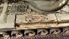
Here is a view of the Heng Long Panzer III tracks dry fitted, the adjuster is expensive but is a absolute must in order to have a good idler and also achieve the proper sag for the tracks.
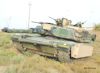
As an Vietnam theater M-113, the model will not be fitted with side skirts so the tracks are highly visible.
It was a struggle to find a way to link up the idler with the Henntec adjuster. Made an axle out of a 3mm pin and aluminum tubing.
Regards, Louis
Thank you everyone for your kind words and encouragements.
I am finally back in town and can continue my model.
Below are the parts for the Henntec Panther track adjuster No15 that i had ordered and received this week. Major surgery is required to make it fit the M-113. Above are the Ludwigs 3D printed Idler wheels.
- Henntec No 15
- Henntec No 15
- Henntec No 15
- Henntec No 15
- M-113 idler adjuster
- M-113 idler
- M-113 idler
