today you are going to correct one of the most important failures of the HL-Tiger.
What´s this failure about?
Well, let’s talk about some basics, here.
The turret of the Tiger is shaped like a round tin with a nose at the front.
Normally the center point of the turret is equal to the center point of the "tin".
The center point of the HL-turret is the center point of the whole turret.
That is 13mm to far to the front.
And that we have to correct.
Attention: If you correct this failure, the gun will not be able to shoot 6mm bullets anymore.
And again, you have two possibilities to solve the problem.
First and easiest one is to buy an adapter. The only one I know about is this one.
http://www.ludwigs-hobby-seite.de/Tiger1zubehoer.html
If you choose the hard and cheaper way, there are some steps to follow first.
1. Open and remove the Tiger tracks
http://www.rctankwarfare.co.uk/forums/v ... 18&t=11460
2. Open the Tiger
http://www.rctankwarfare.co.uk/forums/v ... 18&t=11461
3. Remove and open the turret
http://www.rctankwarfare.co.uk/forums/v ... 18&t=11467
Now let’s figure out the correct center of the turret.
Remember, the center point is the center of the "tin".
The turret diameter is about 145mm. So the radius is about 72,5mm.

The diameter of the inner ring is about 85mm.
So the radius is about 42,5mm.

That is a difference in radius about 30mm.
So the edge of the inner ring should be 30mm away from the edges of the turret. Everywhere.
It is ok to the sides but not to the back.
There it is 13mm to far away.


So we have to move the inner ring 13mm to the back.
And only to the back.
Let’s start.
First cut off the two support plates.
Remove them carefully.
You have to use them again.


Cut off the inner ring as shown.
Do it properly.

Then you position the ring as before and push it 13mm to the back.
Mark the new position.


Cut of the marked area.
Again properly.
Keep the piece for later.

Copy the cut off area to a 1mm poly plate.


Cut off the copied area.
Because you need to glue it to the lower turret part, leave a 3mm edge to do so.

Follow the next pictures.


Cut of two areas from the front.
The two support plates should fit there.
You´ll see later.
Glue the poly to the inside of the lower turret.

Glue both cut off turret pieces back to the poly as shown.

After the glue dried, glue the two support plates back to the old position.
If you don´t cut off these two areas, the plates will come up to high.
So the turret will not close properly.

Let’s move to the hull, now.
Here we also have to move the "big hole" 13mm to the back of the hull.

Because you need some edges to put glue on, you should use the next picture for details. "hinten" means back and "vorne" means front.

"Copy" the drawing to the hull.

To figure out the data I had to try a few times.
So don´t worry about those many lines.
Just copy the ones from the drawing.
Turn around the hull, remove the turning device and all the brackets.


Now cut off the marked area.

Just turning around the piece and gluing back together is not the right thing.
Because the ring is not equal in thickness you have to turn it down.
In the next picture you see, what I mean.
The top part is thicker then the bottom part.
That’s the front. In the back it is the other way round.
To keep it like it has to be, turn it down.
So the bottom will become the top.
I hope, I made it clear enough. (my English tststststs).


To glue the cut off area back to the hull, use small stripes of poly to create glue edges.
They should be 15mm in size.
Glue 10mm to the hull and leave 5mm for the area to glue.
Not more, because the glue edges of the cut off area are just 5mm wide

Then glue it back together.
Old position:

Turn down and new position:

To fill up the gaps and make them more stabile, I used 2-component-glue.
The advantage is you don´t even fill up the gaps, but gluing them together twice.
After drying, grind the gaps.
In the next picture I grind much more for some other details of my Tiger.
Don´t worry about that.
Just grind the glued gaps.

Fill up the back step of the lower turret part with body filler and grind it after drying.
This step was necessary, because the turret otherwise would touch some accessories when turning.
Now it is useless and even not original.

Now it is time to take care of the gun.
Dismount the gun
Disassemble the gun.
Follow the pictures.


Mount the gun back to the barrel.
Reassemble the turret.
The turret turning device needs a new position.
Take double-faced adhesive tape to fix it.
Of course you can choose different locations.
By the way, in the next picture you see a recoil unit from asiatam.
Not the one described above.
So don´t be confused.

Then reassemble the Tiger.
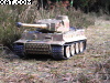
To show you the difference before and after, I took two Tigers for example.
Turret in 12 o´clock position shows no difference.

Turret in 9 o´clock position you can see the difference.
The lower one is the Tiger we worked on, upper one is an original HL.

If you take a look at the Tigers back, you can see, why the original needs that turret step.

Well, that´s it. Have fun by changing.
Greetings
Birger
For a lot more help with your Heng Long Tiger I tank, follow the below link ...
http://www.rctankwarfare.co.uk/forums/v ... 18&t=11459
