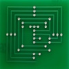
Electronics advice needed

Feel free to discuss anything and everything to do with tanking here!
Post Reply
User avatar
wibblywobbly
Major
Posts: 6396
Joined: Fri Oct 17, 2008 9:30 am
Location: South Wales Valley
Contact:

Electronics advice needed

Post by wibblywobbly »

I have built a custom IR sensor loom so that I can remote mount a battle system in my Panther. I am using an Elmod board, and Thomas kindly sent me this schematic showing how the Tamiya wiring is linked back to the Elmod 5 pin socket.
ElmodTamiya.JPG
ElmodTamiya.JPG (17.6 KiB) Viewed 2469 times
5. Status LED(+) VCC
4. Sensor Signal
3. Sensor GND.
2. Sensor Output
1. Status LED (-)

It does not have a seperate 2 pin IR emitter plug, it shares the 5 pin socket. I interpreted the schematic as follows, it is in the reverse order to the schematic just to complicate things, as looking at the board the schematic is reversed:

1. Status LED (-)
2. Sensor Output
3. Sensor GND.
4. Sensor Signal and IR(-)
5. Status LED(+) and IR(+) This is VCC eg constant 5v supply.

The IR emitter is connected to 4(-) & 5(+).
The status led's are connected to 1(-) & 5(+).
This should all have been fairly simple, but I am pulling my hair out.

What happens?
No IR emitter connected = The sensors do not detect shots.
IR emitter connected = Shots detected but IR stays lit on 2.3v. If I fire a shot the voltage increases to 2.9v.
Remove sensor = IR emitter behaves normally. No shot = 0v. Shot = 5v.

If I remove the signal leg of the sensor from the circuit and attach it to the (-) leg of the IR emitter, it completes the circuit and I get permament 2.3v, eg a dimly lit led.

So, there is a permanent 2.3v circuit going through the sensor to the signal leg, that is permanently lighting the emitter (I am using a standard visible 5v led so that I can see the led, rather than an IR led which would be invisible).

Thomas speaks good English, but not perfect, so before I go back to him, is there anyone out there who can tell me whether I have made a schoolboy error. I actually had it all working perfectly while I was constructing a prototype, but I have no idea what I did differently to make it work???

I can't find a Tamiya pinout anywhere, but if 3, 4 & 5 are the sensor, 1 & 2 are the status led's, and the IR is seperate, I really need to know which is which to get my circuit correct.

Any knowledgeble help would be much appreciated.

Cheers

RobG
Tiger 1 Late
Panther G
King Tiger
M36 B1
User avatar
wibblywobbly
Major
Posts: 6396
Joined: Fri Oct 17, 2008 9:30 am
Location: South Wales Valley
Contact:

Re: Electronics advice needed

Post by wibblywobbly »

It's ok, I cracked it. Pins 3,4 5 from a Tamiya circuit are the sensors, and I had the vcc power leg on the sensor in the wrong place. works like a charm now. In case anyone else buys an Elmod board I can confirm that if you want to save yourself the cost of buying an apple and the link cable, you can make one as follows:

With the board in front of you and the 5 pin socket on the left.

1. What are the pins in the socket?

Starting from the top:

1. LED (-)
2. Output leg of sensor.
3. GND. Connect GND leg of sensor.
4. Negative for IR emitter (-) =short leg of emitter.
5. Power supply. Connect (+) for 4 x status led's = long leg on each emitter, IR emitter = long leg of emitter, VCC leg of sensor.

You will need:
1 x YH70m IR emitter from Maplins.
4 x 5v led's, any colour you like.
4 x TSOP4878 IR sensors from http://cpc.farnell.com/vishay/tsop4838/ ... EML007-004
1 x 5 pin molex plug, the small one that Tamiya uses. A prewired one will save you a lot of work.
Narrow heatshrink for 'every' bare wire etc.

Plenty of fine cable 5 different colours is best.

The sensors can be daisy chained so a length of cable that goes from the plug to the first leg of a sensor, then another to the next first leg ...to the fourth.
Repeat this for the other two legs.
You then have all four sensors linked so that one pin on each is linked to the same one on the next sensor, with longer lengths running all the way back to the plug from the last sensor. You will have three wires Output, GND, Vcc.

The IR emitter is a simple two wire + & - task.

The status led's are all daisy chained like the sensors. All four have one pin linked, with the last leg having a longer strand running back to the plug. You will have two wires. + & -.

Solder it all up, make sure that the correct wires are connected as above, and admire your work.
Tiger 1 Late
Panther G
King Tiger
M36 B1
User avatar
wibblywobbly
Major
Posts: 6396
Joined: Fri Oct 17, 2008 9:30 am
Location: South Wales Valley
Contact:

Re: Electronics advice needed

Post by wibblywobbly »

And some pics
Attachments
Close up of sensors
Close up of sensors
How the sensors are linked.
Two wires that link to the IR emitter
Two wires that will link to the four status led's.
Using a block connector to test circuits, wires going in on left are in the same order as they left the plug.
IR socket
IR socket
Tiger 1 Late
Panther G
King Tiger
M36 B1
971wright
2nd Lieutenant
Posts: 2733
Joined: Tue Jul 22, 2008 8:16 pm
Location: nelson Lancashire

Re: Electronics advice needed

Post by 971wright »

Hi Rob nice to see you sorted it without frying anything :crazy: apart from a few brain cells lol


regards pete
edpanzer
Warrant Officer 2nd Class
Posts: 1317
Joined: Tue Jan 06, 2015 9:59 pm
Location: Peterborough Cambridgeshire UK

Re: Electronics advice needed

Post by edpanzer »

This fried my brain just reading it!!!!
Taigen Tiger 1 full option rctank.de special edition airbrush paint IR equipped
Type 90 1/24
WSN T34
Heng long leopard 2a6
Heng long panzer 4 platinum
Heng long sherman
Grantham Light Armoured Division RCTC
User avatar
wibblywobbly
Major
Posts: 6396
Joined: Fri Oct 17, 2008 9:30 am
Location: South Wales Valley
Contact:

Re: Electronics advice needed

Post by wibblywobbly »

It probably sounded more complex than it is, I was thinking about the circuitry as I was typing and going into detail, probably trying to solve my own problem on paper as I typed.

The daft thing is I sent a diagram of how I had set it up to Thomas, but he didn't spot that the sensor VCC leg was on the wrong pin. I was therefore chasing the wrong error and pulling my hair out in the process. I was quite concerned that I had blown something as nothing was making sense.

It's only 5 pins on the plug, 3 for the sensor, 2 for the status led's, and 2 for IR led. In theory the sensors can be damaged if the polarity is wrong, but mine seem to be ok, as they work off a tv remote in test mode.

I have printed a night sight that has been mounted next to the barrel, this holds the IR led, and ensures that where the barrel goes, so does the IR emitter. Just waiting for delivery of some yellow led's for the status lights, and I can re-assemble everything.

The same set-up can be used for Elmod's, Tamiya's, Clark's and IBU's, they all use the same 5 pin plug arrangement, but Elmod are the only ones who have dispensed with a separate IR emitter 2 pin plug, and instead ingeniously used the 5 pin plug to carry the signal. The components are as cheap as chips, when you think what Tamiya charge for an apple ..£80?, I doubt that this cost me £5 to build?
Tiger 1 Late
Panther G
King Tiger
M36 B1
User avatar
Tankbear
Lieutenant
Posts: 3001
Joined: Sun May 22, 2011 12:00 pm
Contact:

Re: Electronics advice needed

Post by Tankbear »

Hi rob

Agree the receivers are surprisingly simple. As you know a few years ago I did a little DIY kit with all the parts but very few people were interested. So I think most people are just afraid of dealing with electronics.

Guess tamiya know this and are happy to charge £80 for a few parts wrapped up in plastic.

Ian
www.mad-tanks.weebly.com
www.rctankelectronics.com
www.rc-truck.weebly.com
www.rc-boat.weebly.com
User avatar
wibblywobbly
Major
Posts: 6396
Joined: Fri Oct 17, 2008 9:30 am
Location: South Wales Valley
Contact:

Re: Electronics advice needed

Post by wibblywobbly »

Yup, I took one of those kits and installed it in my Bulldog, rejigged the loom to make it a nice neat fit, but the battle system is almost invisible. It's well worth doing.

(Note to attendees at the Yorkshire Show - lol - the Bulldog had pulled some solder joints apart, and as I discovered when I got home I had used a Panzer III track pin on one link, it was never going to end well... :P All working perfectly now.)

Comparing the same tanks which one looks better on a battlefield?
Attachments
DSCN1009[1].JPG
100_0766.jpg
100_0766.jpg (33.51 KiB) Viewed 2382 times
Tiger 1 Late
Panther G
King Tiger
M36 B1
Post Reply

Return to “General Discussion”